Table of Contents
Advertisement
Quick Links
Download this manual
See also:
Quick Reference Manual
Advertisement
Table of Contents
Troubleshooting

Related Manuals for Spectracom VersaSync


Summary of Contents for Spectracom VersaSync
- Page 1 ® VersaSync User Manual Document Part No.: 1228-5000-0050 Revision: 6.0 Date: 20-August-2018 spectracom.com...
- Page 3 Spectracom reserves the right to make changes to the product described in this document at any time and without notice. Any software that may be provided with the product described in this document is furnished under a license agreement or nondisclosure agreement.
- Page 4 Blank page. VersaSync User Manual...
-
Page 5: Table Of Contents
1.7 VersaSync Specifications 1.7.1 Supply Power 1.7.2 GNSS Receiver 1.7.3 Mechanical & Environmental Specifications 1.7.3.1 Physical Specifications 1.7.3.2 Environmental Requirements 1.8 The VersaSync Web UI 1.8.1 The Web UI HOME Screen 1.8.2 The INTERFACES Menu • TABLE OF CONTENTS VersaSync User Manual... - Page 6 2.6.1.2 I/O Signal Mapping Table 2.6.2 Configuring I/O Settings 2.6.2.1 How to Configure an Input Reference 2.6.2.2 How to Configure an Output 2.6.3 Example: Configuring a 20 PPS Output 2.6.4 Configurable I/Os 2.6.4.1 Configuring a 1PPS Input • TABLE OF CONTENTS VersaSync User Manual...
- Page 7 2.7.8.7 NTP Reference Configuration 2.7.8.8 NTP Servers and Peers 2.7.8.9 NTP Authentication 2.7.8.10 NTP Access Restrictions 2.7.8.11 NTP Expert Mode 2.7.8.12 Spectracom Technical Support for NTP 2.7.9 Configuring PTP 2.7.9.1 The PTP Screen 2.7.9.2 Enabling/Disabling PTP 2.7.9.3 Configuration — General Steps 2.7.10 GPSD Setup...
- Page 8 3.3.3.3 Selecting a GNSS Receiver Mode 3.3.3.4 Setting GNSS Receiver Dynamics 3.3.3.5 Performing a GNSS Receiver Survey 3.3.3.6 GNSS Receiver Offset 3.3.3.7 Resetting the GNSS Receiver 3.3.3.8 Deleting the GNSS Receiver Position 3.3.3.9 Manually Setting the GNSS Position • TABLE OF CONTENTS VersaSync User Manual...
- Page 9 4.4.1.4 Adding/Deleting/Changing User Accounts 4.4.2 Managing Passwords 4.4.2.1 Configuring Password Policies 4.4.2.2 The Administrator Password 4.4.2.3 Lost Password 4.4.3 Web UI Timeout 4.5 Miscellanous Typical Configuration Tasks 4.5.1 Creating a Login Banner 4.5.2 Show Clock • TABLE OF CONTENTS VersaSync User Manual...
- Page 10 5.1.1 Minor and Major Alarms 5.1.2 Troubleshooting: System Configuration 5.1.2.1 System Troubleshooting: Browser Support 5.1.3 Troubleshooting – Unable to Open Web UI 5.1.4 Troubleshooting via Web UI Status Page 5.1.5 Troubleshooting GNSS Reception • TABLE OF CONTENTS VIII VersaSync User Manual...
- Page 11 5.2.2 CLI Commands 5.3 Time Code Data Formats 5.3.1 NMEA GGA Message 5.3.2 NMEA RMC Message 5.3.3 NMEA ZDA Message 5.3.4 Spectracom Format 0 5.3.5 Spectracom Format 1 5.3.6 Spectracom Format 1S 5.3.7 Spectracom Format 2 5.3.8 Spectracom Format 3 5.3.9 Spectracom Format 4 5.3.10 Spectracom Format 7...
- Page 12 5.5 Product Registration 5.6 Technical Support 5.6.1 Regional Contact 5.7 Return Shipments 5.8 License Notices 5.8.1 NTPv4.2.6p5 5.8.2 OpenSSH 5.8.3 OpenSSL 5.9 List of Tables 5.10 List of Images 5.11 Document Revision History INDEX • TABLE OF CONTENTS VersaSync User Manual...
-
Page 13: Product Description
Product Description The Chapter presents an overview of the VersaSync Time and Fre- quency Synchronization System, its capabilities, main technical fea- tures and specifications. The following topics are included in this Chapter: 1.1 Getting Started 1.2 VersaSync Overview 1.3 Status LEDs 1.4 Interfaces Overview... -
Page 14: Getting Started
Welcome to the VersaSync User Manual . First steps: If you are not yet familiar with VersaSync, you may want to start here: "VersaSync Over- view" below. If you are ready to begin the installation process, see: "Initial Network Setup" on page 27... -
Page 15: Status Leds
I/O pins can be configured as TTL, 10 V pulse, RS232, RS422, and RS485. This allows VersaSync to provide a high number of outputs of the same type, while still fitting into a small form factor. However, if the combination of software configurable outputs is... -
Page 16: Blinking Intervals
"FAST" : blinking interval @ 8Hz "SLOW" : blinking interval @ 2Hz "HEARTBEAT" : sinus-shaped interval @ 1Hz 1.3.2 LED Lighting Patterns The table below indicates LED status light patterns for common VersaSync operating statuses. Table 1-1: Common light patterns Start-up HEARTB. -
Page 17: Legend, Individual Leds
Network OK, configuration OK Unit OK FAST Unit requires attention; check other status LEDs, see Web UI "LED Lighting Patterns" on the previous page HEARTBEAT See table Temperature OK FAST High temperature detected CHAPTER • VersaSync User Manual Rev. 6.0... -
Page 18: Led Patterns During Boot Sequence
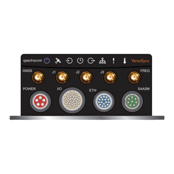
Navigate to MANAGEMENT > OTHER: LED Configuration , and set the Brightness level to "0". Interfaces Overview All of VersaSync's interfaces are integrated into the unit's connectors, which are located on the front panel: Figure 1-2: VersaSync front panel connectors CHAPTER •... -
Page 19: Input Timing Interfaces
1.4 Interfaces Overview Note: VersaSync is highly configurable and the connections can be adjusted many different ways. Your interface configuration may vary based on options you selected during the ordering process. The following interfaces are provided: 1.4.1 Input Timing Interfaces... -
Page 20: Connectors And Their Pinouts
1.5 Connectors and their Pinouts Connectors and their Pinouts All of VersaSync's connectors are provided at the front panel of the unit, below the Status LEDs. The Advanced Military Connectors are keyed for foolproof connectivity and offer a push-pull locking mechanism. - Page 21 485 signal +) 485 signal –) Have Quick input (RS- 485 signal –) (USB ded- icated) 1PPS output (10 V) Not connected ASCII output (RS-232) USB D– 1PPS input USB D+ ASCII input (RS-232) CHAPTER • VersaSync User Manual Rev. 6.0...
-
Page 22: Ethernet Connector
1.5.4 Optional I/O Connector The Optional I/O connector is used in conjunction with the Option Board that is available for VersaSync. If the unit is not equipped with an Option Board, this connector is not used. 1.5.5 Coaxial Connectors VersaSync offers five (5) coaxial connectors, three (3) of which can be configured at the fact- ory to accommodate requirements for e.g., IRIG AM signals or additional 10 MHz outputs. -
Page 23: Odu® Ordering Contact Information (Usa)
1.5 Connectors and their Pinouts Mating Connector Plugs The table below lists the part numbers for the mating connectors. The connectors can be ® ordered through Spectracom or ODU-USA Inc. All connectors are circular ODU AMC "mil- type" connectors. Table 1-8:... -
Page 24: Included Cables
1.6 Included Cables Included Cables The VersaSync Evaluation Kit contains the following cables (the antenna cable is not shown): Power Cable I/O Cable CHAPTER • VersaSync User Manual Rev. 6.0... - Page 25 1.6 Included Cables I/O Breakout Cable Ethernet Data Cable CHAPTER • VersaSync User Manual Rev. 6.0...
-
Page 26: Versasync Specifications
Satellites tracked : Up to 72 simultaneously Update rate : up to 2Hz (concurrent) Acquisition time : Typically < 27 seconds from cold start Antenna requirements : Active antenna module, +5V, powered by VersaSync, 16 dB gain min- imum Antenna connector : SMA CHAPTER •... -
Page 27: Mechanical & Environmental Specifications
Weight : 0.91 kg (2.0 lbs) 1.7.3.2 Environmental Requirements Temperature, in operation : -40°C to +65°C Temperature, in storage : -45°C to +85°C Humidity : 95% RH, non condensing at 40°C Altitude : up to 45,000 ft CHAPTER • VersaSync User Manual Rev. 6.0... -
Page 28: The Versasync Web Ui
Procedure 1 The VersaSync Web UI VersaSync has an integrated web user interface (referred to as "Web UI" throughout this doc- umentation) that can be accessed from a network-connected computer, using a standard web browser. The Web UI is used to configure and monitor the unit. -
Page 29: The Interfaces Menu
Spectracom Service. 1.8.2 The INTERFACES Menu The INTERFACES menu on the Main screen provides access to VersaSync's: External REFERENCES e.g., the GNSS reference input Detected OUTPUTS, such as 10 MHz and 1PPS Installed OPTIONS. -
Page 30: The Configuration Management Menu
1.8.3 The Configuration MANAGEMENT Menu The MANAGEMENT menu on the Web UI's Main screen provides access to VersaSync's con- figuration screens and settings. On the left side, under NETWORK , the following standard setup screens can be found:... -
Page 31: The Tools Menu
1.8 The VersaSync Web UI Time Management : Manage the Local Clock, UTC Offset, DST Definition and Leap Second information. System Time Message : Configure a regularly delivered message of the system time. Log Configuration : Manage the system logs. -
Page 32: Safety
Before you begin installing and configuring this product, carefully read the following important safety statements. Always ensure that you adhere to any and all applicable safety warnings, guidelines, or precautions during the installation, operation, and maintenance of your product. CHAPTER • VersaSync User Manual Rev. 6.0... -
Page 33: Safety: User Responsibilities
Do not modify the equipment. Use only spare parts authorized by Spectracom. Always follow the instructions set out in this User Manual , or in other Spectracom doc- umentation for this product. Observe generally applicable legal and other local mandatory regulations. -
Page 34: Safety: Other Tips
Apply technical common sense: If you suspect that it is unsafe to use the product, do the following: Disconnect the supply voltage from the unit. Clearly mark the equipment to prevent its further operation. CHAPTER • VersaSync User Manual Rev. 6.0... -
Page 35: Setup
The following topics are included in this Chapter: 2.1 Installation Overview 2.2 Initial Network Setup 2.3 Zero Configuration Setup 2.4 Accessing the Web UI 2.5 Setting up an IP Address 2.6 Configuring Inputs/Outputs 2.7 Configuring Network Settings CHAPTER • VersaSync User Manual... -
Page 36: Installation Overview
PC (CA08R- network. CRET-0002) : Connect the Multi I/O connector to the VersaSync unit. If you are using the Evaluation Kit, connect the Multi I/O USB output to a PC. Install a terminal emu- ®... -
Page 37: Mounting
UI (see "Zero Configuration Setup" on page 30). Using the Web UI, configure the following: Software-configurable I/O pins, see "Assigning I/O Pins" on page 36. Other VersaSync INTERFACES settings and MANAGEMENT settings e.g., network settings, reference priorities (see "Configuring Network Settings" on page 54). 2.1.2 Mounting 2.1.2.1... -
Page 38: Heat Dissipation
-40°C to +65°C. 2.1.2.3 Fasteners Spectracom recommends to observe the VITA 75 standard regarding mounting the unit, and fastener selection. CHAPTER • VersaSync User Manual Rev. 6.0... -
Page 39: Grounding
Default settings: VersaSync network settings default to DHCP: if the unit is connected to a DHCP server via ETH0 or ETH1, it will accept an assigned dynamic IP address. In order to apply a static IP address, DHCP must be disabled. (See "Assigning a Static IP Address"... -
Page 40: Network Address
Start the terminal emulator program on the PC. Select the COM port that is assigned to the USB interface: Access the CLI via ssh or telnet: The required port configuration is 115200 8N1: Press the Return key, and enter the login credentials: CHAPTER • VersaSync User Manual Rev. 6.0... - Page 41 IP address assigned to the unit. Take note of the IP address. You can use this IP address to login to the VersaSync Web UI and then set a static IP address, subnet mask and gateway. (This can also be done via the CLI and a terminal emulator.
-
Page 42: Zero Configuration Setup
2.3 Zero Configuration Setup Zero Configuration Setup As an alternative to the conventional network configuration, VersaSync can also be set up using the zero-configuration networking technology ("zeroconf"). Note: Zeroconf only works on DHCP-enabled networks. When using zeroconf, a TCP/IP network will be created automatically, i.e. without the need for manual configuration: Once VersaSync's ETH connector is connected to a hub, you can directly access the VersaSync Web UI, using a standard web browser, without any configuration. -
Page 43: Using Zeroconf
Using Zeroconf Connect to the Web UI of your VersaSync unit in these 3 steps: Connect VersaSync to a router on your LAN via the ETH connector (see "Initial Network Setup" on page 27). Connect the power supply to the VersaSync unit. -
Page 44: Setting Up An Ip Address
"Product Registration" on page 285. Setting up an IP Address In order for VersaSync to be accessible via your network, you need to assign an IP address to VersaSync, as well as a subnet mask and gateway, unless you are using an address assigned by a DHCP server. -
Page 45: Assigning A Static Ip Address
2.5 Setting up an IP Address 2.5.1 Assigning a Static IP Address There are two ways to setup a permanent static IP address, after connecting VersaSync to a DHCP network: Assigning a Static IP Address Using the CLI: Note: For your reference, the command... -
Page 46: Subnet Mask Values
"Configuring Network Settings" on page 54. 2.5.2 Subnet Mask Values Table 2-1: Subnet mask values Network Bits Equivalent Netmask Network Bits Equivalent Netmask 255.255.255.252 255.255.192.0 255.255.255.248 255.255.128.0 255.255.255.240 255.255.0.0 255.255.255.224 255.254.0.0 255.255.255.192 255.252.0.0 255.255.255.128 255.248.0.0 255.255.255.0 255.240.0.0 CHAPTER • VersaSync User Manual Rev. 6.0... -
Page 47: Configuring Inputs/Outputs
GNSS reference, see "The GNSS Reference" on page 147 in the Chapter MANAGING TIME. Note: The Network Ports eth0 eth1 can be configured under MANAGEMENT > Network Setup . For more information, see "Configuring Network Settings" on page 54. CHAPTER • VersaSync User Manual Rev. 6.0... -
Page 48: Assigning I/O Pins
2.6 Configuring Inputs/Outputs 2.6.1 Assigning I/O Pins VersaSync's I/O connector is software configurable, i.e. the pin interfaces and the signal mod- ulations can be configured by the user via the VersaSync Web UI. The software-configurable 26-pin I/O connector comprises 9 user-configurable Channels, plus one fixed USB interface. -
Page 49: Signal Types
Up to six TTL (5V) or 10 V DCLS outputs and three DCLS inputs are available for e.g., 1PPS, xPPS, IRIG B 00x, HaveQuick, ASCII ToD signal transmission. Single-ended Serial Lines VersaSync provides up to 3 RX and 3 TX RS232 interfaces for e.g., ASCII ToD – NMEA 0183 (ICD-GPS-153). Differential Serial Lines Up to four differential serial lines are available. - Page 50 ATC = ASCII Time Code Configuring a new Input or Output In the VersaSync Web UI, navigate to MANAGEMENT > NETWORK: Pin Layout . The Pin Layout screen will be displayed. Prior to assigning the new output, identify a pin pair in the pin Layout table that is not used (Signal = "None") or not needed.
- Page 51 In the Actions panel, click Apply Changes . Restoring the Default I/O Configuration VersaSync is shipped with a default I/O configuration that you can be customized. However, if required you can restore the default configuration at any time after applying changes.
-
Page 52: Configuring I/O Settings
(e.g., "GNSS reference"). In the Status window, click the GEAR button next to the desired input reference. The settings window for the chosen reference will be displayed. Edit the field(s) as desired. CHAPTER • VersaSync User Manual Rev. 6.0... -
Page 53: How To Configure An Output
The instructions below explain how to configure a 20 PPS output signal: First, assign a GPIO output to an I/O pin pair: In the Web UI, navigate to MANAGEMENT > NETWORK: Pin Layout . The Pin Layout screen will be displayed. CHAPTER • VersaSync User Manual Rev. 6.0... - Page 54 Under General , set the Output Mode to Square Wave , and check Output Enabled . To configure e.g., a 20 PPS signal, set the Pulse Width to 1 000 000 ns, and the Period to 50 000 000 ns: CHAPTER • VersaSync User Manual Rev. 6.0...
-
Page 55: Configurable I/Os
To configure a 1PPS Input: Navigate to INTERFACES > REFERENCES: PPS Input 0 (or: INTERFACES > OPTION CARDS: PPS Input 0 ). The PPS Input 0 Status window displays. Click Edit to open the configuration window: CHAPTER • VersaSync User Manual Rev. 6.0... -
Page 56: Configuring A 1Pps Output
Rising Falling Pulse Width [ns]: Configures the Pulse Width of the 1PPS output. [range = 20 to 900000000 ns = 0.0 μs to 0.9 s] [default = 200 ms] Click Submit. CHAPTER • VersaSync User Manual Rev. 6.0... -
Page 57: Configuring An Ascii Input
Format : Once a Format Group has been selected, one or more Format fields may appear, allowing you to select one or more time code Formats . For detailed spe- cifications and limitations on the supported time code formats, see "Time Code Data Formats" on page 246. CHAPTER • VersaSync User Manual Rev. 6.0... - Page 58 Auto is chosen as the format group, the format will auto- matically be Auto- detect. VersaSync will attempt to identify the format of the incoming ASCII message. Offset : Provides the ability to account for ASCII input cable delays or other laten- cies in the ASCII input.
-
Page 59: Configuring An Ascii Output
Configuring an ASCII Output About the ASCII Format Outputs The ASCII outputs (ATC = ASCII Time Code) provide VersaSync with the ability to output one, two or three back-to-back ASCII time code data streams that can be provided to peripheral devices which accept an ASCII RS-232 or RS-485 input data stream for either their external time synchronization or for data processing. - Page 60 Output Mode : This field determines when the output data will be provided. The available Mode selections are as follows: Broadcast : The format messages are automatically sent out on authorized condition (Signature control), every second a message is generated in sync CHAPTER • VersaSync User Manual Rev. 6.0...
- Page 61 Data Bits : Defines the number of Data Bits for the output port. Parity : Configures the parity checking of the output port. Stop Bits : Defines the number of Stop Bits for the output. Click Submit. CHAPTER • VersaSync User Manual Rev. 6.0...
-
Page 62: Configuring A Havequick Input
ZULU time TAI : Temps Atomique International GPS : The raw GPS time as transmitted by the GNSS satellites (as of July, 2018, this is 18 seconds ahead of UTC time). CHAPTER • VersaSync User Manual Rev. 6.0... -
Page 63: Configuring A Havequick Output
TOD Format : The user-selectable format to be used. Available formats include: STANAG 4246 HQI STANAG 4246 HQII STANAG 4372 HQIIA STANAG 4430 STM STANAG 4430 XHQ ICD-GPS-060A BCD CHAPTER • VersaSync User Manual Rev. 6.0... -
Page 64: Signature Control
You can setup Signature Control such that VersaSync's built in 1PPS output becomes disabled the moment its input reference is lost (e.g., if a valid GNSS signal is lost). Or, you can setup your output signal such that remains valid while VersaSync in holdover mode, but not in free run. - Page 65 III. Output Disabled in Holdover —The 1PPS output is present unless the VersaSync references are considered not qualified and invalid (the output is NOT present while VersaSync is in Holdover mode.) Output Always Disabled —The output is never present, even if VersaSync references are present and valid.
-
Page 66: Configuring Network Settings
Login Banner : Allows the administrator to configure a custom banner message to be displayed on the VersaSync Web UI login page and the CLI (Note: There is a 2000 character size limit). SSH : This button takes you to the SSH Setup window. For details on setting up SSH, see "SSH"... -
Page 67: General Network Settings
GEAR button: Displays the Ethernet port settings window for editing purposes. 2.7.1 General Network Settings To expedite network setup, VersaSync provides the General Settings window, allowing quick access to the primary network settings. To access the General Settings window: Navigate to MANAGEMENT > Network Setup . In the Actions Panel on the left, click Gen- eral Settings . - Page 68 Static IPv4 Address : This is the unique address assigned by the network admin- istrator. The default static IP address of the VersaSync unit is 10.10.201.1. In the format “ ” with no leading zeroes or spaces, where each ‘...
-
Page 69: Network Services
IPv4 Gateway : The gateway (default router) address is needed if communication to the VersaSync is made outside of the local network. By default, the gateway is disabled. Domain : This is the domain name to be associated with this port. -
Page 70: Access Rules
Navigate to the MANAGEMENT > Network Setup screen. In the Actions panel on the left, click on Access Control. The Network Access Rules window displays: CHAPTER • VersaSync User Manual Rev. 6.0... -
Page 71: Ssh
Click the Delete button next to an existing rule, if you want to delete 2.7.5 The SSH, or Secure Shell, protocol is a cryptographic network protocol, allowing secure remote login by establishing a secure channel between an SSH client and an SSH server. SSH CHAPTER • VersaSync User Manual Rev. 6.0... - Page 72 The SSH tools supported by VersaSync are: SSH : Secure Shell SCP : Secure Copy SFTP : Secure File Transfer Protocol VersaSync implements the server components of SSH, SCP, and SFTP. www.openssh.org For more information on OpenSSH, please refer to To configure SSH: Navigate to MANAGEMENT >...
- Page 73 Host Keys can be created. VersaSync units have their initial host keys created at the factory. RSA host key sizes can vary between 768 and 4096 bits. The recommended key size is 1024. Though many key sizes are supported, it is recommended that users select key sizes that are powers of 2 or divisible by 2.
- Page 74 The Host keys are generated in the background. Creating RSA and DSA keys, each with 1024 bits length, typically takes about 30 seconds. Keys are created in the order of RSA, DSA, ECDSA, ED25519. VersaSync will generate all 4 host keys, RSA, DSA, ECDSA, and ED25519.
- Page 75 Load a public key into VersaSync. This public key must match the private key found in the users account and be accessible to the SSH, SCP, or SFTP client program. The user must then enter the Passphrase after authentication of the keys to provide the second factor for 2-factor authentication.
- Page 76 Creating an SSH session using Public Key with Passphrase Authentication for the admin account You must first provide the secure Spectracom product a RSA public key found typically in the OpenSSH id_rsa.pub file. Then you may attempt to create an SSH session.
- Page 77 SSH protocols, and provide user private keys. Secure File Transfer Using SCP and SFTP VersaSync provides secure file transfer capabilities using the SSH client tools SCP and SFTP. Authentication is performed using either Account Passwords or Public Key with Passphrase.
-
Page 78: Snmp
2.7 Configuring Network Settings Recommended SSH Client Tools Spectracom does not make any recommendations for specific SSH clients, SCP clients, or SFTP client tools. However, there are many SSH based tools available to the user at low cost or free. - Page 79 Traps" on page 73 and "Setting Up SNMP Notifications" on page 186. The Actions panel , which contains the Restore Default SNMP Configuration button. The SNMP Status panel , which offers: An SNMP ON/OFF switch. An Authentication Error Trap ON/OFF switch. CHAPTER • VersaSync User Manual Rev. 6.0...
- Page 80 Description —A simple product description. This is not editable in the SNMP Status. Restoring the Default SNMP Configuration To restore the VersaSync to its default SNMP configuration: Navigate to the MANAGEMENT > NETWORK: SNMP Setup screen. In the Actions panel, click the Restore Default SNMP Configuration button.
- Page 81 Accessing the SNMP Support MIB Files Spectracom’s private enterprise MIB files can be extracted via File Transfer Protocol (FTP) from VersaSync, using an FTP client such as FileZilla or any other shareware/freeware FTP program. To obtain the MIB files from VersaSync via FTP/SFTP: Using an FTP program, log in as an administrator.
-
Page 82: Snmp V1/V2C
The choices offered below will change in context with the choice made in the IP Version field. If no value is entered in the IPv4 and/or IPv6 field, VersaSync uses the system default address. SNMP Community names should be between 4 and 32 characters in length. -
Page 83: Snmp V3
Submit . OR: To delete the entry, click Delete . 2.7.6.2 SNMP V3 SNMP V3 utilizes a user-based security model which, among other things, offer enhanced secur- ity over SNMP V1 and V2. CHAPTER • VersaSync User Manual Rev. 6.0... - Page 84 User names are arbitrary. SNMP User Names should be between 1 and 31 characters in length. The User Name must be the same on VersaSync and on the management station. The Auth Type field provides a choice between MD5 and SHA.
-
Page 85: Snmp Traps
. A varbind provides a current VersaSync data object that is related to the specific trap that was sent. For example, when a Holdover trap is sent because VersaSync either entered or exited the Holdover mode, the trap varbind will indicate that VersaSync is either currently in Holdover mode or not currently in Hol- dover mode. - Page 86 The Priv Type field provides a choice between AES and DES. [v3] Should you require the Engine ID of your unit in order to decode traps sent to an NNMI, you can use an SNMPv3 .1.3.6.1.3.10.2.1.1 "get" value of to poll your Engine ID. CHAPTER • VersaSync User Manual Rev. 6.0...
-
Page 87: System Time Message
The System Time Message is a feature used for special applications that require a once-per- second time message to be sent out by VersaSync via multicast. This time message will be trans- mitted before every 1PPS signal, and can be used to evaluate accuracy and jitter. -
Page 88: System Time Message Format
UID of the message; programmable Unsigned 32 bit integer Message Total message size in bytes Unsigned 32 bit Bytes Size integer Seconds Seconds since epoch (00:00:00 Jan 1, Unsigned 32 bit Seconds 1970 UTC) integer CHAPTER • VersaSync User Manual Rev. 6.0... -
Page 89: Configuring Ntp
When the NTP service is enabled, VersaSync will “listen” for NTP request messages from NTP clients on the network. When an NTP request packet is received, VersaSync will send an NTP response time packet to the requesting client. Under typical conditions, VersaSync can service several thousand NTP requests per second without MD5 authentication enabled, and at a some- what lower rate with MD5 authentication enabled. -
Page 90: The Ntp Setup Screen
It is through this display that you configure external NTP references. See "NTP Servers: Adding, Configuring, Removing" on page 89. NTP Peers : In this display you can view the NTP Peers that VersaSync detects in your net- work. It is through this display that you configure NTP Peer reference inputs. See "NTP Peers: Adding, Configuring, Removing"... - Page 91 IP Version IP Mask Auth only Enable Query View NTP Clients : Click here to reveal a table of all the clients your VersaSync is ser- vicing. (See also "Viewing NTP Clients" on page 81.) Information for each client includes: Client IP...
-
Page 92: Dis-/Enabling Ntp
NTP Service automatically once you clicked Submit. Changes made to NTP configurations will also take effect after VersaSync is either rebooted or power-cycled. You can, however, also disable or enable the VersaSync NTP Service manually, e.g. with NTP Autokey. -
Page 93: Viewing Ntp Clients
2.7.8.4 Viewing NTP Clients To view the NTP clients being served by VersaSync: Navigate to MANAGEMENT> NETWORK: NTP Setup . In the NTP Actions panel, click View NTP Clients : The NTP Clients window will display, showing a table of the clients that are syn-... -
Page 94: Restoring The Default Ntp Configuration
2.7.8.6 NTP Output Timescale You can choose the timescale VersaSync will use for the time stamps it sends out to its NTP cli- ents and network nodes. This is done by setting VersaSync System Time timescale. The options are UTC, TAI and GPS. Typically, UTC is used for network synchronization. - Page 95 NTP, logging, and time displayed in the Web UI. If VersaSync is operated as a Stratum 2 server, i.e. as a client to a Stratum 1 server (see "Con- figuring "NTP Stratum Synchronization"" on page 85), the other server will override Ver- saSync's System Timescale, should it be different.
-
Page 96: Ntp Reference Configuration
2.7.8.7 NTP Reference Configuration VersaSync's NTP Service needs to be setup such that it utilizes the time source ("input ref- erence") you want it to use. There are two options for an NTP Server to derive its time from: The NTP Service uses VersaSync's System Time, i.e. typically the GNSS reference (or IRIG, ASCII data input, etc.), and distributes that time over the NTP network. - Page 97 NTP Stratum Synchronization refers to the concept of using a different NTP Server or Peer as your primary reference (instead of e.g., GNSS). This will make the VersaSync you are con- figuring a Stratum 2 server, since the other server is Stratum 1.
-
Page 98: Ntp Servers And Peers
2.7 Configuring Network Settings Spectracom, however, recommends to this box, thus allowing the NTP Ser- check vice to use VersaSync's System Time during Holdover , i.e. if the external NTP ref- erence has become unavailable. Prefer Stratum 1 Uncheck this option to prevent VersaSync's NTP service from “weighing” the Tim- ing System input heavier than input from other NTP servers. - Page 99 VersaSync will report to the network that it is a Stratum 2 Server. In order for VersaSync to use other NTP servers as a valid time reference to synchronize the Sys- tem Time, the input Reference Priority Setup table must be configured to allow NTP as an avail- able reference.
- Page 100 Timing System (other NTP Servers and Peers may report different references): GPS : GNSS reference IRIG : IRIG reference HVQ : HAVE QUICK reference FREQ : Frequency reference PPS : External 1PPS reference PTP : PTP reference ATC : ASCII time code reference CHAPTER • VersaSync User Manual Rev. 6.0...
- Page 101 LAST : The number of seconds that have expired since this reference was last polled for its time. POLL : The polling interval, i.e. how often VersaSync is polling this NTP reference for its time. DELAY (ms) : The measured one-way delay between VersaSync and its selected reference.
- Page 102 Key-ID/Key string pairs or the use of Auto-Key. However, these choices are mutu- ally exclusive and must be identically configured on both the VersaSync and the NTP Peer or NTP Server. If the Symmetric Key-ID/Key string pair method is selec- ted the Key-ID must be first defined on the Symmetric Key page.
- Page 103 NTP Peer, click the PLUS icon in the top right corner of the NTP Peers panel. an NTP Peer (and its associated configurations), click the X-button REMOVE next to it. The NTP Peers edit window opens: CHAPTER • VersaSync User Manual Rev. 6.0...
- Page 104 Autokey configuration is completed. Mark as Preferred : Check this box to prefer this NTP Peer over other NTP Peers ("NTP Peer Preference"). This will result in VersaSync synchronizing more fre- quently with this Peer. For additional information on NTP Preferences, see CHAPTER •...
-
Page 105: Ntp Authentication
NTP servers. NTP Autokey: Support & Limitations Currently, VersaSync supports only the IFF (Identify Friend or Foe) Autokey Identity Scheme. The VersaSync product web interface automates the configuration of the IFF using the MD5 digests and RSA keys and certificates. - Page 106 Passphrases can be identical for all group members and Client NTP Serv- ers. Or passphrases can be the same for group members and a different pass- phrase shared between the Client Only NTP Servers. Figure 2-5: IFF Autokey configuration example CHAPTER • VersaSync User Manual Rev. 6.0...
- Page 107 2. Click the Submit button. A Groupkey is then generated for the network. This Groupkey will be pasted into the Group- key box to designate another server on the network as Client or Server. CHAPTER • VersaSync User Manual Rev. 6.0...
- Page 108 To designate a VersaSync as Trusted , click the Submit button. This will generate a new Groupkey . To designate a VersaSync as a Client or a Server , paste the generated Groupkey into the Groupkey box, and click the Submit button.
- Page 109 Select Certificate Type to Generate —Select Client to enable Client only. Using the NTP Server containing the IFF Group/Client Key, copy the Group/Client key. Paste this Group/Client key into the Autokey Groupkey text box. CHAPTER • VersaSync User Manual Rev. 6.0...
- Page 110 Symmetric Keys are an encryption means that can be used with NTP for authentication pur- poses. VersaSync supports authenticated NTP packets using an MD5 authenticator. This feature does not encrypt the time packets, but attaches an authenticator, which consists of a key identifier and an MD5 message digest, to the end of each packet.
- Page 111 Note: To use the MD5 authentication with trusted key ID, both the NTP client and the VersaSync must contain the same key ID/key string pair, the client must be set to use one of these MD5 pairs, and the key must be trusted.
- Page 112 NTP response with its own valid authenticator using the same Key ID provided in the NTP request. You may define the trusted Symmetric Keys that must be entered on both VersaSync, and any network client with which VersaSync is to communicate. Only those keys for which the “Trusted”...
-
Page 113: 2.7.8.10 Ntp Access Restrictions
EDIT an access restriction, click the PLUS icon or the Change button, respectively, and proceed to Step 4. below. DELETE an access restriction, click the corresponding Delete button, and con- firm by clicking OK. CHAPTER • VersaSync User Manual Rev. 6.0... -
Page 114: 2.7.8.11 Ntp Expert Mode
If you select “Deny”, the configured portion of the network will not have NTP access to VersaSync, but the rest of the network will have access to Ver- saSync. If you select “allow”, the configured portion of the network will have NTP access to VersaSync, but the rest of the network will not have access to VersaSync. - Page 115 Normally, configuration of this file is NTP.conf indirectly performed by a user via the integrated configuration pages of the VersaSync Web UI. However, it may be desired in certain circumstances to edit this file directly, instead of using the web-based setup screens.
- Page 116 Expert mode restores these tabs to the Edit NTP Services window. To enable the Expert Mode, and edit the file: NTP.conf Navigate to MANAGEMENT > NETWORK: NTP Setup . In the NTP Services panel locate the Expert Mode switch: CHAPTER • VersaSync User Manual Rev. 6.0...
-
Page 117: 2.7.8.12 Spectracom Technical Support For Ntp
Click the Submit button to save any changes that were made. Disable and then re-enable the NTP service using the NTP ON/OFF switch in the NTP Ser- vices panel. VersaSync will now use the new NTP configuration per the manually edited file. -
Page 118: Configuring Ptp
Precision Time Protocol (PTP) is a time protocol that can be used to synchronize computers on an Ethernet network. VersaSync supports PTP Version 1 and 2, as specified in the IEEE 1588- 2002 and IEEE 1588-2008 standard, via one (1) Ethernet port. PTP is currently only available on eth1 in order to take advantage of the Spectracom Timestamper. - Page 119 Unicast mode, it doesn’t transmit any PTP messages until a Slave has been granted to run in Unicast mode. • Unicast Mode : This is a Point-to-Point transmission mode between two PTP Clocks by means of the unique IP address assigned to each PTP Clock. CHAPTER • VersaSync User Manual Rev. 6.0...
-
Page 120: Network Tab
Multicast Ttl : [1 through 255] Time-to-live (packet lifespan) — Sets the TTL field for PTP packets except for Peer-to-Peer packets for which TTL is forced to 1 as specified in IEEE Std 1588-2008 Annex D.3. CHAPTER • VersaSync User Manual Rev. 6.0... -
Page 121: Enabling/Disabling Ptp
This panel provides statistics for each Ethernet port. If the PTP is set to OFF for a specific port, this screen will not display any information. All statistics shown are based on the traffic that is detectable by VersaSync, i.e. in a Unicast environment, VersaSync may only detect traffic that is addressed to it, based on switch con- figuration. -
Page 122: Configuration - General Steps
WebUI (or CLI) to configure the GPSD service and view status information. GPSD can only be configured to track the VersaSync internal u-blox receiver (GDPS does not currently apply to the internal IMU or gyro for navigation purposes).. - Page 123 All satellites in view and the PRN, Elevation, Azimuth, Signal Strength, and Usage for each satellite. GPSD via CLI commands The following CLI commands are used to control the behavior of GPSD via the VersaSync CLI: – Displays the GPSD service port gpsdserviceportget –...
- Page 124 2.7 Configuring Network Settings BLANK PAGE. CHAPTER • VersaSync User Manual Rev. 6.0...
-
Page 125: Managing Time
Managing Time In this document, the notion of Managing Time refers not only to the concept of VersaSync's System Time, but also to reference con- figuration, as well as distribution of time and frequency. The following topics are included in this Chapter: 3.1 The Time Management Screen... -
Page 126: The Time Management Screen
It is also possible to enter the exact day and time when the leap second is to be applied, and to delete a leap second. See also: "Leap Seconds" on page 123 CHAPTER • VersaSync User Manual Rev. 6.0... -
Page 127: System Time
(Real Time Clock) as System Time (with an external 1PPS reference). The flow chart below illustrates how VersaSync obtains the highest available and valid ref- erence, depending on whether an external source is chosen as reference, or an internal ( User [x] , or Local System ). -
Page 128: System Time
Note that UTC is not a time zone, but a time standard, i.e. it is not used anywhere in the world as the official local time, whereas GMT (Greenwich Mean Time) is a time zone that is used in several European and African countries as the official local time. CHAPTER • VersaSync User Manual Rev. 6.0... -
Page 129: Timescales
"System Time" on the previous page. Input timescales Some of the inputs may not necessarily provide time to VersaSync in the same timescale selec- ted in the System Time’s timescale field. These inputs have internal conversions that allow the timescale for the inputs to also be independently defined, so that they don’t have to be... -
Page 130: Manually Setting The Time
Other VersaSync outputs will be provided in the same timescale that is selected in the System timescale field. The NTP output for network synchronization and the time stamps included in all log entries will be in the same timescale as the configured System timescale. - Page 131 NOTE: Except for testing purposes, you should not choose a date other than the current day. Set Year Only : Some legacy time formats (e.g., IRIG) do not support years. Check- ing this box will open a data entry field to manually set the year. Spectracom CHAPTER •...
-
Page 132: Using Battery Backed Time On Startup
Battery Backed Time is also referred to as the time maintained by the integrated Real Time Clock ( RTC ) This will result in VersaSync providing a System Time before one of the external references becomes available and valid. This will happen automatically, i.e. without user intervention. As soon an external reference will become available, its time will take precedence over the battery backed time: The System Clock will adjust the System Time for any time difference. - Page 133 In a non-autonomous system (i.e, when using external reference(s)) VersaSync's System Clock will regularly update the battery-backed time. Another factor impacting the accuracy of the battery-backed time is how long a VersaSync unit is powered off: Any significant amount of time will cause the battery-backed RTC to drift, i.e.
-
Page 134: Timescale Offset(S)
Navigate to MANAGEMENT > OTHER: Time Management . In the Offsets panel on the left, click the GEAR icon in the top-right corner. The Edit GPS Offset window will display. Enter the desired GPS Offset in seconds, and click Submit. CHAPTER • VersaSync User Manual Rev. 6.0... -
Page 135: Leap Seconds
As of 2018 the GPS to UTC Offset is 18 seconds. The last Leap Second occurred on December 31, 2016. VersaSync can be alerted of impending Leap Seconds by any of the following methods: Intercalary: (of a day or a month) inserted in the calendar to harmonize it with the solar year, e.g., February 29 in leap years. -
Page 136: Leap Second Alert Notification
3.2.3.3 Leap Second Correction Sequence The following is the time sequence pattern in seconds that VersaSync will output at UTC mid- night on the scheduled day (Note: This is NOT local time midnight; the local time at which the adjustment is made will depend on which Time Zone you are located in). -
Page 137: Configuring A Leap Second
In the lower left-hand corner, the Leap Second Information panel will show if a leap second if pending. This panel will be empty, unless: A leap second is pending, and VersaSync has obtained this information auto- matically from the GPS data stream. -
Page 138: Local Clock(S), Dst
This name will be used as cross-reference drop-down in the applicable Input or Output port configuration. Please note the following limitations apply to this option: Note: Acceptable characters for the name include: A-Z, a-z, 0-9, (- +_) and space. CHAPTER • VersaSync User Manual Rev. 6.0... - Page 139 US-Canada : For locations complying with the USA’s DST Rule (as it was changed to back in 2006, where the “DST into” date is the Second Sunday of March and the “DST out” date is the first Sunday of November). Australia . CHAPTER • VersaSync User Manual Rev. 6.0...
-
Page 140: Dst Examples
DST Reference : When configuring a Local Clock that is synchronized to an input ref- erence (e.g., IRIG input), VersaSync needs to know the timescale of the input time (Local Timescale, or UTC Timescale), in order to provide proper internal conversion from one Timescale to another. -
Page 141: Dst And Utc, Gmt
E x a m p l e 2 : To create a Local Clock for a VersaSync installed in the Eastern Time Zone of the US, and desiring the Local Clock to automatically adjust for DST (using the post 2006 DST rules for the US). - Page 142 HAVEQUICK HAVEQUICK input The number displayed indicates the number of feature inputs of that type presently installed in the VersaSync– starting with “0” representing the first feature input. For example: IRIG 0 = 1 IRIG input instance Frequency 1 = 2nd frequency input instance...
-
Page 143: Configuring Input Reference Priorities
3.3.1.1 Configuring Input Reference Priorities VersaSync can use numerous external time sources, referred to as "references". As external time sources may be subject to different degrees of accuracy and reliability, you can determine in which order (= priority) VersaSync calls upon its external time and 1PPS references. - Page 144 The Reference Status panel The Reference Status panel provides a real time indicator of the status of the VersaSync’s references. It is the same as the Reference Status panel on the HOME screen of the Web UI. Adding an Entry to the Reference Status Table To add a new entry to the Reference Status table: Navigate to the Configure Reference Priorities screen via MANAGEMENT >...
-
Page 145: The "Local System" Reference
The "Local System" Reference The Local System reference is a "Self" reference, i.e. VersaSync uses itself as an input reference for Time, or as a 1PPS reference. The Local System is a unique input reference in that it can be... -
Page 146: The "User/User" Reference
Time reference, or a valid external 1PPS reference. When the Time reference is configured as Local System , VersaSync's System Time is con- sidered a valid reference, as long as the external 1PPS input reference is valid. - Page 147 This may be the case e.g., while waiting for a GNSS antenna to be installed. No external references are required e.g., if VersaSync is used solely to synchronize com- puters on a network, with no need for traceable UTC-based timing.
-
Page 148: Reference Priorities: Examples
3.3 Managing References The only workaround for this is "Using Battery Backed Time on Startup" on page 120. This will allow VersaSync to apply the User/User reference after a power-cycle without manual inter- vention. How to setup the User/User Reference See "Manually Setting the Time" on page 118. - Page 149 VersaSync, a “User” needs to be created and enabled in the Reference Priority table. "The "User/User" Reference" on page 134. In this use case, the objective is to use a hand-set time, in combination with VersaSync's oscil- lator as a 1PPS source as valid references.
- Page 150 Example 5—Time at power-up ("Local System Time") to be considered "Valid". GNSS input to serve as 1PPS reference The objective of this use case is to allow VersaSync to use itself as a valid reference. This is referred to as “Local System” time.
-
Page 151: Reference Qualification And Validation
3.3.2.1 BroadShield What is BroadShield? BroadShield is an optional software module for VersaSync that is capable of detecting the pres- ence of GPS jamming or spoofing in real time. How BroadShield Works BroadShield monitors the GPS signal frequency band by applying proprietary error detection algorithms. - Page 152 Major Alarm, however it will continue to consider the GNSS reference as valid, i.e. it will NOT go out of sync. Auto Sync Control : In the event jamming or spoofing is detected, VersaSync will emit a Major Alarm AND it will go into Holdover mode.
- Page 153 By setting the HOME BASE position you allow BroadShield to use this location as a reference position for spoofing detection: Should BroadShield detect that the geographic position repor- ted by VersaSync's GPS receiver seems to move beyond the set Alarm Threshold (even though VersaSync does not move), an alarm will be triggered.
- Page 154 A less common use case may be that you want to pre-set the unit's position for later use e.g., if the VersaSync unit will be deployed in a different location: Set a position manually by entering lat / long (format: xx.xxxxxx degrees) and alt . Note, however, that this may cause a spoofing alarm, since BroadShield detects a difference between the HOME BASE position and the GNSS position.
- Page 155 If at any time you receive an error message Failed to connect to the unit , the VersaSync Web UI may have timed out (see "Web UI Timeout" on page 197). Refresh your browser page to log back in. To open the BroadShield user interface: Navigate to MONITORING >...
- Page 156 You can change the time scale by clicking on any of the labels between 1 HOUR 7 DAY Note: A VersaSync reboot will reset all history data (it can still be retrieved via LOGS.) Bottom graph The bottom graph labeled Spectrum visualizes the current signal over the GPS frequency band.
- Page 157 GPS Time : Time and Day as provided by VersaSync's GNSS receiver. Position : The position as determined by VersaSync's GNSS receiver. Satellites Used : The number of satellites currently received by VersaSync. This number includes all satellites currently received for all enabled constellations (see "Selecting GNSS Constellations"...
- Page 158 GPS signal is likely spoofed. Note that the map data is not part of the BroadShield software, but is downloaded from the Internet. Hence, this feature is only available if your VersaSync unit is connected to the Internet. LOGS To clear all current logs stored on VersaSync, click CLEAR LOGS .
-
Page 159: The Gnss Reference
3.3 Managing References 3.3.3 The GNSS Reference With most applications, VersaSync will be setup such that it utilizes a GNSS signal as the primary (if not the only) timing reference. VersaSync's GNSS receiver utilizes the signal provided by the GNSS antenna. -
Page 160: Reviewing The Gnss Reference Status
Click the INFO button next to GNSS 0 . The GNSS 0 status window will display; it con- tains two tabs, explained in detail below: Main [= default], and Satellite Data . The "Main" tab CHAPTER • VersaSync User Manual Rev. 6.0... - Page 161 3.3 Managing References Under the Main tab, the following information will display: Note: Detailed information on the different parameters can be found in the sub- sequent GNSS topics. CHAPTER • VersaSync User Manual Rev. 6.0...
- Page 162 Open : Check the antenna for the presence of an open. Short : Check the antenna for the presence of a short circuit. Position : VersaSync’s geographic position by: Latitude : In degrees, minutes, seconds Longitude : In degrees, minutes, seconds...
- Page 163 In both graphs, to see a legend of the graphical data, and time-specific status data, click inside the graph, choosing the desired point in time. If necessary, increase the time res- olution by dragging the time sliders. A pop-up window will display the legend for that CHAPTER • VersaSync User Manual Rev. 6.0...
-
Page 164: Determining Your Gnss Receiver Model
In the System Configuration panel, locate the line item GNSS Receiver : GNSS Receiver Models Spectracom strives to equip VersaSync with current technology. Depending on the production date of your VersaSync unit, one of the following GNSS receiver models will be installed in your unit (if any): ®... -
Page 165: Selecting A Gnss Receiver Mode
3.3.3.3 Selecting a GNSS Receiver Mode When connected to a GNSS antenna that receives a GNSS signal, VersaSync can use GNSS as an input reference. The factory default configuration allows GNSS satellites to be received/tracked with no additional user intervention required. - Page 166 GNSS Receiver Modes The receiver modes are: Mobile Mode : This is the default mode for VersaSync. In Mobile Mode, GNSS surveys (see below) will NEVER be carried out since the position status is updated in near real- time. VersaSync will go into synchronization shortly after beginning to track satellites.
-
Page 167: Setting Gnss Receiver Dynamics
GNSS receiver continues to track at least one qualified satellite Note: VersaSync is designed to provide the most accurate time in Standard Mode. The Single Satellite Mode should only be used if the GNSS receiver could not complete a survey. - Page 168 When used with the Standard Receiver Mode, this setting also will automatically initiate a resurvey after VersaSync reboots, in order to account for a possible relocation. Sea : The receiver dynamics will be optimized for mobile motion patterns typical with marine applications, resulting in greater timing accuracy, and avoiding pre- mature loss of synchronization.
-
Page 169: Performing A Gnss Receiver Survey
3.3.3.5 Performing a GNSS Receiver Survey stationary applications Note: This topic only applies to – in Mobile receiver mode NO surveys will be carried out since the position is updated continuously. CHAPTER • VersaSync User Manual Rev. 6.0... - Page 170 Verifying GNSS Survey Progress To see if VersaSync's GNSS receiver is performing a survey and if so, verify its progress: Navigate to INTERFACES > REFERENCES: GNSS 0 . The survey status (ACQUIRING, COMPLETE, or progress in percent) is displayed under the line item Survey Progress.
-
Page 171: Gnss Receiver Offset
The following formula can be used to calculate antenna cable delay: D = ( L * C ) / V Where: D = Cable delay in nanoseconds L = Cable length in feet CHAPTER • VersaSync User Manual Rev. 6.0... -
Page 172: Resetting The Gnss Receiver
V = Nominal velocity of propagation expressed as decimal, i.e. %66 = 0.66 Value is provided by cable manufacturer. When using Spectracom LMR-400 or equivalent coaxial cable, this formula equates to approx- imately 1.2 nanoseconds of delay per every foot of cable. To calculate the Offset value (cable delay), multiply the length of the entire cable run by “1.2”... -
Page 173: Deleting The Gnss Receiver Position
Relocating VersaSync The Delete Position command may need to be used if a VersaSync system is physically moved, and it did not self-initiate a new survey automatically. Note that neglecting to delete the old pos- ition data and discover the new position data will cause VersaSync not to go into syn- chronization state. -
Page 174: Manually Setting The Gnss Position
Single Satellite mode. The exact geographic position (location and elevation) of the antenna your VersaSync unit— and thus its onboard GNSS receiver—is a major factor for VersaSync to calculate an accurate System Time from the GNSS reference. Note: The elevation (altitude) should be set in accordance with the World Geo- detic System 1984 ( WGS 84... - Page 175 In some cases, setting the position manually may also help to reduce the amount of time needed for the initial position "fix", i.e. for VersaSync to synchronize with the satellites in view. Note that this position will also be used if Apply A-GPS Data is checked.
-
Page 176: 3.3.3.10 Gnss Constellations
3.3.3.10 GNSS Constellations VersaSync allows you to select which GNSS constellations can be tracked. For example, you can determine if you want GLONASS satellites to be tracked (besides GPS). Selecting GNSS Constellations Your VersaSync is capable of tracking multiple GNSS constellations simultaneously. - Page 177 Galileo GLONASS BeiDou – – – – – – – – – – – – – – Note: The augmentation systems SBAS and QZSS can be enabled only if GPS operation is enabled. CHAPTER • VersaSync User Manual Rev. 6.0...
- Page 178 QZSS is disabled by default. In order to receive QZSS signals, you must either be located in the Japan region, or use a GNSS simulator (such as Spectracom GSG-5 or -6 Series). QZSS is not considered a standalone constellation and while VersaSync allows you to enable QZSS by itself, it is recommended to use it in combination with GPS.
-
Page 179: Holdover Mode
There are no changes to NTP or any of the other outputs, i.e. while in Hol- dover mode, NTP inside VersaSync continues to be at the same Stratum level it was at before going into Holdover mode (such as Stratum 1 when synced to GPS). Should the Holdover CHAPTER •... - Page 180 The Holdover Timeout period expires. In this case, VersaSync will declare loss of syn- chronization. Note that Holdover mode does not persist through reboots or power cycles. If a reboot or power cycle occurs while VersaSync is in Holdover mode, it will power-up and remain in a “ not synchronized ”...
- Page 181 The factory default Holdover period is 2 hours (7200 seconds) . The value can be increased to up to 5 years. During this time period, VersaSync will be useable by its NTP clients (or other consumers) after GNSS reception has been lost.
- Page 182 The chart below provides typical stability performance for the oscillator types that can be found in VersaSync units. These numbers are based on the oscillator being locked to a reference for two weeks, but then loses GPS reception for an extended period of time, while the ambient tem- perature remains stable.
-
Page 183: Managing The Oscillator
VersaSync powers back-up. The time will need to be set manually again in order for VersaSync to return to its fully synchronized state. See "The "User/User" Reference" on page 134 and "Manually Setting the Time" on page 118 for more information. -
Page 184: Configuring The Oscillator
The Oscillators Settings page provides the user with some control of the disciplining process. This page is also used to configure the length of time VersaSync is allowed to remain in the Hol- dover mode when all references are lost. - Page 185 A Restart Tracking will re-align the system 1PPS with the reference 1PPS very quickly, but may cause the 1PPS output to jump. CHAPTER • VersaSync User Manual Rev. 6.0...
-
Page 186: Time Figure Of Merit (Tfom)
Estimated Time Error or ETE. The larger the TFOM value, the less accurate VersaSync believes it is aligned with its 1PPS input that is used to perform disciplining. If this estimated error is too large, it could adversely affect the per- formance of oscillator disciplining. -
Page 187: Monitoring The Oscillator
1PPS continues to be brought into alignment with the selected 1PPS input. 3.4.2 Monitoring the Oscillator The Oscillator Management screen provides current and history status information on dis- ciplining state and accuracy. To access the Oscillator Management screen: CHAPTER • VersaSync User Manual Rev. 6.0... - Page 188 Navigate to MANAGEMENT > OTHER: Disciplining . The Oscillator Management screen will display. It consists of two panels: The Oscillator Status Panel This panel provides comprehensive information on the current status of VersaSync's timing state. Oscillator Type : Type of oscillator installed in the unit.
- Page 189 TFOM : The Time Figure of Merit is VersaSync’s estimation of how accurately the unit is synchronized with its time and 1PPS reference inputs, based on several factors, known as the Estimated Time Error or ETE. The larger the TFOM value, the less accurate Ver- saSync believes it is aligned with its 1PPS input that is used to perform disciplining.
-
Page 190: Oscillator Logs
The log file will be downloaded onto your local computer. Its name is oscil- . Depending on the operating system you can open the file, latorStatusLog.csv or save it locally. delete the log file, click the TRASH CAN icon, and confirm. CHAPTER • VersaSync User Manual Rev. 6.0... -
Page 191: System Administration
4.1 Issuing the HALT Command Before Removing Power 4.2 Rebooting the System 4.3 Notifications 4.4 Managing Users and Security 4.5 Miscellanous Typical Configuration Tasks 4.6 Quality Management 4.7 Updates and Licenses 4.8 Resetting the Unit to Factory Configuration CHAPTER • VersaSync User Manual... -
Page 192: Issuing The Halt Command Before Removing Power
Issuing a HALT Command via SerialPort/Telnet/SSH: With a serial connection to the USB port, telnet connection or SSH connection, type halt <Enter> to halt the unit for shutdown. For more information on VersaSync commands, see "CLI Commands" on page 241. Note: After issuing the HALT command wait 30 seconds before you remove power. -
Page 193: Rebooting The System
VersaSync commands, see "CLI Commands" on page 241. Notifications If an event occurs e.g., VersaSync transitions into Holdover, or a short is detected in the GNSS antenna, VersaSync can automatically notify users that a specific event has occurred. In some situations, two events are generated. One event occurs in the transition to a specified state and then another event occurs when transitioning back to the original state. -
Page 194: Configuring Notifications
Whether or not notifications are enabled/disabled for a given event, the occurrence of the event is always logged. All available VersaSync events that can generate a notification to be sent are located under dif- ferent tabs in the Notification Events panel: Timing , GPS , and System . - Page 195 Each event can be configured with the desired email address that is specific to just that one event only. Note that only one email address can be specified in each Email Address field. CHAPTER • VersaSync User Manual Rev. 6.0...
-
Page 196: Notification Event Types
Too Few GPS Sat, Minor Alarm Too Few GPS Sat, Minor, Cleared Too Few GPS Sat, Major Alarm Too Few GPS Sat, Major, Cleared GPS Antenna Problem GPS Antenna OK GPS Receiver Fault GPS Receiver Fault Cleared CHAPTER • VersaSync User Manual Rev. 6.0... -
Page 197: System Tab: Events
VersaSync loses the GNSS reference. Note that VersaSync itself has a pre-defined minimum number of satellites that must be tracked in order for GNSS to be considered a valid reference. The minimum number of satellites depends e.g., on your receiver mode, the GNSS signal reception in the area where your... -
Page 198: Setting Up Snmp Notifications
4.3 Notifications To determine how many satellites your VersaSync unit is currently receiving, navigate to INTERFACES > REFERENCES: GNSS 0 . See also "Reviewing the GNSS Reference Status" on page 148. To set the GPS Alarm Thresholds: Navigate to MANAGEMENT > OTHER: Notifications , and choose the GPS tab. -
Page 199: Setting Up Email Notifications
For more information on SNMP, see "SNMP" on page 66. 4.3.5 Setting Up Email Notifications The Email Setup window provides a means to configure VersaSync with the necessary settings to interface it with Exchange email servers and Gmail. To set up Notification Emails: Navigate to MANAGEMENT>... - Page 200 To test your settings: In the Test Email Address field, enter an email address. Click the Send Test Email button. A notification that your email has been sent will appear at the top of the window. CHAPTER • VersaSync User Manual Rev. 6.0...
-
Page 201: Managing Users And Security
4.4.1 Managing User Accounts Users need to authenticate as the login to VersaSync. The system administrator is responsible for maintaining a list of user accounts (user names, passwords etc.) via the MANAGEMENT > OTHER: Authentication screen of the VersaSync Web UI (HTTP/HTTPS). Note that user accounts CANNOT be created or edited via CLI commands using telnet or SSH. - Page 202 The switches can be moved, but an error message will be displayed shortly thereafter. Authentication : "user" can access this page but can only change his/her own password. Users cannot create any new accounts and cannot modify any accounts. CHAPTER • VersaSync User Manual Rev. 6.0...
-
Page 203: Rules For Usernames
The Users panel on the right shows a list of all user accounts, including their Username , the Group to which that user account is assigned to, and any Notes about the user account: VersaSync units are shipped with two default accounts: CHAPTER •... - Page 204 (and it is recom- spadmin mended to do so for security reasons). However, the account name spadmin cannot be changed, and the account cannot be removed from VersaSync. Note: account is for use by Spectracom service personnel. spfactory While the...
-
Page 205: Managing Passwords
To change the user account’s user permission group, select the group from the drop-down menu. For more information, see also "Managing Passwords" below. 4.4.2 Managing Passwords For security reasons, it is advisable to change the default credentials. Caution: CHAPTER • VersaSync User Manual Rev. 6.0... -
Page 206: Configuring Password Policies
The factory default administrator login password value of can be changed from the default value to any desired value. If the current password is known, it can be changed using the VersaSync Web UI. CHAPTER • VersaSync User Manual Rev. 6.0... -
Page 207: Lost Password
If the current account password has been changed from the default value and has spadmin been forgotten or lost, you can reset the password back to the factory default value of admin123 CHAPTER • VersaSync User Manual Rev. 6.0... - Page 208 Click the CHANGE button. In the Add or Change User window: Enter a new password. Note: The new password can be from 8 to 32 characters in length. Confirm the new password. Click Submit . CHAPTER • VersaSync User Manual Rev. 6.0...
-
Page 209: Web Ui Timeout
Creating a Login Banner A login banner is a customizable banner message displayed on the login page of the Ver- saSync Web UI. The login banner can be used, for example, to identify a unit. CHAPTER • VersaSync User Manual Rev. 6.0... - Page 210 Optionally, you may also use the Web Interface Banner text box. Note: Enabling and using the Web Interface Banner text box will allow you to apply HTML formatting tags to your message (e.g., colors ). Note that this CHAPTER • VersaSync User Manual Rev. 6.0...
-
Page 211: Show Clock
Instead of the Web UI, a large digital clock can be displayed on your computer screen. Next to the system status, the screen clock will display the UTC time, and the VersaSync System time. To display the screen clock instead of the Web UI: CHAPTER •... -
Page 212: Synchronizing Network Pcs
4.5.3 Synchronizing Network PCs Frequently, network PCs have to be synchronized to VersaSync via the Ethernet port, using NTP (Network Time Protocol). A detailed description on how to synchronize Windows PCs can be found online in the Spectracom Technical Note... - Page 213 4.6 Quality Management Status Monitoring via the HOME Screen The HOME screen of the VersaSync Web UI provides a system status overview (see also "The Web UI HOME Screen" on page 16). The HOME screen is divided into four panels System Status panel Reference —Indicates the status of the current synchronizing reference, if any.
- Page 214 Events panel The Events panel in the bottom-left corner of the HOME screen is a log of VersaSync’s recent activity. It updates in real time. If you know the individual reference or output whose status you wish to see,...
-
Page 215: Ethernet Monitoring
(Note that re-populating the graphs with fresh data generated at a 1/min. rate will take several minutes.) To download the logged data in format, click the ARROW icon. .csv 4.6.1.2 Ethernet Monitoring To monitor Ethernet status and traffic: CHAPTER • VersaSync User Manual Rev. 6.0... -
Page 216: Monitoring The Oscillator
Ethernet port: FULL duplex, or HALF duplex. Note that the Mode is auto-negotiated by VersaSync. It can be changed only via the switch Ver- saSync is connected to, not by using the VersaSync Web UI. 4.6.1.3... - Page 217 Navigate to MANAGEMENT > OTHER: Disciplining . The Oscillator Management screen will display. It consists of two panels: The Oscillator Status Panel This panel provides comprehensive information on the current status of VersaSync's timing state. Oscillator Type : Type of oscillator installed in the unit.
- Page 218 TFOM : The Time Figure of Merit is VersaSync’s estimation of how accurately the unit is synchronized with its time and 1PPS reference inputs, based on several factors, known as the Estimated Time Error or ETE. The larger the TFOM value, the less accurate Ver- saSync believes it is aligned with its 1PPS input that is used to perform disciplining.
-
Page 219: Ntp Status Monitoring
4.6.1.4 NTP Status Monitoring VersaSync's NTP Status Summary provides a means to monitor NTP status and performance parameters relevant to your VersaSync at a glance. To access the NTP Status Summary panel, navigate to MANAGEMENT > NETWORK: NTP Setup . - Page 220 The NTP Time Offset Performance Graph To view the NTP Time Offset performance graph: Navigate to MANAGEMENT > NETWORK: NTP Setup . In the NTP Status Summary panel locate the Time Offset graph. CHAPTER • VersaSync User Manual Rev. 6.0...
- Page 221 The NTP Frequency Offset Performance Graph To view the NTP Frequency Offset performance graph: Navigate to MANAGEMENT > NETWORK: NTP Setup . In the NTP Status Summary panel locate the Frequency Offset graph. CHAPTER • VersaSync User Manual Rev. 6.0...
- Page 222 Click the Apply button. To display a higher resolution graph of a shorter time frame, move one or both of the two sliders inwards. The NTP Jitter Performance Graph To view the NTP Jitter performance graph: CHAPTER • VersaSync User Manual Rev. 6.0...
- Page 223 To select the statistics for a particular day, select a date from the drop-down list in the Select Day for Statistics field. The default date is the present date. Click the Apply button. CHAPTER • VersaSync User Manual Rev. 6.0...
-
Page 224: Logs
4.6.2 Logs VersaSync maintains different types of event logs (see below) to allow for traceability, and for record keeping. Should you ever require technical support from Spectracom, you may be asked for a copy of your logs to facilitate remote diagnosis. - Page 225 4.6 Quality Management Not In Sync : VersaSync is not synchronized to its Time and 1PPS inputs and is not cur- rently in Holdover. NTP will indicate to the network that it is Stratum 15 and so the time server likely be ignored as a time reference.
- Page 226 In Sync : VersaSync is synchronized to its Time and 1PPS inputs. Not In Sync : VersaSync is not synchronized to its Time and 1PPS inputs and is not cur- rently in Holdover. NTP will indicate to the network that it is Stratum 15 and so the time server likely be ignored as a time reference.
- Page 227 GPS Qualification Log If VersaSync is connected to a GNSS antenna and is tracking satellites, this log contains a run- ning hourly count of the number of GNSS satellites tracked each hour. This history data can be used to determine if a GNSS reception problem exists and whether this is a continuous or inter- mittent reception issue.
-
Page 228: The Logs Screen
6 = 151 7 = 1894 8 = 480 9 = 534 10 = 433 12 = 108 Q = 3600 In this example, VersaSync tracked no less that 6 satellites for the entire hour. Out of the entire hour, it was tracking 6 satellites for a cumulative total of 151 seconds (not necessarily in a row). -
Page 229: Displaying Individual Logs
The Actions panel on the upper- left corner of the Logs screen allows you to perform batch actions on your logs: Save and Download All Logs —Save and download all the logs on VersaSync. Clear All Logs —Clear all the logs on VersaSync. -
Page 230: Saving And Downloading Logs
4.6.2.4 Saving and Downloading Logs The VersaSync Web UI offers a convenient way to save, bundle, and download all logs in one simple step. This feature may be useful when archiving logs, for example, or for troubleshoot- ing technical problems: Spectracom Technical Support/Customer Service may ask you to send them the bundled logs to remotely investigate a technical concern. -
Page 231: Setting Up A Remote Log Server
Click on the ARROW icon in the top-right corner of the screen. Save the .csv file to your computer. If so asked by Spectracom Technical Support, attach the oscillator status log file (typ- ically together with the bundled VersaSync log files, see: "Saving and Downloading Logs"... -
Page 232: Clearing All Logs
Syslog Servers, must be maintained by the user. To clear all locally stored log files: Navigate to MANAGEMENT > OTHER: Log Configuration . In the Actions panel, click Clear All Logs : CHAPTER • VersaSync User Manual Rev. 6.0... -
Page 233: Updates And Licenses
Perform the actual upgrade by navigating to TOOLS > Upgrade/Backup > Actions : Update System Software . Upload the upgrade software bundle previously downloaded The terms update and upgrade are both used throughout Spectracom technical literature, as software releases may include fixes and enhancements, as well as new features. -
Page 234: Applying A License File
License files are archive files with a extension. One license file may contain tar.gz multiple licenses for multiple products. To apply the license file, you need to upload it into your VersaSync unit and install it: CHAPTER • VersaSync User Manual Rev. 6.0... -
Page 235: Resetting The Unit To Factory Configuration
Resetting the Unit to Factory Configuration In certain situations, it may be desired to reset all VersaSync configurations back to the factory default configuration. The GNSS location, any VersaSync configurations and the locally stored log files can be cleared via the Web UI. -
Page 236: Resetting All Configurations To Their Factory Defaults
4.8.2 Backing-up and Restoring Configuration Files Once VersaSync has been configured, it may be desired to back up the configuration files to a PC for off-unit storage. If necessary in the future, the original configuration of the VersaSync can then be restored into the same unit. -
Page 237: Accessing The System Configuration Screen
The capability to backup and restore configurations also adds the ability to “clone” multiple VersaSync units with similar settings. Once one VersaSync unit has been configured as desired, configurations that are not specific to each unit (such as NTP settings, log configs, etc.) can be backed up and loaded onto another VersaSync unit for duplicate configurations. - Page 238 The Disk Status panel The Disk Status panel provides information on the Compact Flash card memory usage. This information is relevant for troubleshooting purposes, and when preparing the system for a soft- ware update. CHAPTER • VersaSync User Manual Rev. 6.0...
-
Page 239: Saving The System Configuration Files
Navigate to TOOLS > SYSTEM: Upgrade/Backup . In the Actions panel, click the Save Configuration button. Click OK in the grey confirmation window that displays. Save the configuration file to a directory where it will be safe. VersaSync simultaneously saves a file at VersaSync /home/spectracom/xfer/config/ .conf... -
Page 240: Restoring The System Configuration
In this case, cancel the upload by clicking X, and go back to Step 2. To use the new configuration file for this VersaSync, click the Restore Configuration but- "Restoring the System Configuration" ton, and follow the procedure described under below 4.8.2.4... -
Page 241: Restoring The Factory Defaults
4.8.2.5 Restoring the Factory Defaults For instructions on how to restore the VersaSync's configuration files to their factory default set- tings see "Resetting All Configurations to their Factory Defaults" on page 224. 4.8.3 Cleaning the Configuration Files and Halting the System The "Clean and Halt"... -
Page 242: Default And Recommended Configurations
4.8 Resetting the Unit to Factory Configuration VersaSync restores the configuration files to their factory default, and halts the system. 4.8.4 Default and Recommended Configurations The factory default configuration settings were chosen for ease of initial setup. However, some of the default settings may deviate from best practices recommendations. The following table... - Page 243 4.8 Resetting the Unit to Factory Configuration * Spectracom recommends that secure clients use only SNMPv3 with authentication for secure installations. CHAPTER • VersaSync User Manual Rev. 6.0...
- Page 244 4.8 Resetting the Unit to Factory Configuration BLANK PAGE. CHAPTER • VersaSync User Manual Rev. 6.0...
-
Page 245: Appendix
5.2 Command-Line Interface 5.3 Time Code Data Formats 5.4 IRIG Standards and Specifications 5.5 Product Registration 5.6 Technical Support 5.7 Return Shipments 5.8 License Notices 5.9 List of Tables 5.10 List of Images 5.11 Document Revision History • APPENDIX VersaSync User Manual... -
Page 246: Troubleshooting
APPENDIX Troubleshooting The Web UI provide VersaSync status information that can be used to help troubleshoot failure symptoms that may occur. 5.1.1 Minor and Major Alarms Minor Alarm There are several conditions that can cause the Web UI status lights to indicate a Minor alarm has been asserted. -
Page 247: System Troubleshooting: Browser Support
Using different or older browsers may lead to some incompatibility issues. 5.1.3 Troubleshooting – Unable to Open Web UI With VersaSync connected to either a stand-alone or networked PC and with the network con- figuration correct, it should be possible to connect to the Web UI. Cable connectivity issue:... -
Page 248: Troubleshooting Via Web Ui Status Page
APPENDIX Verify one end of standard network cable is connected to VersaSync’s Ethernet port and other end is connected to a hub/switch. Or a network cable is connected to VersaSync and a stand-alone PC. Verify network settings of VersaSync are valid for the network/PC it is connected with (IP address is on the same subnet as the other PC). -
Page 249: Troubleshooting Gnss Reception
If VersaSync reports Holdover and/or Time Sync Alarms caused by insufficient GNSS recep- tion: When a GNSS receiver is installed in VersaSync, a GNSS antenna can be connected to the rear panel antenna connector via a coax cable to allow it to track several satellites in order for... -
Page 250: Troubleshooting - 1Pps, 10 Mhz Outputs
GNSS signal will not be considered valid. If no other inputs are enabled and available, VersaSync may not initially be able to go into time sync. Or, if GNSS reception is subsequently lost after initially achieving time sync, VersaSync will go into the Holdover mode. -
Page 251: Troubleshooting - Network Pcs Cannot Sync
For UNIX/Linux computer synchronization, please visit http://www.ntp.org/ If at least one PC can sync to VersaSync, the issue is likely not with VersaSync itself. The only VersaSync configurations that can prevent certain PCs from syncing to the time server are the NTP Access table and MD5 authentication. See "Configuring NTP Sym- metric Keys"... -
Page 252: Command-Line Interface
An application example for this scenario is to enable a network port so that the VersaSync Web UI can be used. While it is also possible to retrieve selected logs, a terminal emulator does not replace the VersaSync Web UI. -
Page 253: Cli Commands
Using the Terminal window, you can now submit commands. 5.2.2 CLI Commands VersaSync features a suite of command-line interface (CLI) commands that can be used to con- figure parameters and retrieve status information or log files via a remote connection, using the (if enabled) protocol. - Page 254 Displays current date (for example, 15 APR 2015) dateset Used to set the current date defcert Used to create a new Spectracom self-signed SSL certificate for HTTPS in case of expir- ation of the original certificate dhcp4get Displays whether DHCP is enabled...
- Page 255 Displays GNSS receiver positional accuracy estimates gpsdserviceportget Displays the GPSD service port gpsdserviceportset Sets the GPSD service port gpsinfo Applicable to SAASM-equipped VersaSync units only gpsloc Displays GNSS latitude, longitude and antenna height gpsmdl Displays the GNSS Manufacturer and Model...
- Page 256 Used with DHCPv6 to release the IPv6 address renew4 Used with DHCP to renew the assigned IPv4 address renew6 Used with DHCPv6 to renew the assigned IPv6 address resetpw Resets the administrator account (spadmin) password back to the default value “ admin123 ” VersaSync User Manual...
- Page 257 Displays current system time (time is displayed in the configured timescale – See command to retrieve the configured timescale) scaleget timeset Used to manually set the current time (hours, minutes in seconds); time is entered based on the configured timescale – See command to retrieve the configured scaleget timescale VersaSync User Manual...
-
Page 258: Time Code Data Formats
APPENDIX Command Description unrestrict Used for clearing access control restrictions to VersaSync version Displays the installed main VersaSync and timing system software versions yearget Displays the current year yearset Used to set the current year zeroize Applicable to SAASM-equipped VersaSync units only... -
Page 259: Nmea Rmc Message
Fix taken at 12:35:19 UTC Status A=active or V=Void. 4807.038,N Latitude 48 deg 07.038' N 01131.000,E Longitude 11 deg 31.000' E 022.4 Speed over the ground in knots 084.4 Track angle in degrees True 230394 Date - 23rd of March 1994 VersaSync User Manual... -
Page 260: Nmea Zda Message
E x a m p l e m e s s a g e : CR LF I ^ ^ DDD ^ HH:MM:SS ^ DTZ=XX CR LF Where: Carriage Return Line Feed Time Sync Status (space, ?, *) Space separator Day of Year (001-366) Hours (00-23) VersaSync User Manual... -
Page 261: Spectracom Format 1
Format 1 converts the received day of year data (001-366) to a date consisting of day of week, month, and day of the month. Format 1 also contains a time synchronization status char- acter, year, and time reflecting time zone offset and DST correction when enabled. VersaSync User Manual... - Page 262 Format 1. If your device requires the single digit day of the month for days 1 through 9 (i.e. ^1, ^2, etc.), select Format 1S instead. Refer to "Spectracom Format 1S" on the facing page for information on Format 1S.
-
Page 263: Spectracom Format 1S
Format 1S. If your device requires the two digit day of the month for days 1 through 9 (i.e. 01, 02, etc.), select Format 1 instead. Refer to "Spectracom Format 1" on page 249 for inform- ation on Format 1. -
Page 264: Spectracom Format 2
This format provides a time data stream with millisecond resolution. The Format 2 data stream consists of indicators for time synchronization status, time quality, leap second and Daylight Saving Time. Time data reflects UTC time and is in the 24-hour format. Format 2 data structure is shown below: VersaSync User Manual... - Page 265 ) marks the on-time point of the data stream. The time synchronization status character ( ) is defined as described below: ? When the receiver is unable to track any satellites and the time synchronization lamp is red. VersaSync User Manual...
- Page 266 During periods of Daylight Saving Time for the selected DST schedule. O During the 24-hour period preceding the change out of DST. E x a m p l e : ?A15 271 12:45:36.123 S The example data stream provides the following information: VersaSync User Manual...
-
Page 267: Spectracom Format 3
Positive or Negative UTC offset (+,-) Time Difference from UTC HHMM UTC Time Difference Hours Minutes (00:00-23:00) Daylight Saving Time Indicator (S,I,D,O) Leap Second Indicator (space, L) On time point Carriage Return Line Feed The time synchronization status character ( ) is defined as described below: VersaSync User Manual... -
Page 268: Spectracom Format 4
Leap Second No leap second is scheduled for this month. 5.3.9 Spectracom Format 4 Format 4 provides a format indicator, time synchronization status character, modified Julian date, time reflecting UTC with 0.1 millisecond resolution and a leap second indicator. Format 4 data structure is shown below: VersaSync User Manual... - Page 269 When a leap second correction is not scheduled for the end of the month. When a leap second correction is scheduled for the end of the month. E x a m p l e : 0004 50085 124536.1942 L The example data stream provides the following information: Data format VersaSync User Manual...
-
Page 270: Spectracom Format
Leap Second A leap second is scheduled at the end of the month. 5.3.10 Spectracom Format 7 This format provides a time data stream with millisecond resolution. The Format 7 data stream consists of indicators for time synchronization status, leap second and Daylight Saving Time. -
Page 271: Spectracom Format
Time 12:45:36 UTC time, Standard time is in effect. 5.3.11 Spectracom Format 8 Format 8 includes a time synchronization status character, the four digit year, day of year, time reflecting Time Zone Offset and DST corrections when enabled. Format 8 also includes the DST/Standard Time indicator, and the Time Zone Offset value. -
Page 272: Spectracom Format
When VersaSync is synchronized to UTC source. When VersaSync time is set manually. When VersaSync has not achieved or has lost synchronization to UTC source. The time and date can be set to either local time or UTC time, depending upon the con- figuration of the output port. -
Page 273: 5.3.12.1 Format 9S
Format 9S is a variation of ASCII Format 9 that uses Sysplex compatible fields indicating sychronization status: FL_SYNC_SYS_REF_NONE ('X') Never been in sync FL_SYNC_SYS_REF_YES (' ') In sync with a reference FL_SYNC_SYS_REF_LOST ('F') Out of sync, lost reference VersaSync User Manual... -
Page 274: 5.3.13 Spectracom Epsilon Formats
APPENDIX 5.3.13 Spectracom Epsilon Formats 5.3.13.1 Spectracom Epsilon TOD 1 This message corresponds to the TOD 1 format provided by EPSILON 2S/3S Series products on RS232/422 ports. The structure of this format is as follows: <space>DD/MM/YYYY<space>HH:MM:SST(CR)(LF) Length=23 bytes Where: <space> separator 2-digit Day of month </>... -
Page 275: 5.3.14 Bbc Message Formats
Number of characters: 24 (including CRLF and '.') E x a m p l e m e s s a g e : T:ye:mo:da:dw:ho:mi:sc Where: VersaSync User Manual... -
Page 276: Format Bbc-02
Millisecond Daylight second second Zone Month Week Sign Zone 80 00 00 1A 2A GPS Second GPS to UTC Offset Check-sum END 09 3A 7E 12 99 99 Where: Leap Second Sign: 01=Positive FF=Negative 00=No leap second VersaSync User Manual... -
Page 277: 5.3.14.3 Format Bbc-03 Pstn
10/300 s=33 ms, so the < > byte should be advanced by 33 ms in order for the < >’s stop bit to line up with the start of the next second. Time information is available in UTC format or UK TOD format. VersaSync User Manual... - Page 278 Each filed refers to the time at the start of the next second. The data transmitted by HHMMSS VersaSync is timed so that the stop bit of each < > ends at the start of the next second. ‘d’ command VersaSync transmits the date on request.
-
Page 279: Format Bbc-04
APPENDIX ‘hu’ command The hang up command will cause VersaSync to drop the line immediately and terminate the call. Input format: hu<CR> 5.3.14.4 Format BBC-04 This format is a string of ASCII characters and is sent once per second. Number of characters: 18 (including CRLF) E x a m p l e m e s s a g e : T:ho:mi:sc:dw:da:mo:ye:lp:cs<CR><LF>... -
Page 280: Format Bbc-05 (Nmea Rmc Message)
Magnetic Variance information. Note that this RMC Message is not 100% identical to the official NMEA RMC MESSAGE (that corresponds to the 3.01 NMEA 0183 stand- ard and is another time code format supported by VersaSync.) The BBC RMC message (BBC-05) corresponds to Version 2 of the NMEA 0183 standard, fol-... -
Page 281: 5.3.16 Endrun Formats
SAASM GPS. VersaSync generates these messages emulating the Time and 1PPS transfer beha- vior of the SINCGARS interface. An external device compatible with the SINCGARS interface can attach to an ASCII Output from VersaSync and receive time and 1PPS as if communicating with and ICD-GPS-153C compatible SAASM GPS. -
Page 282: 5.3.16.2 Endrunx (Extended) Time Format
: T YYYY DDD HH:MM:SS zZZ m CC FF<CR><LF> Where: VersaSync User Manual... -
Page 283: 5.3.17 Event Broadcast Time Code Formats
Line Feed 5.3.17 Event Broadcast Time Code Formats The following ASCII-based time code formats are available: 5.3.17.1 Event Broadcast Format 0 E x a m p l e m e s s a g e : SSSSSSSSSS.XXXXXXXXX<CR><LF> Where: VersaSync User Manual... -
Page 284: Event Broadcast Format 1
Day of Year (001-366) Space Separator Hour of the Day (00-23) Colon Separator Minutes of the Hour (00-59) Colon Separator Seconds (00-59), (00-60 for leap second) Period Separator XXXXXXXXX 9-digit Sub-Seconds Time (5 ns resolution) Carriage Return Line Feed VersaSync User Manual... -
Page 285: Irig Standards And Specifications
IRIG AM synchronization of a device to its IRIG source is typically measured in the tens of micro- seconds, while synchronization using a IRIG DCLS signal can typically provide around 100 nanoseconds or so (plus the cable delays between VersaSync and the other device, as well as the processing delays of the other system itself). - Page 286 1 kHz , CF and SBS 100 pps 1 sec IRIG-B B121 1 kHz , CF 100 pps 1 sec IRIG-B B122 1 kHz 100 pps 1 sec IRIG-B B123 1 kHz , SBS 100 pps 1 sec VersaSync User Manual...
- Page 287 IRIG-E E120 100 Hz , CF and SBS 10 pps 1 sec IRIG-E E121 1kHz , CF 10 pps 10 sec IRIG-E E122 1kHz 10 pps 10 sec IRIG-E E123 1kHz , SBS 10 pps 10 sec VersaSync User Manual...
- Page 288 27 control bits and format E had 45 bits for control functions. These control bits could be used for any use and there was no defined function. Spectracom used the control function ele- ment at index count 55 as the TIME SYNC STATUS and the sub-frame after position identifiers P6 and P7 as the year info and for format E the sub-frame after P8 and P9 for the straight bin- ary seconds (SBS).
-
Page 289: Irig B Output
VersaSync can provide IRIG A, IRIG B, IRIG E and IRIG G code in amplitude modulated (AM) or pulse width coded (TTL) formats. A signature control feature may be enabled for any IRIG out- put. - Page 290 Elements 60 through 63 contain the binary equivalent of year units. Elements 65 through 68 contain the binary equivalent of tens of years. In keeping with IRIG formats, the least significant bit occurs first. All unused Control Functions are filled with a space (Binary 0). VersaSync User Manual...
- Page 291 Pulse width coded signal: 10 milliseconds. Amplitude modulated signal: 1 millisecond. Carrier frequency: 1kHz when modulated. Table 5-5: IRIG B control function field C.F. Element # Digit # Function Space Space Space Space Space Time Sync Status Space Space Space VersaSync User Manual...
-
Page 292: Irig E Output
1-366, and time of day to tens of seconds. The hour of the day is expressed in 24 hour format. The Control Function field includes a time synchronization status bit, year information and SBS time of day. VersaSync User Manual... - Page 293 Control Functions : IRIG formats reserve a set of elements known as Control Functions (CF) for the encoding of various control, identification, or other special purpose functions. IRIG E has 45 Control Functions located between elements 50 and 98. The VersaSync uses the Control Function field to encode year data, time synchronization status, and SBS time data.
- Page 294 The least significant digit occurs first. The BCD code recycles yearly. Forty-five control functions occur between position identifiers P and P . Any control function element for combination of control function elements can be programmed to read a binary VersaSync User Manual...
- Page 295 PID P6 POSITION IDENTIFIER YEAR UNITS Y1 YEAR UNITS Y2 YEAR UNITS Y4 YEAR UNITS Y8 SPACE YEAR TENS Y10 YEAR TENS Y20 YEAR TENS Y40 YEAR TENS Y80 PID P7 POSITION IDENTIFIER SPACE SPACE SPACE SPACE SPACE VersaSync User Manual...
-
Page 296: Irig Output Accuracy Specifications
SBS 214 SBS 215 SBS 216 SPACE PID P0 POSITION IDENTIFIER 5.4.5 IRIG Output Accuracy Specifications The IRIG outputs of the Spectracom Option Cards 1204-15, -1E, -22, and 1204-05, -27 deliver signals with the following 1PPS accuracy: VersaSync User Manual... -
Page 297: Product Registration
Technical Support to notify you of important software updates, or send you service bul- letins, if required. Upon initial start of the VersaSync Web UI, you will be prompted to register your new product. It is also possible to register at a later time via the HELP menu item, or directly on the Spectracom website register.spectracom.com... -
Page 298: Technical Support
To request technical support for your VersaSync unit, please go to the of the Spectracom Corporate website, where you can not only submit a support request, but also find additional technical documentation. Phone support is available during regular office hours under the telephone numbers listed below. -
Page 299: Return Shipments
Freight to Spectracom is to be prepaid by the customer. Note: Should there be a need to return equipment to Spectracom, it must be shipped in its original packing material. Save all packaging material for this pur- pose. - Page 300 Greg Brackley <greg.brackley(at)bigfoot.com> Major rework of WINNT port. Clean up recvbuf and iosignal code into separate modules. Marc Brett <Marc.Brett(at)westgeo.com> Magnavox GPS clock driver Piete Brooks <Piete.Brooks(at)cl.cam.ac.uk> MSF clock driver, Trimble PARSE support Nelson B Bolyard <nelson(at)bolyard.me> update and complete broadcast and crypto features in sntp VersaSync User Manual...
- Page 301 Johannes Maximilian Kuehn <kuehn(at)ntp.org> Rewrote sntp to comply with NTPv4 spe- cification, ntpq saveconfig William L. Jones <jones(at)hermes.chpc.utexas.edu> RS/6000 AIX modifications, HPUX modifications Dave Katz <dkatz(at)cisco.com> RS/6000 AIX port Craig Leres <leres(at)ee.lbl.gov> 4.4BSD port, ppsclock, Magnavox GPS clock driver George Lindholm <lindholm(at)ucs.ubc.ca> SunOS 5.1 port VersaSync User Manual...
- Page 302 Harlan Stenn <harlan(at)pfcs.com> GNU automake/autoconfigure makeover, various other bits (see the ChangeLog) Kenneth Stone <ken(at)sdd.hp.com> HP-UX port Ajit Thyagarajan <ajit(at)ee.udel.edu>IP multicast/anycast support Tomoaki TSURUOKA <tsuruoka(at)nc.fukuoka-u.ac.jp>TRAK clock driver Brian Utterback <brian.utterback(at)oracle.com> General codebase, Solaris issues Loganaden Velvindron <loganaden(at)gmail.com> Sandboxing (libseccomp) support VersaSync User Manual...
-
Page 303: Openssh
You will be responsible for any legal consequences yourself; I am not making any claims whether possessing or using this is legal or not in your country, and I am not taking any responsibility on your behalf. VersaSync User Manual... - Page 304 WARRANTIES, INCLUDING, BUT NOT LIMITED TO, THE IMPLIED WARRANTIES OF MERCHANTABILITY AND FITNESS FOR A PARTICULAR PURPOSE ARE DISCLAIMED. IN NO EVENT SHALL THE AUTHORS OR CONTRIBUTORS BE LIABLE FOR ANY DIRECT, INDIRECT, INCIDENTAL, SPECIAL, EXEMPLARY, OR VersaSync User Manual...
- Page 305 FOR A PARTICULAR PURPOSE ARE DISCLAIMED. IN NO EVENT SHALL THE AUTHOR BE LIABLE FOR ANY DIRECT, INDIRECT, INCIDENTAL, SPECIAL, EXEMPLARY, OR CONSEQUENTIAL DAMAGES (INCLUDING, BUT NOT LIMITED TO, PROCUREMENT OF SUBSTITUTE GOODS OR SERVICES; LOSS OF USE, DATA, OR VersaSync User Manual...
-
Page 306: Openssl
HOWEVER CAUSED AND ON ANY THEORY OF LIABILITY, WHETHER IN CONTRACT, STRICT LIABILITY, OR TORT (INCLUDING NEGLIGENCE OR OTHERWISE) ARISING IN ANY WAY OUT OF THE USE OF THIS SOFTWARE, EVEN IF ADVISED OF THE POSSIBILITY OF SUCH DAMAGE. ==================================================================== VersaSync User Manual... - Page 307 [including the GNU Public License.] ---- Part 1: CMU/UCD copyright notice: (BSD like) ----- Copyright 1989, 1991, 1992 by Carnegie Mellon University Derivative Work - 1996, 1998-2000 VersaSync User Manual...
- Page 308 The name of Cambridge Broadband Ltd. may not be used to endorse or pro- mote products derived from this software without specific prior written permission. VersaSync User Manual...
- Page 309 THIS SOFTWARE IS PROVIDED BY THE COPYRIGHT HOLDERS AND CONTRIBUTORS "AS IS" AND ANY EXPRESS OR IMPLIED WARRANTIES, INCLUDING, BUT NOT LIMITED TO, THE IMPLIED WARRANTIES OF VersaSync User Manual...
-
Page 310: List Of Tables
List of Tables Table 1-1: Common light patterns Table 1-2: Legend for Status LEDs Table 1-3: VersaSync inputs Table 1-4: VersaSync outputs Table 1-5: Power connector pinout Table 1-6: Default I/O connector pinout Table 1-7: Ethernet connector pinout... -
Page 311: List Of Images
Table 5-6: IRIG E control function field Table 5-7: Spectracom contact information 5.10 List of Images Figure 1-1: VersaSync Rugged GPS Time & Frequency Reference Figure 1-2: VersaSync front panel connectors Figure 1-3: Mechanical dimensions Figure 2-1: Mechanical dimensions Figure 2-2: I/O connector... - Page 312 ZeroConf topic added. Errata. Document maintenance July 2017 Sept. Errata implementation: Power consumption specifications. Replaced long-term stability specifications stated in Chapter3. 2017 under Holdover to short term stability. Updated for latest software. Errata. Document maintenance. August 2018 VersaSync User Manual...
- Page 313 BBC Message Formats Browser support Frequency band Signal type Cable delay Front panel Clean and Halt status LEDs Command-line interpreter contact, Spectracom GNSS reference, about GSSIP Message Format Daylight Savings Time Default IP addresses HALT command • INDEX VersaSync User Manual...
- Page 314 Offset, GNSS receiver Log entries On-time point Login banner Oscillator configuration Main Screen of Web UI Phase error limit Manual time, setting (User) Port, network, enabling memory status Preferred NTP Peer disk status Preferred NTP Server MIB files VersaSync User Manual...
- Page 315 Timeout, Web UI, automatic Self survey, GNSS position 161-162 Troubleshooting Self survey, GNSS receiver SFTP Shipment, return Show Clock Unicast Signal type Update, software Frequency band Upgrade, software Signature control User time, manually setting SNMP Usernames, rules SNMP traps VersaSync User Manual...
- Page 316 INDEX Web Interface Settings Web UI, opening Zero configuration setup Zeroconf VersaSync User Manual...
Need help?
Do you have a question about the VersaSync and is the answer not in the manual?
Questions and answers