Siemens SINUMERIK 840D sl Operating Manual
Hide thumbs
Also See for SINUMERIK 840D sl:
- Function manual (2184 pages) ,
- Programming manual (1334 pages) ,
- Commissioning manual (1102 pages)
Table of Contents
Advertisement
Quick Links
HMI sl Turning
SINUMERIK 840D sl
HMI sl Turning
Operating Manual
Valid for
SINUMERIK 840D sl / 840DE sl controller
Software
NCU system software version for 840D sl/840DE sl 2.5
with HMI sl
01/2008
6FC5398-7AP10-0BA0
Preface
Introduction
Setting up the machine
Machining the workpiece
Programming a cycle
User data
Teaching in a program
Tool management
Program management
HT 8
Alarms, error messages, and
system alarms
Appendix
Version
2.5
1
2
3
4
5
6
7
8
9
10
A
Advertisement
Table of Contents

Related Manuals for Siemens SINUMERIK 840D sl


Summary of Contents for Siemens SINUMERIK 840D sl
- Page 1 Teaching in a program Tool management Program management HT 8 Alarms, error messages, and system alarms Appendix Valid for SINUMERIK 840D sl / 840DE sl controller Software Version NCU system software version for 840D sl/840DE sl 2.5 with HMI sl 01/2008 6FC5398-7AP10-0BA0...
- Page 2 Trademarks All names identified by ® are registered trademarks of the Siemens AG. The remaining trademarks in this publication may be trademarks whose use by third parties for their own purposes could violate the rights of the owner.
-
Page 3: Preface
The Internet version of DOConCD (DOConWEB) is available at: http://www.automation.siemens.com/doconweb Information about training courses and FAQs (Frequently Asked Questions) can be found at the following website: http://www.siemens.com/motioncontrol under menu option "Support" Target group This documentation is intended for users of turning machines running the HMI sl software. Benefits The operating manual helps users familiarize themselves with the control elements and commands. - Page 4 Technical Support If you have any technical questions, please contact our hotline: Europe/Africa Phone +49 180 5050 222 +49 180 5050 223 Internet http://www.siemens.com/automation/support-request America Phone +1 423 262 2522 +1 423 262 2200 E-mail mailto:techsupport.sea@siemens.com Asia/Pacific...
- Page 5 Note Country-specific telephone numbers for technical support are provided under the following Internet address: Enter http://www.siemens.com/automation/service&support Calls are subject to charge, e.g. 0.14 €/min. on the German landline network. Tariffs of other telephone providers may differ. Queries about this operating manual...
- Page 6 Preface HMI sl Turning Operating Manual, 01/2008, 6FC5398-7AP10-0BA0...
-
Page 7: Table Of Contents
Table of contents Preface ..............................3 Introduction.............................. 15 Product overview .........................15 Operator panel fronts ........................16 1.2.1 Overview ............................16 1.2.2 Keys of the operator panel......................17 Machine control panels ........................20 1.3.1 Overview ............................20 1.3.2 Controls on the machine control panel ..................20 User interface..........................23 1.4.1 Screen layout ..........................23 1.4.2... - Page 8 Table of contents Measuring the workpiece zero ....................59 Work offsets ..........................61 2.7.1 Overview - work offsets....................... 61 2.7.2 Display active zero offset ......................62 2.7.3 Displaying and editing base zero offset ..................63 2.7.4 Displaying and editing settable zero offset ................. 64 2.7.5 Displaying and editing details of the zero offsets................
- Page 9 Table of contents 3.6.7 Block search mode ........................100 Intervening in the program sequence ..................102 3.7.1 Program control..........................102 3.7.2 Skip blocks ..........................104 Overstore ...........................105 Editing a program........................107 3.9.1 Overview - program editor ......................107 3.9.2 Searching in programs.......................108 3.9.3 Exchanging program text ......................109 3.9.4 Copying/pasting/deleting a program block.................110 3.9.5...
- Page 10 Table of contents 4.3.2 Current planes in cycles and input screens ................143 4.3.3 Hiding cycle parameters......................144 4.3.4 Call and return conditions for cycles ..................144 4.3.5 Cycles for single position or position pattern (MCALL)............. 144 4.3.6 Checking cycle parameters during the programming and the cycle execution ......146 4.3.7 Setting data for cycles.......................
- Page 11 Table of contents 4.8.4 Creating contour elements......................255 4.8.5 Changing the contour.........................258 4.8.6 Contour call - CYCLE62......................259 4.8.7 Path milling - CYCLE72 ......................260 User data ............................... 265 Overview ............................265 R parameters ..........................266 Displaying global user data (GUD) ....................267 Displaying channel GUDs ......................269 Displaying local user data (LUD) ....................270 Displaying program user data (PUD)..................271 Searching for user data......................271...
- Page 12 Table of contents Tool data OEM .......................... 310 Magazine........................... 311 7.8.1 Positioning a magazine ......................313 7.8.2 Relocating a tool ........................313 Sorting tool management lists....................315 Program management ........................... 317 Overview ........................... 317 8.1.1 NC memory ..........................319 8.1.2 Local drive ..........................
- Page 13 Table of contents 10.6 Creating screenshots .........................360 Appendix..............................361 Feedback on the documentation....................361 Overview ..........................3363 Index..............................365 HMI sl Turning Operating Manual, 01/2008, 6FC5398-7AP10-0BA0...
- Page 14 Table of contents HMI sl Turning Operating Manual, 01/2008, 6FC5398-7AP10-0BA0...
-
Page 15: Introduction
Introduction Product overview The SINUMERIK controller is a CNC (Computerized Numerical Controller) for machine tools. You can use the CNC to implement the following basic functions in conjunction with a machine tool: ● Creation and adaptation of part programs ● Execution of part programs ●... -
Page 16: Operator Panel Fronts
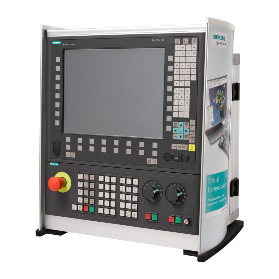
Introduction 1.2 Operator panel fronts Operator panel fronts 1.2.1 Overview Introduction The display (screen) and operation (e.g. hardkeys and softkeys) of the HMI sI user interface occurs via the panel front. In this example, the OP 010 operator panel front is used to illustrate the components that are available for operating the controller and machine tool. -
Page 17: Keys Of The Operator Panel
Introduction 1.2 Operator panel fronts Numerical key group Softkeys Control key group Hotkey group Cursor key group USB interface Menu select key Menu forward button Machine area button Menu back key References An exact description as well as a view of the other serviceable panel fronts may be found in /BH/, 840D sl / 840 Di sl Operator Components Manual 1.2.2 Keys of the operator panel... - Page 18 Introduction 1.2 Operator panel fronts Function Cursor Input focus/cursor between different fields. Navigate rows or characters. Use the right cursor to open a directory or program in the editor. Use the left cursor to switch to a higher level in the directory tree. SELECT Choose one of a number of options presented.
- Page 19 Introduction 1.2 Operator panel fronts Function MACHINE Open the "Machine" operating area. Menu forward key Advance the horizontal softkey bar. MENU SELECT Call the main menu for operating area selection. HMI sl Turning Operating Manual, 01/2008, 6FC5398-7AP10-0BA0...
-
Page 20: Machine Control Panels
1.3.1 Overview The machine tool can be equipped with a machine control panel by Siemens or with a specific machine control panel from the machine manufacturer. You use the machine control panel to initiate actions on the machine tool such as traversing an axis or starting the machining of a workpiece. - Page 21 Introduction 1.3 Machine control panels RESET Stop processing the current programs. • The NCK control remains synchronized with the machine. It is in its initial state and ready for a new program run. Cancel alarm. • Program control SINGLE BLOCK Single block mode on/off.
- Page 22 Introduction 1.3 Machine control panels Direction keys Select the traversing direction. RAPID Traverse axis in rapid traverse while pressing the direction key. WCS MCS Switches between the workpiece coordinate system (WCS = work) and machine coordinate system (MCS = machine). Spindle control with override switch SPINDLE STOP Stop spindle.
-
Page 23: User Interface
Introduction 1.4 User interface User interface 1.4.1 Screen layout Overview Figure 1-3 User interface Active operating area and mode Alarm/message line Program name Channel state and program control Channel operational messages HMI sl Turning Operating Manual, 01/2008, 6FC5398-7AP10-0BA0... -
Page 24: Status Display
Introduction 1.4 User interface Axis position display in actual value window Display for active tool T • current feedrate F • active spindle with current status (S) • Operating window with program block display Display of active G functions, all G functions, H functions and input window for different functions (for example, skip blocks, program control) Dialog line to provide additional user notes Horizontal softkey bar... - Page 25 Introduction 1.4 User interface "Program manager" operating area "Diagnosis" operating area "Start-up" operating area Active mode or submode "Jog" mode "MDA" mode "Auto" mode "Teach In" submode "Repos" submode "Ref Point" submode Alarms and messages Alarm display The alarm numbers are displayed in white lettering on a red background.
- Page 26 Introduction 1.4 User interface Second line Display Description Program path and program name The displays in the second line can be configured. Machine manufacturer Please also refer to the machine manufacturer's instructions. Third line Display Description Display of channel status. If several channels are present on the machine, the channel name is also displayed.
-
Page 27: Actual Value Window
Introduction 1.4 User interface The machine manufacturer settings determine which program controls are displayed. Machine manufacturer Please also refer to the machine manufacturer's instructions. 1.4.3 Actual value window The actual values of the axes and their positions are displayed. WCS/MCS The displayed coordinates are based on either the machine coordinate system or the workpiece coordinate system. -
Page 28: T,F,S Window
Introduction 1.4 User interface Overview of display Display Meaning Header columns WCS/MCS Display of axes in selected coordinate system. Item Position of displayed axes. Display of distance-to-go The distance-to-go for the current NC block is displayed while the program is running. Feed/override The feed acting on the axes, as well as the override, are displayed in the full-screen version. - Page 29 Introduction 1.4 User interface Feed data Display Meaning Feed disable Actual feed value If several axes are traversing, the largest axis feed will be displayed Rapid traverse G0 is active 0.000 No feed is active Override Display as a percentage Spindle data Display Meaning...
-
Page 30: Current Block Display
Introduction 1.4 User interface 1.4.5 Current block display The window of the current block display shows you the program blocks currently being executed. Display of current program The following information is displayed in the running program: ● The workpiece name or program name is entered in the title row. ●... - Page 31 Introduction 1.4 User interface Changing the operating area Press the "MENU SELECT" key and select the desired operating area using the horizontal softkey bar. You can call the "Machine" operating area directly using the key on the operator panel. Select the "Machine" operating area Changing the operating mode You can select a mode or submode directly using the keys on the machine control panel or using the vertical softkeys in the main menu.
-
Page 32: Entering Or Selecting Parameters
Introduction 1.4 User interface 1.4.7 Entering or selecting parameters When setting up the machine and during programming, you must enter values for various parameters in the input fields. The background color of the fields provides information on the status of the input field. Orange background Input field is selected Light orange background... - Page 33 Introduction 1.4 User interface Changing or calculating parameters If you only want to change individual characters in an input field rather than overwriting the entire entry, switch to insertion mode. In this mode, the pocket calculator is also active. You can use it during programming to calculate parameter values.
-
Page 34: Pocket Calculator
Introduction 1.4 User interface 1.4.8 Pocket calculator You can use the pocket calculator to quickly calculate parameter values during programming. If, for example, the diameter of a workpiece is only dimensioned indirectly in the workpiece drawing, i.e., the diameter must be derived from the sum of several other dimension specifications, you can calculate the diameter directly in the input field of this parameter. -
Page 35: Context Menu
Introduction 1.4 User interface Press the "=" softkey. - OR - Press the "Calculate" softkey. - OR - Press the "INPUT" key. The new value is calculated and displayed in the input field of the pocket calculator. Press the "Accept" softkey. The calculated value is accepted and displayed in the input field of the window. -
Page 36: Changing The User Interface Language
Introduction 1.4 User interface Channel switchover You can switch over to the next channel by touching the channel display in the status display. 1.4.11 Changing the user interface language Procedure Select the "Startup" operating area. Press the "Change language" softkey. The "Language selection"... -
Page 37: Editing Asian Characters
Introduction 1.4 User interface 1.4.12 Editing Asian characters You can edit Asian characters. You can select a character by using the Pinyin phonetic notation, which enables Chinese characters to be expressed by combining Latin letters. The editor is available for the following Asian languages: ●... -
Page 38: Protection Levels
Introduction 1.4 User interface Procedure Editing characters Open the screen form and position the cursor on the entry field and press the <Alt +S> keys. The editor is displayed. Enter the desired phonetic notation. Click the "Cursor down" button to access the dictionary. Repeated clicking of the "Cursor down"... - Page 39 ● Tool offsets ● Work offsets ● Setting data ● Program creation / program editing For additional information, please refer to the following documentation: HMI sl / SINUMERIK 840D sl Commissioning Manual Softkeys Startup operating area Protection levels End user...
-
Page 40: Online Help In Hmi Sl
Introduction 1.4 User interface 1.4.14 Online help in HMI sl A comprehensive context-sensitive online help is stored in the control system. ● A brief description is provided for each window and, if required, step-by-step instructions for the operating sequences. ● A detailed help is provided in the editor for every entered G code. You can also display all G functions and take over a selected command directly from the help into the editor. - Page 41 Introduction 1.4 User interface Calling a topic in the table of contents Press the "Table of contents" softkey. Depending on which technology you are using, the "HMI sl Milling", "HMI sl Turning" or "HMI sl Universal" Operating and Commissioning Manuals as well as the "Programming" Manual are displayed. Select the desired manual with the "Cursor down"...
- Page 42 Introduction 1.4 User interface Displaying alarm descriptions and machine data If messages or alarms are pending in the "Alarms", "Messages" or "Alarm Log" window, position the cursor at the appropriate display and press the <Help> or the <F12> key. The associated alarm description is displayed. If you are in the "Startup"...
-
Page 43: Setting Up The Machine
Setting up the machine Switching on and switching off Start-up When the control starts up, the main screen opens according to the operating mode specified by the machine manufacturer. In general, this is the main screen for the "REF POINT" submode. Machine manufacturer Please also refer to the machine manufacturer's instructions. -
Page 44: Approaching A Reference Point
Setting up the machine 2.2 Approaching a reference point Approaching a reference point 2.2.1 Referencing axes Your machine tool can be equipped with an absolute or incremental path measuring system. An incremental path measuring system must be calibrated after being switched on, but an absolute path measuring system does not. -
Page 45: User Agreement
Setting up the machine 2.2 Approaching a reference point Press the "+" or "-" key. The selected axis moves to the reference point. If you have pressed the wrong direction key, the action is not accepted and the axes do not move. A symbol is shown next to the axis if it has been referenced. - Page 46 Setting up the machine 2.2 Approaching a reference point Press the "+" or "-" key. The selected axis moves to the reference point and stops. The coordinate of the reference point is displayed. The axis is marked with Press the "User enable" softkey. The "User Acknowledge"...
-
Page 47: Modes
Setting up the machine 2.3 Modes Modes 2.3.1 General You can work in three different operating modes. "JOG" mode "JOG" mode is used for the following preparatory actions: ● Reference point approach, i.e. calibration of the position measuring system ● Preparing a machine for executing a program in automatic mode, i.e. measuring tools, measuring the workpiece and, if necessary, defining the work offsets used in the program ●... - Page 48 Setting up the machine 2.3 Modes "REPOS" submode The "REPOS" submode is used for repositioning to a defined position. After a program interruption (e.g. to correct tool wear values) move the tool away from the contour in "JOG" mode. The distances traversed in "JOG" mode are displayed in the actual value window as the "Repos"...
-
Page 49: Channel Switchover
Setting up the machine 2.3 Modes Selecting "Teach In" Press the "TEACH IN" key. 2.3.2 Channel switchover It is possible to switch between channels when several are in use. Since individual channels may be assigned to different mode groups, a channel switchover command is also an implicit mode switchover command. -
Page 50: Settings For The Machine
Setting up the machine 2.4 Settings for the machine Settings for the machine 2.4.1 Switching over the coordinate system (MCS/WCS) The coordinates in the actual value display are relative to either the machine coordinate system or the workpiece coordinate system. By default, the workpiece coordinate system is set as a reference for the actual value display. - Page 51 Setting up the machine 2.4 Settings for the machine Machine manufacturer Please also refer to the machine manufacturer's instructions. Proceed as follows Select "JOG" or "AUTO" mode in the "Machine" operating area. Press the menu forward key and the "Settings" softkey. A new vertical softkey bar appears.
-
Page 52: Setting The Work Offset
Setting up the machine 2.4 Settings for the machine 2.4.3 Setting the work offset You can enter a new position value in the actual value display for individual axes when a settable work offset is active. The difference between the position value in the machine coordinate system MCS and the new position value in the workpiece coordinate system WCS is saved permanently in the currently active work offset (e.g. - Page 53 Setting up the machine 2.4 Settings for the machine Resetting the actual value Press the "Delete active WO" softkey. The offset is deleted permanently. NOTICE Irreversible active work offset The current active work offset is irreversibly deleted by this action. Relative actual value Press the "REL actual values"...
-
Page 54: Measuring The Tool
Setting up the machine 2.5 Measuring the tool Measuring the tool 2.5.1 Overview The geometries of the machining tool must be taken into consideration when executing a part program. These are stored as tool offset data in the tool list. Each time the tool is called, the control considers the tool offset data. - Page 55 Setting up the machine 2.5 Measuring the tool Procedure Select "JOG" mode in the "Machine" operating area. Press the "Meas. tool" softkey. Press the "Manual" softkey. Press the "Tool” softkey. Select the tool to be measured in the tool list that opens. The cutting edge position and the radius or diameter of the tool must already be entered in the tool list.
-
Page 56: Measuring A Tool With A Tool Probe
Setting up the machine 2.5 Measuring the tool 2.5.3 Measuring a tool with a tool probe During automatic measuring, you determine the tool dimensions in the directions X and Z with the aid of a probe. The tool offset data is then calculated from the known position of the tool carrier reference point and the probe. -
Page 57: Calibrating The Tool Probe
Setting up the machine 2.5 Measuring the tool Press the "CYCLE START" key. The automatic measuring process is started, i.e. the tool is traversed at the measurement feedrate to the probe and back again. The tool length is calculated and entered in the tool list. Whereby the cutting edge position and tool radius or diameter are automatically taken into consideration as well. - Page 58 Setting up the machine 2.5 Measuring the tool Press the "X" or "Z" softkey, depending on which point of the tool probe you wish to determine first. Select the direction (+ or -), in which you would like to approach the tool probe.
-
Page 59: Measuring The Workpiece Zero
Setting up the machine 2.6 Measuring the workpiece zero Measuring the workpiece zero The reference point for programming a workpiece is always the workpiece zero. To determine this zero point, measure the length of the workpiece and save the position of the cylinder's face surface in the direction Z in a work offset. - Page 60 Setting up the machine 2.6 Measuring the workpiece zero Select "Work offset" and the work offset (G54...G599) in which you want to store the zero point in the associated selection box. The selection of work offsets can differ. Please refer to the machine manufacturer's specifications. - OR - Select "Basic reference"...
-
Page 61: Work Offsets
Setting up the machine 2.7 Work offsets Work offsets 2.7.1 Overview - work offsets Following reference point approach, the actual value display for the axis coordinates is based on the machine zero (M) of the machine coordinate system (MCS). The program for machining the workpiece, however, is based on the workpiece zero (W) of the workpiece coordinate system (WCS). -
Page 62: Display Active Zero Offset
Setting up the machine 2.7 Work offsets Coarse and fine offsets Every work offset (G54 to G57, G505 to G599) consists of a coarse offset and a fine offset. You can call the work offsets from any program (coarse and fine offsets are added together). You can save the workpiece zero, for example, in the coarse offset, and then store the offset that occurs when a new workpiece is clamped between the old and the new workpiece zero in the fine offset. -
Page 63: Displaying And Editing Base Zero Offset
Setting up the machine 2.7 Work offsets Procedure Select the "Parameter" operating area. Press the "Work offset" softkey. The "Work Offset - Active" window is opened. Note Further details on work offsets If you would like to see further details about the specified offsets or if you would like to change values for the rotation, scaling or mirroring, press the "Details"... -
Page 64: Displaying And Editing Settable Zero Offset
Setting up the machine 2.7 Work offsets Note Activate base offsets The offsets specified here are immediately active. 2.7.4 Displaying and editing settable zero offset All settable offsets, divided into coarse and fine offsets, are displayed in the "Work Offset - G54..G599"... -
Page 65: Displaying And Editing Details Of The Zero Offsets
Setting up the machine 2.7 Work offsets 2.7.5 Displaying and editing details of the zero offsets For each work offset, you can display and edit all data for all axes. You can also delete work offsets. For every axis, values for the following data will be displayed: ●... -
Page 66: Deleting A Work Offset
Setting up the machine 2.7 Work offsets Press the "Clear offset" softkey to reset all entered values. Press the "WO +" or "WO -" softkey to select the next or previous offset, respectively, within the selected area ("Active", "Base", "G54 to G599") without first having to switch to the overview window. -
Page 67: Measuring The Workpiece Zero
Setting up the machine 2.7 Work offsets Press the "Details" softkey. Position the cursor on the zero offset you would like to delete. Press the "Clear Offset" soft key. 2.7.7 Measuring the workpiece zero Procedure Select the "Parameter" operating area and press the "Work offset" softkey. -
Page 68: Monitoring Axis And Spindle Data
Setting up the machine 2.8 Monitoring axis and spindle data Monitoring axis and spindle data 2.8.1 Specify working area limitations The "Working area limitation" function can be used to limit the range within which a tool can traverse in all channel axes. These commands allow you to set up protection zones in the working area which are out of bounds for tool movements. -
Page 69: Editing Spindle Data
Setting up the machine 2.8 Monitoring axis and spindle data 2.8.2 Editing spindle data The speed limits set for the spindles that must not be under- or overshot are displayed in the "Spindles" window. You can limit the spindle speeds in fields "Minimum" and "Maximum" within the limit values defined in the relevant machine data. -
Page 70: Manual Mode
Setting up the machine 2.9 Manual mode Manual mode 2.9.1 General Always use "JOG" mode when you want to set up the machine for the execution of a program or to carry out simple traversing movements on the machine: ● Synchronize the measuring system of the controller with the machine (reference point approach) ●... - Page 71 Setting up the machine 2.9 Manual mode Display Meaning Input of the tool (name or location number) You can select a tool from the tool list via the "Tool" softkey. Cutting edge number of the tool (1 - 9) Spindle Spindle selection, identification with spindle number Spindle M function Spindle off: Spindle is stopped...
-
Page 72: Selecting A Tool
Setting up the machine 2.9 Manual mode 2.9.2.2 Selecting a tool Procedure Select the "T, S, M" softkey in "JOG" mode. Press the "T, S, M" softkey. Enter the name or the number of the tool T in the entry field. - OR - Press the "Tool"... -
Page 73: Starting And Stopping The Spindle Manually
Setting up the machine 2.9 Manual mode 2.9.2.3 Starting and stopping the spindle manually Procedure Select the "T, S, M" softkey in "JOG" mode. Select the desired spindle (e.g. S1) and enter the desired spindle speed or cutting speed in the right-hand entry field. The spindle remains stationary. -
Page 74: Positioning The Spindle
Setting up the machine 2.9 Manual mode 2.9.2.4 Positioning the spindle Procedure Select the "T, S, M" softkey in "JOG" mode. Select the "Stop Pos." setting in the "Spindle M function" field. The "Stop Pos." entry field appears. Enter the desired spindle stop position. The spindle position is specified in degrees. -
Page 75: Traverse Axes By A Defined Increment
Setting up the machine 2.9 Manual mode 2.9.3.1 Traverse axes by a defined increment You can traverse the axes in manual mode via the Increment and Axis keys or handwheels. Proceed as follows Select the "Machine" operating area. Press the "JOG" key. Press keys 1, 10, etc. -
Page 76: Traversing Axes By A Variable Increment
Setting up the machine 2.9 Manual mode Machine manufacturer Please also refer to the machine manufacturer's instructions. 2.9.3.2 Traversing axes by a variable increment Proceed as follows Select the "Machine" operating area. Press the "JOG" key. Press the "Settings" softkey. The "Settings for manual operation"... -
Page 77: Positioning Axes
Setting up the machine 2.9 Manual mode 2.9.4 Positioning axes In order to implement simple machining sequences, you can traverse the axes to certain positions in manual mode. The feedrate / rapid traverse override is active during traversing. Procedure If required, select a tool. Select the "JOG"... - Page 78 Setting up the machine 2.9 Manual mode Proceed as follows Select the "Machine" operating area. Press the "JOG" key. Press the menu forward key and the "Settings" softkey. The "Settings for manual operation" window is opened. See also Switching the unit of measurement (Page 50) HMI sl Turning Operating Manual, 01/2008, 6FC5398-7AP10-0BA0...
-
Page 79: Handwheel Assignment
Setting up the machine 2.10 Handwheel assignment 2.10 Handwheel assignment You can traverse the axes in the machine coordinate system (MCS) or in the workpiece coordinate system (WCS) via the handwheel. All axes are provided in the following order for handwheel assignment: ●... - Page 80 Setting up the machine 2.10 Handwheel assignment To open the "Axis" selection box using the "INSERT" key, navigate to the desired axis, and press the "INPUT" key. Selecting an axis also activates the handwheel (e.g., "X" is assigned to handwheel no. 1 and is activated immediately). Press the "Handwheel"...
-
Page 81: Mda
Setting up the machine 2.11 MDA 2.11 In "MDA" mode (Manual Data Automatic mode), you can enter G-code commands block-by- block and immediately execute them for setting up the machine. You can load an MDA program straight from the Program Manager into the MDA buffer. You may also store programs which were rendered or changed in the MDA operating window into any directory of the Program Manager. -
Page 82: Saving An Mda Program
Setting up the machine 2.11 MDA 2.11.2 Saving an MDA program Proceed as follows Select the "Machine" operating area. Press the "MDA" key. The MDA editor opens. Create the MDA program by entering the G-code commands using the operator's keyboard. Press the "Store MDA"... -
Page 83: Executing An Mda Program
Setting up the machine 2.11 MDA 2.11.3 Executing an MDA program Proceed as follows Select the "Machine" operating area. Press the "MDA" key. The MDA editor opens. Input the desired G-code commands using the operator’s keyboard. Press the "CYCLE START" key. The control executes the input blocks. -
Page 84: Deleting An Mda Program
Setting up the machine 2.11 MDA 2.11.4 Deleting an MDA program Requirement The MDA editor contains a program that you created in the MDI window or loaded from the program manager. Procedure Press the "Delete MDI buffer" softkey. The program displayed in the program window is deleted. HMI sl Turning Operating Manual, 01/2008, 6FC5398-7AP10-0BA0... -
Page 85: Machining The Workpiece
Machining the workpiece Starting machining 3.1.1 Starting and stopping machining During execution of a program, the workpiece is machined in accordance with the programming on the machine. After the program is started in automatic mode, workpiece machining is performed automatically. Requirements The following requirements must be met before executing a program: ●... - Page 86 Machining the workpiece 3.1 Starting machining Note Starting the program in any operating area If the control is in "AUTO" mode, you can also start the selected program when you are in any operating area. Stopping machining Press the "CYCLE STOP" key. Machining stops immediately.
-
Page 87: Selecting A Program
Machining the workpiece 3.1 Starting machining 3.1.2 Selecting a program Proceed as follows Select the "Program manager" operating area. The directory overview is opened. Place the cursor on the directory containing the program that you want to select. Press the “INPUT” key - OR - Press the "Cursor right"... -
Page 88: Executing A Trail Program Run
Machining the workpiece 3.2 Executing a trail program run Executing a trail program run 3.2.1 Executing single blocks When testing a program, the system can interrupt the machining of the workpiece after each program block, which triggers a movement or auxiliary function on the machine. In this way, you can control the machining result block-by-block during the initial execution of a program on the machine. -
Page 89: Displaying The Current Program Block
Machining the workpiece 3.3 Displaying the current program block Press the "SINGLE BLOCK" key again, if the machining is not supposed to run block-by-block. The key is deselected again. If you now press the "CYCLE START" key again, the program is executed to the end without interruption. -
Page 90: Displaying A Basic Block
Machining the workpiece 3.3 Displaying the current program block 3.3.2 Displaying a basic block If you want precise information about axis positions and important G functions during testing or program execution, you can call up the basic block display. This is how you can check, when using cycles, for example, whether the machine is actually traversing. -
Page 91: Display Program Level
Machining the workpiece 3.3 Displaying the current program block 3.3.3 Display program level You can display the current program level during the execution of a large program with several subprograms. Display of program level The following information will be displayed: ●... -
Page 92: Correcting A Program
Machining the workpiece 3.4 Correcting a program Correcting a program As soon as a syntax error in the part program is detected by the controller, program execution is interrupted and the syntax error is displayed in the alarm line. Correction possibilities Depending on the state of the control system, you can make the following corrections using the Program editing function. -
Page 93: Repositioning Axes
Machining the workpiece 3.5 Repositioning axes Note Exit the editor using the "Close" softkey to return to the "Program manager" operating area. Repositioning axes After a program interruption in automatic mode (e.g. after a tool breaks) you can move the tool away from the contour in manual mode. - Page 94 Machining the workpiece 3.5 Repositioning axes Proceed as follows Press the "REPOS" key. Select the axes to be traversed one after the other. Press the "+" or "-" key for the relevant direction. The axes are moved to the interrupt position. HMI sl Turning Operating Manual, 01/2008, 6FC5398-7AP10-0BA0...
-
Page 95: Starting Machining At A Specific Point
Machining the workpiece 3.6 Starting machining at a specific point Starting machining at a specific point 3.6.1 Use block search If you would only like to perform a certain section of a program on the machine, then you need not start the program from the beginning. You can also start the program from a specified program block. - Page 96 Machining the workpiece 3.6 Starting machining at a specific point Cascaded search You can start another search from the "Search target found" state. The cascading can be continued any number of times after every search target found. Note Another cascaded block search can be started from the stopped program execution only if the search target has been found.
-
Page 97: Continuing Program From Search Target
Machining the workpiece 3.6 Starting machining at a specific point 3.6.2 Continuing program from search target To continue the program at the desired position, press the "CYCLE START" key twice. ● The first CYCLE START outputs the auxiliary functions collected during the search. The program is then in the Stop state. -
Page 98: Defining An Interruption Point As Search Target
Machining the workpiece 3.6 Starting machining at a specific point 3.6.4 Defining an interruption point as search target Requirement A program was selected in "AUTO" mode and interrupted during execution through "CYCLE STOP" or "RESET". Procedure Press the "Block search" softkey. Press the "Interrupt point"... -
Page 99: Entering The Search Target Via Search Pointer
Machining the workpiece 3.6 Starting machining at a specific point 3.6.5 Entering the search target via search pointer Enter the program point which you would like to proceed to in the "Search Pointer" window. Requirement The program is selected and the controller is in Reset mode. Screen form Each line represents one program level. -
Page 100: Parameters For Block Search In The Search Pointer
Machining the workpiece 3.6 Starting machining at a specific point Note Interruption point You can load the interruption point in search pointer mode. 3.6.6 Parameters for block search in the search pointer Parameter Meaning Number of program level Program: The name of the main program is automatically entered Ext: File extension Pass counter... - Page 101 Machine manufacturer Please refer to the machine manufacturer's specifications. References For additional information, please refer to the following documentation: HMI sl / SINUMERIK 840D sl Commissioning Manual Procedure Select the "Machine" operating area. Press the "AUTO" key. Press the "Block search" and "Block search mode" softkeys.
-
Page 102: Intervening In The Program Sequence
Machining the workpiece 3.7 Intervening in the program sequence Intervening in the program sequence 3.7.1 Program control You can change the program sequence in the "AUTO" and "MDA" modes. Abbreviation/program Scope control The program is started and executed with auxiliary function outputs and dwell times. In this mode, the axes are not traversed. - Page 103 Machining the workpiece 3.7 Intervening in the program sequence Activating program control You can control the program sequence however you wish by selecting and clearing the relevant check boxes. Display / response of active program controls: If a program control is activated, the abbreviation of the corresponding function appears in the status display as response.
-
Page 104: Skip Blocks
Machining the workpiece 3.7 Intervening in the program sequence 3.7.2 Skip blocks It is possible to skip program blocks, which are not to be executed every time the program runs. The skip blocks are identified by placing a "/" (forward slash) or "/x (x = number of skip level) character in front of the block number. -
Page 105: Overstore
Machining the workpiece 3.8 Overstore Press the "Prog. cntrl." and "Skip blocks" softkeys. The "Program control" window appears and shows a list of block levels. Overstore This function allows you to overstore technological parameters (for example, auxiliary functions, axis feed, spindle speed, programmable instructions, etc.) for a program run in the main memory of the NCK. - Page 106 Machining the workpiece 3.8 Overstore Press the <CYCLE START> key. The blocks you have entered are stored. You can observe execution in the "Overstore" window. After the entered blocks have been executed, you can append blocks again. You cannot change the operating mode while you are in overstore mode.
-
Page 107: Editing A Program
Machining the workpiece 3.9 Editing a program Editing a program 3.9.1 Overview - program editor With the editor, you are able to render, supplement, or change part programs. Note The maximum block length is 512 characters. Calling the editor ● The editor is started via the "Program correction" function in the "Machine" operating area. -
Page 108: Searching In Programs
Machining the workpiece 3.9 Editing a program 3.9.2 Searching in programs You can use the search function to quickly arrive at points where you would like to make changes, e.g. in very large programs. Requirement The desired program is opened in the editor. Procedure Press the "Search"... -
Page 109: Exchanging Program Text
Machining the workpiece 3.9 Editing a program 3.9.3 Exchanging program text You can find and replace text in one step. Requirement The desired program is opened in the editor. Proceed as follows Press the "Search" softkey. A new vertical softkey bar appears. Press the "Find + replace"... -
Page 110: Copying/Pasting/Deleting A Program Block
Machining the workpiece 3.9 Editing a program 3.9.4 Copying/pasting/deleting a program block Requirement The program is opened in the editor. Procedure Press the "Mark" softkey. - OR - Press the "SELECT" key. Select the desired program blocks with the cursor or mouse. Press the "Copy"... -
Page 111: Renumbering A Program
Machining the workpiece 3.9 Editing a program 3.9.5 Renumbering a program You can modify the block numbering of programs opened in the editor at a later point in time. Requirement The program is opened in the editor. Procedure Press the ">>" softkey. A new vertical softkey bar appears. -
Page 112: Editing A Cycle Call
Machining the workpiece 3.9 Editing a program 3.9.6 Editing a cycle call You have called the desired cycle via softkey in the program editor, entered the parameters and confirmed with "Accept". The cycle is transferred to the editor as G code. The cycle parameterized in G code has a light gray background and is write-protected. -
Page 113: Editor Settings
Machining the workpiece 3.9 Editing a program 3.9.7 Editor settings Enter the default settings in the "Settings" window that are to take effect automatically when the editor is opened. Presettings Settings Meaning Number Yes: A new block number will automatically be assigned after every line automatically change. - Page 114 Machining the workpiece 3.9 Editing a program Procedure Select the "Program" operating area You have activated the editor. Press the ">>" and "Settings" softkeys. The "Settings" window appears. Make the desired changes here and press the "OK" softkey to confirm your settings.
-
Page 115: Simulating A Machining Operation
Machining the workpiece 3.10 Simulating a machining operation 3.10 Simulating a machining operation 3.10.1 Overview During simulation, the current program is calculated in its entirety and the result displayed in graphic form. The result of programming is verified without traversing the machine axes. Incorrectly programmed machining steps are detected at an early stage and incorrect machining on the workpiece prevented. - Page 116 Machining the workpiece 3.10 Simulating a machining operation Views The following views are available for all three variants: ● Side view ● 3D view ● 4-window view ● 2-window view Status display The current axis coordinates, the override, the current tool with cutting edge, the current program block, the feedrate and the machining time are displayed.
-
Page 117: Simulation Before Machining Of The Workpiece
Machining the workpiece 3.10 Simulating a machining operation 3.10.2 Simulation before machining of the workpiece Before machining the workpiece on the machine, you have the option of performing a quick run-through in order to graphically display how the program will be executed. This provides a simple way of checking the result of the programming. -
Page 118: Simultaneous Recording Before Machining Of The Workpiece
Machining the workpiece 3.10 Simulating a machining operation Press the "Simulation" and "Start" softkeys. The program execution is displayed graphically on the screen. The machine axes do not move. Press the "Stop" softkey if you wish to stop the simulation. - OR - Press the "Reset"... -
Page 119: Starting Simultaneous Recording
Machining the workpiece 3.10 Simulating a machining operation 3.10.3.1 Starting simultaneous recording Procedure Load a program in the "AUTO" mode. Press the "Prog. ctrl." softkey and activate the checkboxes "PRT no axis movement" and "DRY run feedrate". The program is executed without axis movement. The programmed feedrate is replaced by a dry run feedrate. -
Page 120: Different Views Of A Workpiece
Machining the workpiece 3.10 Simulating a machining operation Procedure Load a program in the "AUTO" mode. Press the "Sim. rec." softkey. Press the <CYCLE START> key. The machining of the workpiece is started and graphically displayed on the screen. Press the "Sim. rec." softkey again to stop the recording. 3.10.5 Different views of a workpiece In the graphical display, you can choose between different views so that you constantly have... -
Page 121: 3D View
Machining the workpiece 3.10 Simulating a machining operation 3.10.5.2 3D view Start the simulation. Press the "3D view" softkey. Changing the display You can increase or decrease the size of the simulation graphic, move it, turn it, or change the segment. 3.10.5.3 4-window Start the simulation. -
Page 122: Graphical Display
Machining the workpiece 3.10 Simulating a machining operation Changing the display You can increase or decrease the size of the simulation graphic and move it, as well as change the segment. 3.10.6 Graphical display Figure 3-1 4-window view Active window The currently active window has a lighter background than the other view windows. -
Page 123: Editing The Simulation Display
Machining the workpiece 3.10 Simulating a machining operation 3.10.7 Editing the simulation display 3.10.7.1 Blank display You can change the blank defined in the program. Procedure The simulation or the simultaneous recording is started. Press the ">>" and "Blank" softkeys. The "Blank Input"... -
Page 124: Program Control During The Simulation
Machining the workpiece 3.10 Simulating a machining operation 3.10.8 Program control during the simulation 3.10.8.1 Changing the feedrate You can change the feedrate at any time during the simulation. You can track the changes in the dialog line. Note If you are working with the "Simultaneous recording" function, the override rotary switch on the control panel is used. -
Page 125: Simulating The Program Block By Block
Machining the workpiece 3.10 Simulating a machining operation 3.10.8.2 Simulating the program block by block You can control the program execution during simulation, i.e. execute a program block by block, as when executing a program. Procedure Simulation is started. Press the "Program control" and "Single block" softkeys. Press the "<<"... -
Page 126: Editing And Adapting A Simulation Graphic
Machining the workpiece 3.10 Simulating a machining operation 3.10.9 Editing and adapting a simulation graphic 3.10.9.1 Enlarging or reducing the graphical representation Requirement The simulation or the simultaneous recording is started. Procedure Press the <+> and <-> keys if you want to enlarge or reduce the graphical representation now displayed. -
Page 127: Panning A Graphical Representation
Machining the workpiece 3.10 Simulating a machining operation 3.10.9.2 Panning a graphical representation Requirement The simulation or the simultaneous recording is started. Procedure Press a cursor key if you want to move the graphic up, down, left, or right. 3.10.9.3 Rotating the graphical representation In the 3D view and in the 4-window view, you can rotate the workpiece to view it from all sides. -
Page 128: Modifying The Viewport
Machining the workpiece 3.10 Simulating a machining operation 3.10.9.4 Modifying the viewport If you would like to move, enlarge or decrease the size of the segment of the graphical display, e.g. to view details or display the complete workpiece, use the magnifying glass. Using the magnifying glass, you can define your own segment and then increase or decrease its size. - Page 129 Machining the workpiece 3.10 Simulating a machining operation Requirement Simulation is running and an alarm is active. Procedure Press the "Program control" and "Alarm" softkeys. The "Simulation Alarms" window is opened and a list of all pending alarms is displayed. Press the "Acknowledge alarm"...
-
Page 130: Displaying G Functions And Auxiliary Functions
Machining the workpiece 3.11 Displaying G functions and auxiliary functions 3.11 Displaying G functions and auxiliary functions 3.11.1 Selected G functions 16 selected G groups are displayed in the "G Function" window. Within a G group, the G function currently active in the controller is displayed. Some G codes (e.g. - Page 131 Machining the workpiece 3.11 Displaying G functions and auxiliary functions G groups displayed by default (ISO code) Group Meaning G group 1 Modally active motion commands (e.g. G0, G1, G2, G3) G group 2 Non-modally active motion commands, dwell time (e.g. G4, G74, G75) G group 3 Programmable offsets, working area limitations and pole programming (e.g.
-
Page 132: All G Functions
Machining the workpiece 3.11 Displaying G functions and auxiliary functions Machine manufacturer Please refer to the machine manufacturer's specifications. References For more information about configuring the displayed G groups, refer to the following document: HMI sl / 840D sl Commissioning Manual 3.11.2 All G functions All G groups and their group numbers are listed in the "G Functions"... -
Page 133: Auxiliary Functions
Machining the workpiece 3.11 Displaying G functions and auxiliary functions Procedure Select the "Machine" operating area. Press the "JOG", "AUTO", or "MDA" key. Press the ">>" and "All G functions" softkeys. The "G Functions" window is opened. 3.11.3 Auxiliary functions Auxiliary functions include M and H functions preprogrammed by the machine manufacturer, which transfer parameters to the PLC to trigger reactions defined by the manufacturer. - Page 134 Machining the workpiece 3.11 Displaying G functions and auxiliary functions Press the "H functions" softkey. The "Auxiliary Functions" window opens. Press the "H functions" softkey again to hide the window again. You can display status information for diagnosing synchronized actions in the "Synchronized Actions"...
-
Page 135: Displaying The Program Runtime And Counting Workpieces
Machining the workpiece 3.12 Displaying the program runtime and counting workpieces Procedure Select the "Machine" operating area. Press the "AUTO" key. Press the menu forward key and the "Synchron." softkey. The "Synchronized Actions" window appears. 3.12 Displaying the program runtime and counting workpieces To gain an overview of the program runtime and the number of machined workpieces, open the "Times, Counter"... - Page 136 Machining the workpiece 3.12 Displaying the program runtime and counting workpieces If you are executing the program from an external location, the program loading progress is displayed here. ● Influencing the time measurement The time measurement is started with the start of the program and ends with the end of the program (M30) or with an agreed M function.
-
Page 137: Setting For Automatic Mode
Machining the workpiece 3.13 Setting for automatic mode 3.13 Setting for automatic mode 3.13.1 Defining the dry run feedrate Before machining a workpiece, test the program without moving the machine axes. This allows for early detection of programming errors. For this test, you can use a dry run feedrate that you have defined. - Page 138 Machining the workpiece 3.13 Setting for automatic mode HMI sl Turning Operating Manual, 01/2008, 6FC5398-7AP10-0BA0...
-
Page 139: Programming A Cycle
Programming a cycle The program editor offers graphical programming for the creation of a DIN code program. Functions The following functionality is available: ● Technology-oriented cycle selection via softkeys ● Input windows for parameter assignment with animated help screens ● Context-sensitive online help for every input window ●... - Page 140 Programming a cycle 4.1 Creating a program Select the file type (MPF or SPF), enter the desired name of the program and press the "OK" softkey or the "Input" key. This editor is opened. Enter the desired G code commands. Calling a tool Press the "Tool"...
-
Page 141: Selection Of The Cycles Via Softkey
Programming a cycle 4.2 Selection of the cycles via softkey Selection of the cycles via softkey Overview of the machining steps The following machining steps are available: ⇒ ⇒ ⇒ ⇒ ⇒ ⇒ ⇒ ⇒ HMI sl Turning Operating Manual, 01/2008, 6FC5398-7AP10-0BA0... - Page 142 Programming a cycle 4.2 Selection of the cycles via softkey ⇒ ⇒ ⇒ ⇒ ⇒ ⇒ ⇒ ⇒ See also General (Page 151) HMI sl Turning Operating Manual, 01/2008, 6FC5398-7AP10-0BA0...
-
Page 143: Fundamentals
Programming a cycle 4.3 Fundamentals Fundamentals 4.3.1 General HMI sl is an operating and programming software for turning machines that makes it easy for you to operate a machine and to program workpieces. The programming of the workpiece is graphically supported (help graphics). The parameter area in the entry field for the cycle program creation is divided into three main columns below the screen name: ●... -
Page 144: Hiding Cycle Parameters
Programming a cycle 4.3 Fundamentals 4.3.3 Hiding cycle parameters The documentation describes all the possible input parameters for each cycle. Depending on the settings of the machine manufacturer, certain parameters can be hidden in the screens, i.e. not displayed. These are then generated with the appropriate default values when the cycles are called. - Page 145 Programming a cycle 4.3 Fundamentals Machining feedrate When the technologies have been programmed, the positions are specified. Various positioning patterns are available (see Section "Positions and position patterns"). This sequence, first technology block and then positioning block must be adhered to. Example of MCALL N20 G17 G54 G71 G0 Z200...
-
Page 146: Checking Cycle Parameters During The Programming And The Cycle Execution
Programming a cycle 4.3 Fundamentals 4.3.6 Checking cycle parameters during the programming and the cycle execution The entered parameters are already checked during the program creation in order to avoid faulty entries. If a parameter is assigned an illegal value, this is indicated in the input screen by an orange background and by an error text in a comment line. -
Page 147: Setting Data For Cycles
Programming a cycle 4.3 Fundamentals ● The following text is also displayed when the cursor is placed on the parameter entry field: The programming can only be completed after the incorrect value has been corrected. Faulty parameter values are also monitored with alarms during the cycle runtime. 4.3.7 Setting data for cycles The machine data for the technology selection is created for a specific channel as it is... - Page 148 Programming a cycle 4.3 Fundamentals The plane for the standard screens can be permanently set via cycle machine data. The corresponding line in the screens is then omitted: ● MD52006 $MCS_DISP_PLANE_TURN: – 0 = plane selection in the user interface –...
-
Page 149: Cycles That Can Be Recompiled
Programming a cycle 4.3 Fundamentals 4.3.8 Cycles that can be recompiled Programs (e.g. from SINUMERIK 802Dsl), in which the following cycles are called, can still be executed. These cycles can be recompiled in screens and changed. Cycle Function CYCLE87 Compatibility 802Dsl – Boring 3 CYCLE88 Compatibility 802Dsl –... -
Page 150: Blank Input
Programming a cycle 4.3 Fundamentals 4.3.10 Blank input Function The blank is used for the simulation and the simultaneous recording. A useful simulation can only be achieved with a blank that is as close as possible to the real blank. Create a separate program for each new workpiece that you would like to produce. -
Page 151: Drilling
Programming a cycle 4.4 Drilling Parameter Description Unit Number of edges – (only for polygon) SW or L Width across flats or edge length – (only for polygon) Width of the blank - (only for centered cuboid) Length of the blank - (only for centered cuboid) Drilling 4.4.1 General... -
Page 152: Centering - Cycle81
Programming a cycle 4.4 Drilling – Diameter (centering in relation to the diameter, only for CYCLE81) The diameter of the centering hole is programmed at Z1. In this case, the tip angle of the tool must be specified in the tool list. The drill is inserted into the workpiece until the specified diameter is reached. - Page 153 Programming a cycle 4.4 Drilling Procedure Select the part program to be edited in the "Program manager" operating area. Press the "Open" softkey or the "INPUT" key to edit the part program in the editor. Press the "Drilling" softkey. Press the "Centering" softkey. The "Centering"...
-
Page 154: Drilling - Cycle82
Programming a cycle 4.4 Drilling Parameter Description Unit Diameter (centered with reference to the diameter) Centering • The angle for the center drill entered in the tool list is applied. Tip (centered with reference to the depth) • The drill is inserted into the workpiece until the programmed insertion depth is reached. - Page 155 Programming a cycle 4.4 Drilling Press the "Open" softkey or the "INPUT" key to edit the part program in the editor. Press the "Drilling" softkey. Press the "Drilling Reaming" softkey. Press the "Drilling" softkey. The "Drilling" input window opens. Help screens Help with selection of parameter RP, for example.
-
Page 156: Reaming - Cycle85
Programming a cycle 4.4 Drilling Parameter Description Unit Shank (drilling depth in relation to the shank) Drilling depth • The drill is inserted into the workpiece until the drill shank reaches the value programmed for Z1. The angle entered in the tool list is taken into account. •... - Page 157 Programming a cycle 4.4 Drilling Press the "Open" softkey or the "INPUT" key to edit the part program in the editor. Press the "Drilling" softkey. Press the "Drilling Reaming" softkey. Press the "Reaming" softkey. The "Reaming" input window opens. Help screens Help with selection of parameter RP, for example.
-
Page 158: Deep-Hole Drilling - Cycle83
Programming a cycle 4.4 Drilling Parameter Description Unit Feedrate during retraction mm/min Reference point Z Drilling depth (abs) or drilling depth in relation to Z0 (inc) It is inserted into the workpiece until it reaches Z1. Dwell time at final drilling depth in seconds •... - Page 159 Programming a cycle 4.4 Drilling 3. Dwell time at drilling depth DTB. 4. The tool retracts from the workpiece for the stock removal with rapid traverse to the safety clearance. 5. Dwell time at starting point DTS. 6. Approach of the last drilling depth with G0, reduced by the clearance distance V3. 7.
- Page 160 Programming a cycle 4.4 Drilling Procedure Select the part program to be edited in the "Program manager" operating area. Press the "Open" softkey or the "INPUT" key to edit the part program in the editor. Press the "Drilling" softkey. Press the "Deep-hole drilling" softkey. The "Deep-hole Drilling"...
- Page 161 Programming a cycle 4.4 Drilling Parameters Parameter Description Unit Machining plane: G17 (XY) Retraction plane (abs) Safety clearance (inc) Single position Machining • position Drill hole at programmed position. Position pattern • Position with MCALL Stock removal Machining • The drill is retracted from the workpiece for stock removal. Chipbreaking •...
-
Page 162: Boring - Cycle86
Programming a cycle 4.4 Drilling Parameter Description Unit Clearance distance – (for stock removal only and manual clearance distance) Distance to the last infeed depth that the drill approaches in rapid traverse after stock removal. Dwell time at drilling depth in seconds •... - Page 163 Programming a cycle 4.4 Drilling Approach/retraction 1. The tool moves with G0 to safety clearance of the reference point. 2. Travel to the final drilling depth with G1 and the speed and feedrate programmed before the cycle call. 3. Dwell time at final drilling depth. 4.
- Page 164 Programming a cycle 4.4 Drilling Parameters Parameter Description Unit Machining plane: G17 (XY) Retraction plane (abs) Safety clearance (inc) Single position Machining • position Drill hole at programmed position. Position pattern • Position with MCALL Direction of rotation • • Reference point Z Drilling depth (abs) or drilling depth in relation to Z0 (inc) Dwell time at final drilling depth in seconds...
-
Page 165: Tapping - Cycle84, 840
Programming a cycle 4.4 Drilling 4.4.7 Tapping - CYCLE84, 840 Function You can machine an internal thread with the "tapping" cycle. The tool moves to the safety clearance with the active speed and rapid traverse. The spindle stops, spindle and feedrate are synchronized. The tool is then inserted in the workpiece with the programmed speed (dependent on %S). - Page 166 Programming a cycle 4.4 Drilling 4. Spindle stop and dwell time at drilling depth. 5. Spindle reverse after dwell time has elapsed. 6. Retraction with active spindle retraction speed (dependent on %S) to safety clearance 7. Spindle stop. 8. Retraction to retraction plane with G0. Approach/retraction during stock removal 1.
- Page 167 Programming a cycle 4.4 Drilling Procedure Select the part program to be edited in the "Program manager" operating area. Press the "Open" softkey or the "INPUT" key to edit the part program in the editor. Press the "Drilling" softkey. Press the "Thread" softkey. The "Tapping"...
- Page 168 Programming a cycle 4.4 Drilling Parameters Parameter Description Unit Machining plane: G17 (XY) Retraction plane (abs) Safety clearance (inc) With compensating chuck Compensationg chuck • mode Without compensating chuck • Single position Machining • position Tap hole to programmed position Position pattern •...
- Page 169 Programming a cycle 4.4 Drilling Parameter Description Unit Thread lead in ... mm/rev The pitch is determined by the tool used. in/rev MODULE: Used with endless screws, for example, which extend into a gear • MODULE wheel. Turns/" Turns/": Used with pipe threads, for example. •...
-
Page 170: Positioning And Position Patterns
Programming a cycle 4.4 Drilling 4.4.8 Positioning and position patterns 4.4.8.1 General information Function After you have programmed the technology (cycle call), you must program the positions. Several position patterns are available: ● Arbitrary positions ● Position on a line, on a grid or frame ●... - Page 171 Programming a cycle 4.4 Drilling Procedure Select the part program to be edited in the "Program manager" operating area. Press the "Open" softkey or the "INPUT" key to edit the part program in the editor. Press the "Drilling" softkey. Press the "Positions" and "Arbitrary positions" softkeys. The "Positions"...
-
Page 172: Line Position Pattern - Holes1
Programming a cycle 4.4 Drilling Parameter Parameter Description XY(without A/ or B axis support) Unit Repeat jump label for position Machining plane: G17 (XY) X0: 1st position (abs) Y0: 1st position (abs) X1: 2nd position (abs inc) Y1: 2nd position (abs inc) X2: 3rd position (abs inc) Y2: 3rd position (abs inc) X8: 9th position (abs) - Page 173 Programming a cycle 4.4 Drilling Procedure Select the part program to be edited in the "Program manager" operating area. Press the "Open" softkey or the "INPUT" key to edit the part program in the editor. Press the "Drilling" softkey. Press the "Positions" and "Line" softkeys. The "Position Pattern"...
- Page 174 Programming a cycle 4.4 Drilling Help with selection of the "frame" position pattern parameter. Parameters Parameter Description Unit Repeat jump label for position Machining plane: G17 (XY) Position pattern Selection option for the following patterns: Line • Grid • Frame •...
-
Page 175: Circle Position Pattern - Holes2
Programming a cycle 4.4 Drilling 4.4.8.4 Circle position pattern - HOLES2 Function You can program holes on a full circle or pitch circle with defined radius with the "Circle position pattern" cycle. The basic angle of rotation (α0) for the 1st position is relative to the X axis. - Page 176 Programming a cycle 4.4 Drilling Parameter Parameter Description Unit Repeat jump label for position Machining plane: G17 (XY) Pitch circle Circular pattern • Full circle • Reference point X Reference point Y α0 Starting angle for first position. Degrees Positive angle: Full circle is rotated counterclockwise. Negative angle: Full circle is rotated in clockwise direction.
-
Page 177: Rotate
Programming a cycle 4.5 Rotate Rotate 4.5.1 General In all turning cycles apart from contour turning (CYCLE95), it is possible in the combined roughing and finishing mode to reduce the feedrate during finishing for setting data SD 55500 $SCS_TURN_FIN_FEED_PERCENT in percent. 4.5.2 Stock removal - CYCLE951 Function... - Page 178 Programming a cycle 4.5 Rotate ● Finishing Finishing is performed in the same direction as roughing. The cycle automatically selects and deselects tool radius compensation during finishing. Approach/retraction 1. The tool first moves at rapid traverse to the starting point of the machining operation calculated internally in the cycle (reference point + safety distance).
- Page 179 Programming a cycle 4.5 Rotate Help screens Stock removal 1 Stock removal 2 Stock removal 3 E.g. when selecting parameter SC for roughing Parameters Parameter Description Unit Plane selection: G18 (ZX) Safety clearance (inc) Acts in both axes as allowance at the reference point. Feedrate ∇...
- Page 180 Programming a cycle 4.5 Rotate Parameter Description Unit Reference point in Z (abs) End point X (abs) or end point X in relation to X0 (inc) End point Z (abs) or end point Z in relation to Z0 (inc) Maximum depth infeed – (not for finishing) Finishing allowance in X –...
-
Page 181: Groove - Cycle930
Programming a cycle 4.5 Rotate 4.5.3 Groove - CYCLE930 Function You can use the "Groove" cycle to manufacture symmetrical and asymmetrical grooves on any straight contour elements. You can machine outer or inner grooves in the longitudinal or transverse directions. Use the "Groove width"... - Page 182 Programming a cycle 4.5 Rotate Approach/retraction during finishing 1. The tool first moves to the starting point calculated internally in the cycle at rapid traverse. 2. The tool moves at the machining feedrate down one flank and then along the bottom to the center.
- Page 183 Programming a cycle 4.5 Rotate Help screens Example: Help selecting the SC parameter Parameters Parameter Description Unit Plane selection: G18 (ZX) Safety clearance (inc) Acts in both axes as allowance at the reference point. Feedrate rev/min ∇ (roughing) Machining type •...
- Page 184 Programming a cycle 4.5 Rotate Parameter Description Unit T1 or T2 Groove depth at reference point ∅ (abs) or • Groove depth at reference point (inc) • Groove depth in relation to reference point ∅ (abs) or • Groove depth in relation to reference point (inc) •...
-
Page 185: Undercut Form E And F - Cycle940
Programming a cycle 4.5 Rotate 4.5.4 Undercut form E and F - CYCLE940 Function You can use the "Undercut form E" or "Undercut form F" cycle to turn form E or F undercuts in accordance with DIN 509. Approach/retraction 1. The tool first moves to the starting point calculated internally in the cycle at rapid traverse. 2. - Page 186 Programming a cycle 4.5 Rotate Help screens Undercut form E Undercut form F Help with selection of parameter SC, for example. Parameters of undercut form E Parameter Description Unit Machining plane: G18 (ZX) Safety clearance (inc) Acts in both axes as allowance at the reference point. Feedrate Position Form E machining position:...
- Page 187 Programming a cycle 4.5 Rotate Parameter Description Unit Cross feed ∅ (abs) or cross feed (inc) 1) Parameter description refers to plane G18; plane selection G17 or G19 possible in selection field (MD 52006: $MCS_DISP_PLANE_TURN)! Parameters of undercut form F Parameter Description Unit...
-
Page 188: Thread Undercuts - Cycle940
Programming a cycle 4.5 Rotate 4.5.5 Thread undercuts - CYCLE940 Function You can use the "Thread undercut DIN" or "Thread undercut" cycle to program thread undercuts to DIN 76 for workpieces with a metric ISO thread, or freely definable thread undercuts. - Page 189 Programming a cycle 4.5 Rotate Help screens Example: Help selecting the SC parameter Parameters of thread undercut (DIN 76) Parameter Description Unit Machining plane: G18 (ZX) ∇ (roughing) Machining • ∇∇∇ (finishing) • ∇ + ∇∇∇ (roughing and finishing) • Position Machining position: •...
- Page 190 Programming a cycle 4.5 Rotate Parameter Description Unit Cross feed ∅ (abs) or cross feed (inc) - (only for ∇∇∇ and ∇ + ∇∇∇) Maximum depth infeed – (only for ∇ and ∇ + ∇∇∇) Finishing allowance in X – (only for ∇ and ∇ + ∇∇∇) Finishing allowance in Z –...
-
Page 191: Thread Turning - Cycle99
Programming a cycle 4.5 Rotate 4.5.6 Thread turning - CYCLE99 Function You can use the "Longitudinal thread", "Tapered thread" or "Face thread" cycle to turn external or internal threads with a constant or variable pitch. There may be single or multiple threads. For metric threads (thread pitch P in mm/rev), the cycle assigns a value (calculated on the basis of the thread pitch) to the thread depth H1 parameter. - Page 192 Programming a cycle 4.5 Rotate Procedure for longitudinal thread, tapered thread, or face thread Select the part program to be edited in the "Program manager" operating area. Press the "Open" softkey or the "INPUT" key to edit the part program in the editor.
- Page 193 Programming a cycle 4.5 Rotate Parameters for longitudinal thread Parameter Description Unit Machining plane: G18 (ZX) Thread pitch in mm/revolution • mm/rev in/rev Thread pitch in inch/revolution • threads/" Threads per inch • MODULE Thread pitch in MODULE • Change in thread pitch per revolution - (only for P = mm/rev or in/rev) G = 0: The thread pitch P does not change.
- Page 194 Programming a cycle 4.5 Rotate Parameter Description Unit Thread advance (inc) The starting point for the thread is the reference point (X0, Z0) displaced by the thread advance W. The thread advance can be used if you wish to begin the individual cuts slightly earlier in order to produce a precise start of thread as well.
- Page 195 Programming a cycle 4.5 Rotate Parameter Description Unit Number of threads The threads are distributed evenly across the periphery of the turned part; the first thread is always placed at 0°. Thread changeover depth (inc) First machine all threads in sequence to thread change depth DA, then machine all threads in sequence to depth 2 ·...
- Page 196 Programming a cycle 4.5 Rotate Parameter Description Unit Linear: Infeed (only for ∇ and ∇ • + ∇∇∇) Infeed with constant cutting depth Degressive: • Infeed with constant cutting cross-section Internal thread Thread • External thread • Reference point in X ∅ (abs, always diameter) Reference point in Z (abs) X1 or End point X ∅...
- Page 197 Programming a cycle 4.5 Rotate Parameter Description Unit Finishing allowance in X and Z – (only for ∇ and ∇ + ∇∇∇) Number of noncuts - (only for ∇∇∇ and ∇ + ∇∇∇) Return distance (inc) Multiple • – α0 starting angle offset •...
- Page 198 Programming a cycle 4.5 Rotate Parameter Description Unit Change in thread pitch per revolution - (only for P = mm/rev or in/rev) G = 0: The thread pitch P does not change. G > 0: The thread pitch P increases by the value G per revolution. G <...
- Page 199 Programming a cycle 4.5 Rotate Parameter Description Unit αP Infeed slope as angle – (alternative to infeed slope as flank) Degrees α > 0: Infeed along the rear flank α < 0: Infeed along the front flank α = 0: Infeed at right angle to cutting direction If you wish to infeed along the flanks, the maximum absolute value of this parameter may be half the flank angle of the tool.
-
Page 200: Thread Chain - Cycle98
Programming a cycle 4.5 Rotate 4.5.7 Thread chain - CYCLE98 Function With this cycle, you can produce several concatenated cylindrical or tapered threads with a constant pitch in longitudinal and face machining, all of which can have different thread pitches. There may be single or multiple threads. - Page 201 Programming a cycle 4.5 Rotate Press the "Turning" softkey. Press the "Thread" softkey. The "Thread" input window opens. Press the "Thread chain" softkey. The "Thread Chain" input window opens. Help screens Help with selection of parameter P1, for example. Parameters for thread chain Parameter Description Unit...
- Page 202 Programming a cycle 4.5 Rotate Parameter Description Unit Intermediate point 1 X ∅ (abs) or X1 or X1α • Intermediate point 1 in relation to X0 (inc) or • Degrees Thread taper 1 • Incremental dimensions: The sign is also evaluated. Intermediate point 1 Z (abs) or •...
-
Page 203: Cut-Off Cycle92
Programming a cycle 4.5 Rotate 4.5.8 Cut-off CYCLE92 Function The "Cut-off" cycle is used when you want to cut off dynamically balanced parts (e.g. screws, bolts, or pipes). You can program a chamfer or rounding on the edge of the machined part. You can machine at a constant cutting rate V or speed S up to a depth X1, from which point the workpiece is machined at a constant speed. - Page 204 Programming a cycle 4.5 Rotate Procedure Select the part program to be edited in the "Program manager" operating area. Press the "Open" softkey or the "INPUT" key to edit the part program in the editor. Press the "Turning" softkey. Press the "Cut-off” softkey. The "Cut-off"...
- Page 205 Programming a cycle 4.5 Rotate Parameters Parameter Description Unit Safety clearance (inc) Acts in relation to the retraction plane. The direction in which the safety clearance is active is automatically determined by the cycle. Feedrate Direction of spindle rotation S or V Spindle speed or Constant cutting speed m/min...
-
Page 206: Contour Turning
Programming a cycle 4.6 Contour turning Contour turning 4.6.1 General information Function You can create and machine simple or complex contours with the "Contour turning" cycle. A contour comprises separate contour elements, whereby at least two and up to 100 elements result in a defined contour. -
Page 207: Creating A New Contour
Programming a cycle 4.6 Contour turning 4.6.2 Creating a new contour Function For each contour that you want to cut, you must create a new contour. The first step in creating a contour is to specify a starting point. The cycle automatically defines the end of the contour. -
Page 208: Creating Contour Elements
Programming a cycle 4.6 Contour turning 4.6.3 Creating contour elements Creating contour elements After you have created a new contour and specified the starting point, you can define the individual elements that make up the contour. The following contour elements are available for the definition of a contour: ●... - Page 209 Programming a cycle 4.6 Contour turning Procedure for entering or changing contour elements Select a contour element via softkey. The "Straight Z" input window opens. - OR The "Straight X" input window opens. - OR The "Straight ZX" input window opens. - OR The "Circle"...
- Page 210 Programming a cycle 4.6 Contour turning Parameter Description Unit Z1: Length Z1 DIN thread • Z2: Length Z2 • R1: Radius R1 • R2: Radius R2 • T: Groove depth • P: Pitch Thread • mm/rev Degrees α insertion angle •...
-
Page 211: Changing The Contour
Programming a cycle 4.6 Contour turning Parameter Description Unit Grinding allowance Grinding allowance to right of contour • Grinding allowance to left of contour • Additional command Additional G code commands 4.6.4 Changing the contour Function You can change a previously created contour later. Individual contour elements can be ●... -
Page 212: Contour Call - Cycle62
Programming a cycle 4.6 Contour turning Procedure for deleting a contour element Place the cursor on the contour element that you want to delete. Press the "Delete element" softkey. Press the "Delete" softkey. 4.6.5 Contour call - CYCLE62 Function The input creates a reference to the selected contour. There are four ways to call the contour: ●... -
Page 213: Stock Removal
Programming a cycle 4.6 Contour turning Parameters Parameter Description Unit Contour name Contour selection • Labels • Subprogram • Labels in the subprogram • Contour name CON: Contour name LAB1: Label 1 Labels • LAB2: Label 2 • Subprogram PRG: Subprogram PRG: Subprogram Labels in the •... - Page 214 Programming a cycle 4.6 Contour turning Feed interruption To prevent the occurrence of excessively long chips during machining, you can program a feed interruption. Parameter DI specifies the distance after which the feed interruption should occur. Machining type You can select the machining mode (roughing or finishing). During contour roughing, parallel cuts of maximum programmed infeed depth are created.
- Page 215 Programming a cycle 4.6 Contour turning Procedure Select the part program to be edited in the "Program manager" operating area. Press the "Open" softkey or the "INPUT" key to edit the part program in the editor. Press the "Contour turning" softkey. Press the "Stock removal"...
-
Page 216: Milling
Programming a cycle 4.7 Milling Parameter Description Unit Finishing feedrate - (only for ∇∇∇ and ∇ + ∇∇∇) mm/rev Transverse Machining • direction Longitudinal • Position/rounding - (only for ∇ and ∇ + ∇∇∇) Front • Always round on the contour •... - Page 217 Programming a cycle 4.7 Milling Machining type The cycle makes a distinction between roughing and finishing: ● Roughing: Several material removal operations on surface Tool turns above the workpiece edge ● Finishing: One material removal operation on surface Tool turns at safety distance in the X/Y plane Retraction of milling cutter Depth infeed always takes place outside the workpiece.
- Page 218 Programming a cycle 4.7 Milling Procedure Select the part program to be edited in the "Program manager" operating area. Press the "Open" softkey or the "INPUT" key to edit the part program in the editor. Press the "Milling" softkey. Press the "Face milling" softkey. The "Face Milling"...
-
Page 219: Rectangular Pocket - Pocket3
Programming a cycle 4.7 Milling Parameter Description Unit Machining The following machining operations can be selected: ∇ (roughing) • ∇∇∇ (finishing) • Direction Same direction of machining • • Alternating direction of machining • • The positions refer to the reference point: Corner point 1X Corner point 1Y Height of blank... - Page 220 Programming a cycle 4.7 Milling Approach/retraction 1. The tool approaches the center point of the rectangular pocket in rapid traverse at the height of the retraction plane and adjusts to the safety clearance. 2. The tool is inserted into the material according to the chosen strategy. 3.
- Page 221 Programming a cycle 4.7 Milling Help screens Help with selection of parameter SC, for example. Parameters Parameter Description Unit Machining plane: G17 (XY) Milling direction: Down-cut • Up-cut • • • Retraction plane (abs) Normally, reference point Z0 and retraction plane RP have different values. The cycle assumes that the retraction plane is in front of the reference point.
- Page 222 Programming a cycle 4.7 Milling Parameter Description Unit Single position Machining • position Mill rectangular pocket to the programmed position (X0, Y0, Z0). Position pattern • Position with MCALL The positions refer to the reference point: Reference point X – (single position only) Reference point Y –...
-
Page 223: Circular Pocket - Pocket4
Programming a cycle 4.7 Milling Parameter Description Unit Complete machining Solid machining (for • roughing only) The rectangular pocket is milled from the solid material. Editing • The size of any existing smaller rectangular pocket or hole is increased in several axes. - Page 224 Programming a cycle 4.7 Milling Approach/retraction during helical machining In helical machining, the material is removed down to pocket depth in a helical movement. 1. The tool approaches the center point of the pocket at rapid traverse at the height of the retraction plane and adjusts to the safety distance.
- Page 225 Programming a cycle 4.7 Milling The base is milled from outside in, using a spiral movement. The tool is retracted with rapid traverse from the center of the pocket to a safety distance. ● Edge finishing During edge finishing, machining begins at the edge and continues in a helical movement until the bottom is reached.
- Page 226 Programming a cycle 4.7 Milling Parameters Parameter Description Unit Machining plane: G17 (XY) Milling direction: Down-cut • Up-cut • • • Retraction plane (abs) Normally, reference point Z0 and retraction plane RP have different values. The cycle assumes that the retraction plane is in front of the reference point. Safety clearance (inc) Acts in relation to the reference point.
- Page 227 Programming a cycle 4.7 Milling Parameter Description Unit Insertion Various insertion modes can be selected – (only for plane-by-plane machining method and for ∇, ∇∇∇ or ∇∇∇ edge) Centered G0 • Centered: Insert vertically in center of pocket • The tool executes the calculated depth infeed vertically in the center of the pocket.
-
Page 228: Rectangular Spigot - Cycle76
Programming a cycle 4.7 Milling 4.7.4 Rectangular spigot - CYCLE76 Function You can mill various rectangular spigots with the "Rectangular spigot" cycle. You can select from the following shapes with or without a corner radius: In addition to the required rectangular spigot, you must also define a blank spigot, i.e. the outer limits of the material. - Page 229 Programming a cycle 4.7 Milling Procedure Select the part program to be edited in the "Program manager" operating area. Press the "Open" softkey or the "INPUT" key to edit the part program in the editor. Press the "Milling" softkey. Press the "Multi-edge spigot" and "Rectangular spigot" softkeys. The "Rectangular Spigot"...
- Page 230 Programming a cycle 4.7 Milling Parameters Parameter Description Unit Machining plane: G17 (XY) Milling direction: Down-cut • Up-cut • • • Retraction plane (abs) Normally, reference point Z0 and retraction plane RP have different values. The cycle assumes that the retraction plane is in front of the reference point. Safety clearance (inc) Acts in relation to the reference point.
-
Page 231: Circular Spigot - Cycle77
Programming a cycle 4.7 Milling Parameter Description Unit Plane finishing allowance for the length (L) and width (W) of the rectangular spigot. Smaller rectangular spigot dimensions are obtained by calling the cycle again and programming it with a lower finishing allowance. - (only for ∇ and ∇∇∇) Depth finishing allowance (tool axis) - (only for ∇... - Page 232 Programming a cycle 4.7 Milling Approach/retraction 1. The tool approaches the starting point at rapid traverse at the height of the retraction plane and is fed in to the safety clearance. The starting point is always on the positive X axis.
- Page 233 Programming a cycle 4.7 Milling Help screen Help with selection of parameter F, for example. Parameters Parameter Description Unit Machining plane: G17 (XY) Milling direction: Down-cut • Up-cut • • • Retraction plane (abs) Normally, reference point Z0 and retraction plane RP have different values. The cycle assumes that the retraction plane is in front of the reference point.
-
Page 234: Multi-Edge - Cycle79
Programming a cycle 4.7 Milling Parameter Description Unit The positions refer to the reference point: Reference point X – (for single position only) Reference point Y – (for single position only) Reference point Z ∅ Diameter of circular spigot Depth in relation to Z0 (abs or inc) - (only for ∇ and ∇∇∇) Chamfer width for chamfering - (for chamfering only) Insertion depth of tool tip (abs or inc) - (for chamfering only) Maximum depth infeed - (only for ∇... - Page 235 Programming a cycle 4.7 Milling Note A multi-edge with more than two edges is traversed helically; with a single or double edge, each edge is machined separately. Procedure Select the part program to be edited in the "Program manager" operating area. Press the "Open"...
- Page 236 Programming a cycle 4.7 Milling Parameters Parameter Description Unit Machining plane: G17 (XY) Milling direction: Down-cut • Up-cut • • • Retraction plane (abs) Normally, reference point Z0 and retraction plane RP have different values. The cycle assumes that the retraction plane is in front of the reference point. Safety clearance (inc) Acts in relation to the reference point.
-
Page 237: Longitudinal Groove - Slot1
Programming a cycle 4.7 Milling Parameter Description Unit 1) Parameter description refers to plane G17; plane selection G18 or G19 possible in selection field (MD 52005: $MCS_DISP_PLANE_MILL)! 4.7.7 Longitudinal groove - SLOT1 Function You can use the "Longitudinal groove" function to mill any longitudinal groove. The following machining methods are available: ●... - Page 238 Programming a cycle 4.7 Milling Procedure Select the part program to be edited in the "Program manager" operating area. Press the "Open" softkey or the "INPUT" key to edit the part program in the editor. Press the "Milling" softkey. Press the "Groove" and "Longitudinal groove" softkeys. The "Longitudinal Groove (SLOT1)"...
- Page 239 Programming a cycle 4.7 Milling Parameters Parameter Description Unit Machining plane: G17 (XY) Milling direction: Down-cut • Up-cut • • • Retraction plane (abs) Normally, reference point Z0 and retraction plane RP have different values. The cycle assumes that the retraction plane is in front of the reference point. Safety clearance (inc) Acts in relation to the reference point.
-
Page 240: Circumferential Groove - Slot2
Programming a cycle 4.7 Milling Parameter Description Unit Insertion The following insertion modes can be selected: Centered G0 • Approach of reference point shifted by the amount of the safety clearance with Centered: Insert vertically in longitudinal groove center: • The tool is inserted to infeed depth in the pocket center. - Page 241 Programming a cycle 4.7 Milling Machining type You can select the machining mode for milling the circumferential groove as follows: ● Roughing During roughing, the individual planes of the groove are machined one after the other from center point of the semicircle at the end of the groove until depth Z1 is reached. ●...
- Page 242 Programming a cycle 4.7 Milling Procedure Select the part program to be edited in the "Program manager" operating area. Press the "Open" softkey or the "INPUT" key to edit the part program in the editor. Press the "Milling" softkey. Press the "Groove" and "Circumferential groove" softkeys. The "Circumferential Groove"...
- Page 243 Programming a cycle 4.7 Milling Parameters Parameter Description Unit Machining plane: G17 (XY) Milling direction: Down-cut • Up-cut • • • Retraction plane (abs) Normally, reference point Z0 and retraction plane RP have different values. The cycle assumes that the retraction plane is in front of the reference point. Safety clearance (inc) Acts in relation to the reference point.
-
Page 244: Elongated Hole - Longhole
Programming a cycle 4.7 Milling Parameter Description Unit Plane finishing allowance - (only for ∇, ∇∇∇, ∇ + ∇∇∇ and ∇∇∇ edge) Positioning Positioning motion between the grooves: Straight line: • Next position is approached linearly at rapid traverse. Circular: •... - Page 245 Programming a cycle 4.7 Milling Procedure Select the part program to be edited in the "Program manager" operating area. Press the "Open" softkey or the "INPUT" key to edit the part program in the editor. Press the "Milling" softkey. Press the "Groove" and "Elongated hole" softkeys. The "Elongated Hole"...
- Page 246 Programming a cycle 4.7 Milling Parameters Parameter Description Unit Machining plane: G17 (XY) Retraction plane (abs) Normally, reference point Z0 and retraction plane RP have different values. The cycle assumes that the retraction plane is in front of the reference point. Safety clearance (inc) Acts in relation to the reference point.
-
Page 247: Thread Milling - Cycle70
Programming a cycle 4.7 Milling 4.7.10 Thread milling - CYCLE70 Function You can use a form cutter to machine any type of right-hand or left-hand thread. Threads can be machined as right-hand or left-hand threads and from top to bottom or vice versa. For metric threads (thread pitch P in mm/rev), the cycle assigns a value (calculated on the basis of the thread pitch) to the thread depth K parameter. - Page 248 Programming a cycle 4.7 Milling Approach/retraction when milling external threads 1. Positioning on retraction plane with rapid traverse. 2. Approach of starting point of the approach circle in the current plane with rapid traverse. 3. Infeed to a starting point in the tool axis calculated internally in the controller with rapid traverse.
- Page 249 Programming a cycle 4.7 Milling Help screens Help screen for selection of parameter RP, for example. Parameters Parameter Description Unit Machining plane: G17 (XY) Retraction plane (abs) Safety clearance (inc) Acts in relation to the reference point. The direction in which the safety clearance is active is automatically determined by the cycle.
- Page 250 Programming a cycle 4.7 Milling Parameter Description Unit Number of teeth per cutting edge Single or multiple toothed milling inserts can be used. The motions required are executed by the cycle internally, so that the tip of the bottom tooth on the milling insert corresponds to the programmed end position when the thread end position is reached.
-
Page 251: Contour Milling
Programming a cycle 4.8 Contour milling Contour milling 4.8.1 General information Function You can mill a simple or complex contour with the "Contour milling" cycle. You can define open contours or closed contours and machine them with path milling or milling cycles. A contour comprises separate contour elements, whereby at least two and up to 170 elements result in a defined contour. - Page 252 Programming a cycle 4.8 Contour milling Symbolic representation The individual contour elements are represented by symbols adjacent to the graphics window. They appear in the order in which they were entered. Contour element Symbol Meaning Starting point Starting point of the contour Straight line up Straight line in 90°...
-
Page 253: Creating A New Contour
Programming a cycle 4.8 Contour milling 4.8.3 Creating a new contour Function For each contour that you want to mill, you must create a new contour. The contours are stored at the end of the program. The first step in creating a contour is to specify a starting point. The cycle automatically defines the end of the contour. - Page 254 Programming a cycle 4.8 Contour milling Press the "Accept" softkey. The input screen for the starting point of the contour appears. You can enter Cartesian or polar coordinates. Cartesian starting point Enter the starting point for the contour. Enter any additional commands in G code format, as required. Press the "Accept"...
-
Page 255: Creating Contour Elements
Programming a cycle 4.8 Contour milling 4.8.4 Creating contour elements After you have created a new contour and specified the starting point, you can define the individual elements that make up the contour. The following contour elements are available for the definition of a contour: ●... - Page 256 Programming a cycle 4.8 Contour milling Procedure for entering or changing contour elements Select a contour element via softkey. The "Straight X" input window opens. - OR The "Straight Y" input window opens. - OR The "Straight XY" input window opens. - OR The "Circle"...
- Page 257 Programming a cycle 4.8 Contour milling Parameter Description Unit Transition to following element - chamfer Additional command Additional G code commands Parameters for contour element "Circle" Parameter Description Unit Direction of rotation Clockwise direction of rotation • Counterclockwise direction of rotation •...
-
Page 258: Changing The Contour
Programming a cycle 4.8 Contour milling Parameter Description Unit Radius Type of transition • Chamfer • Transition to following element - radius Transition to following element - chamfer Additional command Additional G code commands 4.8.5 Changing the contour Function You can change a previously created contour later. Individual contour elements can be ●... -
Page 259: Contour Call - Cycle62
Programming a cycle 4.8 Contour milling Procedure for deleting a contour element Place the cursor on the contour element that you want to delete. Press the "Delete element" softkey. Press the "Delete" softkey. 4.8.6 Contour call - CYCLE62 Function The input creates a reference to the selected contour. There are four ways to call the contour: ●... -
Page 260: Path Milling - Cycle72
Programming a cycle 4.8 Contour milling Parameters Parameter Description Unit Contour name Contour selection • Labels • Subprogram • Labels in the subprogram • Contour name CON: Contour name LAB1: Label 1 Labels • LAB2: Label 2 • Subprogram PRG: Subprogram PRG: Subprogram Labels in the •... - Page 261 Programming a cycle 4.8 Contour milling Approach/retraction strategy You can choose between planar approach/retraction and spatial approach/retraction: ● Planar approach: Approach is first at depth and then in the machining plane. ● Spatial approach: Approach is at depth and in machining plane simultaneously. ●...
- Page 262 Programming a cycle 4.8 Contour milling Parameters Parameter Description Unit Retraction plane (abs) Normally, reference point Z0 and retraction plane RP have different values. The cycle assumes that the retraction plane is in front of the reference point. Safety clearance (inc) Acts in relation to the reference point.
- Page 263 Programming a cycle 4.8 Contour milling Parameter Description Unit Approach strategy Plane Spatial (only for "quadrant, semi-circle or straight line" approach) Approach radius - (only for "quadrant or semi-circle" approach) Approach distance - (only for "straight line" approach) Retraction Planar retraction mode: Quadrant: •...
- Page 264 Programming a cycle 4.8 Contour milling HMI sl Turning Operating Manual, 01/2008, 6FC5398-7AP10-0BA0...
-
Page 265: User Data
User data Overview The defined user data may be displayed in lists. The following variables can be defined: ● Data parameters (R parameters) ● Global user data (GUD) is valid in all programs ● Local user data (LUD) is valid in one program ●... -
Page 266: R Parameters
User data 5.2 R parameters Searching for user data You may search for user data within the lists using any character string. Refer to the "Defining and activating user data" section to learn how to edit displayed user data. R parameters R parameters (arithmetic parameters) are channel-specific variables that you can use within a G code program. -
Page 267: Displaying Global User Data (Gud)
User data 5.3 Displaying global user data (GUD) Delete R variables Press the ">>" and "Delete area" softkeys. The "Delete R parameters" window appears. Enter the R parameter(s) whose channel-specific values you would like to delete and press the "OK" softkey. - OR - Press the "Delete all"... - Page 268 User data 5.3 Displaying global user data (GUD) GUDs are defined in files with the ending DEF. The following file names are reserved for this purpose: File name Description MGUD.DEF Definitions for global machine manufacturer data UGUD.DEF Definitions for global user data GUD4.DEF User-definable data GUD8.DEF, GUD9.DEF...
-
Page 269: Displaying Channel Guds
User data 5.4 Displaying channel GUDs Displaying channel GUDs Channel-specific user data Like the GUDs, channel-specific user data are applicable in all programs for each channel. However, unlike GUDs, they have specific values. Definition A channel-specific GUD variable is defined with the following: ●... -
Page 270: Displaying Local User Data (Lud)
User data 5.5 Displaying local user data (LUD) Press the "Continue" softkey and the "GUD7" to "GUD9" softkeys if you want to display GUD 7 to GUD 9 of the channel-specific user data. Displaying local user data (LUD) Local user data LUDs are only valid in the program or subroutine in which they were defined. -
Page 271: Displaying Program User Data (Pud)
User data 5.6 Displaying program user data (PUD) Displaying program user data (PUD) Program-global user data PUDs are global part program variables (Program User Data). PUDs are valid in all main programs and subroutines, where they can also be written and read. Proceed as follows Select the "Parameter"... -
Page 272: Defining And Activating User Data
User data 5.8 Defining and activating user data Defining and activating user data By editing a DEF/MAC file, you can alter or delete existing definition/macro files or add new ones. Proceed as follows Select the "Startup" operating area. Press the "System data" softkey. In the data tree, select the "NC data"... - Page 273 User data 5.8 Defining and activating user data Activating user data Press the "Activate" softkey. A prompt is displayed. Select whether the current values in the definition files should be retained - OR - Select whether the current values in the definition files should be deleted.
- Page 274 User data 5.8 Defining and activating user data HMI sl Turning Operating Manual, 01/2008, 6FC5398-7AP10-0BA0...
-
Page 275: Teaching In A Program
Teaching in a program Overview The "Teach in" function can be used to edit programs in the "AUTO" and "MDA" modes. You can create and modify simple traversing blocks. You traverse the axes manually to specific positions in order to implement simple machining sequences and make them reproducible. -
Page 276: Inserting A Block
Teaching in a program 6.3 Inserting a block Note All defined axes are "taught in" in the first teach-in block. In all additional teach-in blocks, only axes modified by axis traversing or manual input are "taught in". If you exit teach-in mode, this sequence begins again. Operating mode or operating area switchover If you switch to another operating mode or operating area in teach-in mode, the position changes will be canceled and teach-in mode will be cleared. -
Page 277: Teach-In Via Windows
Teaching in a program 6.3 Inserting a block 6.3.1 Teach-in via Windows 6.3.1.1 General The cursor must be positioned on an empty line. The windows for pasting program blocks contain input and output fields for the actual values in the WCS. Depending on the default setting, selection fields with parameters for motion behavior and motion transition are available. -
Page 278: Teach In Rapid Traverse G0
Teaching in a program 6.3 Inserting a block Press the "Accept" soft key. A new program block will be inserted at the cursor position. - OR - Press the "Cancel" softkey to cancel your input. 6.3.1.2 Teach in rapid traverse G0 You traverse the axes and teach-in a rapid traverse block with the approached positions. -
Page 279: A-Spline Teach In (Option)
Teaching in a program 6.3 Inserting a block You teach-in the intermediate position in the "Circle intermediate position CIP" window. You teach-in the end position in the "Circle end position CIP" window. The intermediate or interpolation point is only taught-in with geometry axes. For this reason, at least 2 geometry axes must be set up for the transfer. - Page 280 Teaching in a program 6.3 Inserting a block Procedure Select the "Machine" operating area. Press the "AUTO" or "MDA" key. Press the "TEACH IN" key. Press the "Teach prog." softkey. Press the ">>" and "ASPLINE" softkeys. The "Akima-spline" window opens with the input fields. Traverse the axes to the required position and if necessary, set the transition type for the starting point and end point.
-
Page 281: Input Parameters For Teach-In Blocks
Teaching in a program 6.3 Inserting a block 6.3.2 Input parameters for teach-in blocks Parameters for teach-in of position and teach-in of G0, G1, and circle end position CIP Parameter Description Approach position in X direction Approach position in Y direction Approach position in Z direction Feedrate (mm/r;... -
Page 282: Editing A Block
Teaching in a program 6.4 Editing a block Transition behavior at the beginning and end of the spline curve The following motion parameters are offered: Parameter Description Start BAUTO Automatic calculation BNAT Curvature is zero or natural BTAN Tangential EAUTO Automatic calculation ENAT Curvature is zero or natural... - Page 283 Teaching in a program 6.4 Editing a block Proceed as follows Select the "Machine" operating area. Press the "AUTO" or "MDA" key. Press the "TEACH IN" key. Press the "Teach prog." softkey. Click the program block to be edited. Press the relevant softkey "Teach position, "Rap. tra. G0", "Straight line G1", or "Circ.
-
Page 284: Selecting A Block
Teaching in a program 6.5 Selecting a block Selecting a block You have the option of setting the interrupt pointer to the current cursor position. The next time the program is started, processing will resume from this point. With teach-in, you can also change program areas that have already been executed. This automatically disables program processing. - Page 285 Teaching in a program 6.6 Deleting a block Proceed as follows Select the "Machine" operating area. Press the "AUTO" or "MDA" key. Press the "TEACH IN" key. Press the "Teach prog." softkey. Click the program block to be deleted. Press the ">>" and "Delete block" softkeys. The program block on which the cursor is positioned is deleted.
-
Page 286: Settings For Teach-In
Teaching in a program 6.7 Settings for teach-in Settings for teach-in In the "Settings" window, you define which axes are to be included in the teach-in block and whether motion-type and continuous-path mode parameters are to be provided. Proceed as follows Select the "Machine"... -
Page 287: Tool Management
Tool management Lists for the tool management All tools and also all magazine locations that have been created or configured in the NC are displayed in the lists in the Tool area. All lists display the same tools in the same order. When switching between the lists, the cursor remains on the same tool in the same screen segment. -
Page 288: Tool Types
Tool management 7.3 Tool types Magazine management functions ● Press the "Magazine" horizontal softkey to obtain a list that displays tools with magazine- related data. ● The Magazine / Magazine location column is displayed in the lists. ● In the default setting, the lists are displayed sorted according to magazine location. ●... - Page 289 Tool management 7.3 Tool types Possible tool types Figure 7-1 Example of Favorites list Figure 7-2 Available tools in the "New Tool - Milling Cutters" window HMI sl Turning Operating Manual, 01/2008, 6FC5398-7AP10-0BA0...
- Page 290 Tool management 7.3 Tool types Figure 7-3 Available tools in the "New Tool - Drills" window Figure 7-4 Available tools in the "New Tool - Turning Tools" window HMI sl Turning Operating Manual, 01/2008, 6FC5398-7AP10-0BA0...
-
Page 291: Tool Dimensioning
Tool management 7.4 Tool dimensioning Figure 7-5 Available tools in the "New Tool - Special Tools" window Tool dimensioning This section provides an overview of the dimensioning of tools. Tool types Figure 7-6 Finishing tool (Type 510) HMI sl Turning Operating Manual, 01/2008, 6FC5398-7AP10-0BA0... - Page 292 Tool management 7.4 Tool dimensioning Figure 7-7 Plunge cutter (Type 520) Figure 7-8 Milling cutter (Type 120) HMI sl Turning Operating Manual, 01/2008, 6FC5398-7AP10-0BA0...
- Page 293 Tool management 7.4 Tool dimensioning Figure 7-9 Drill (Type 200) Figure 7-10 Threading tool (Type 540) HMI sl Turning Operating Manual, 01/2008, 6FC5398-7AP10-0BA0...
- Page 294 Tool management 7.4 Tool dimensioning Figure 7-11 Button tool (Type 550) Figure 7-12 Stop (Type 730) Figure 7-13 Rotary drill(Type 560) HMI sl Turning Operating Manual, 01/2008, 6FC5398-7AP10-0BA0...
- Page 295 Tool management 7.4 Tool dimensioning Figure 7-14 Tap (Type 240) Figure 7-15 3D probe Machine manufacturer The tool length is measured to the center of the ball or to the ball circumference. Please refer to the machine manufacturer's specifications. Note A 3D probe must be calibrated before use.
-
Page 296: Tool List
Tool management 7.5 Tool list Tool list All parameters and functions that are required to create and set up the tools are displayed in the tool list. Each tool is uniquely identified by the tool identifier and the replacement tool number. Tool parameters Column heading Meaning... - Page 297 Tool management 7.5 Tool list Column heading Meaning Reference direction for holder angle Specifies the cutting direction. Holder angle/ Holder angle for Type 500 - rougher and Type 510 - finisher. In addition to the holder angle, the cutting tip angle is also specified. Width/ Cutting edge for Type 150 - side milling cutter and Type 151 - saw Tip width/...
- Page 298 Tool management 7.5 Tool list Machine manufacturer Please refer to the machine manufacturer's specifications. Other data The following tool types require geometry data that is not included in the tool list display. Tool type Additional parameters 111 Conical ballhead cutter Corner radius 121 End mill with corner Corner radius...
-
Page 299: Creating A New Tool
Tool management 7.5 Tool list Procedure Select the "Parameter" operating area. Press the "Tool list" softkey. Press the "Additional data" softkey to display further information for selected tools. The "Additional Data" window opens. The "Additional data" softkey is only active if a tool for which the "Additional Data"... - Page 300 You can define the following data in this window: ● Names ● Tool location type ● Size of tool References: For a description of configuration options, refer to the HMI sl / SINUMERIK 840D sl Commissioning Manual HMI sl Turning Operating Manual, 01/2008, 6FC5398-7AP10-0BA0...
-
Page 301: Measuring The Tool
Tool management 7.5 Tool list 7.5.2 Measuring the tool You can measure the tool offset data for the individual tools directly from the tool list. Note Tool measurement is only possible with an active tool. Procedure Select the "Parameter" operating area. Press the "Tool list"... -
Page 302: Managing Several Cutting Edges
Tool management 7.5 Tool list 7.5.3 Managing several cutting edges In the case of tools with more than one cutting edge, a separate set of offset data is assigned to each cutting edge. The number of possible cutting edges depends on the control configuration. -
Page 303: Delete Tool
Tool management 7.5 Tool list 7.5.4 Delete tool Tools that are no longer in use can be deleted from the tool list for a clearer overview. Procedure Select the "Parameter" operating area. Press the "Tool list" softkey. Place the cursor on the tool that you would like to delete. Press the "Delete tool"... -
Page 304: Loading And Unloading Tools
Tool management 7.5 Tool list 7.5.5 Loading and unloading tools You can load and unload tools to and from a magazine via the tool list. When a tool is loaded, it is taken to a magazine location. When it is unloaded, it is removed from the magazine and stored in the tool list. -
Page 305: Selecting A Magazine
Tool management 7.5 Tool list Several magazines If you have configured several magazines, the "Load to ..." window appears after pressing the "Load" softkey. If you do not want to use the suggested empty location, then enter your desired magazine and magazine location. - Page 306 The magazine selection behavior with multiple magazines can be configured in different ways. Machine manufacturer Please refer to the machine manufacturer's specifications. References For a description of configuration options, refer to the HMI sl / SINUMERIK 840D sl Commissioning Manual HMI sl Turning Operating Manual, 01/2008, 6FC5398-7AP10-0BA0...
-
Page 307: Tool Wear
Tool management 7.6 Tool wear Tool wear All parameters and functions that are required during operation are contained in the tool wear list. Tools that are in use for long periods are subject to wear. You can measure this wear and enter it in the tool wear list. - Page 308 Tool management 7.6 Tool wear Column heading Meaning Tool life Tool life Workpiece count Number of workpieces Wear * Tool wear *Parameter depends on selection in TC The tool is disabled when the checkbox is selected. Icons in the tool wear list Icon/ Meaning Designation...
-
Page 309: Reactivate Tool
When the "Reactivation of all monitoring types" function is configured, all the monitoring types set in the NC for a tool are reset during reactivation. Machine manufacturer Please refer to the machine manufacturer's specifications. References HMI sl / SINUMERIK 840D sl Commissioning Manual HMI sl Turning Operating Manual, 01/2008, 6FC5398-7AP10-0BA0... -
Page 310: Tool Data Oem
In the OEM tool list, you can customize a list according to your specific needs. References: For more information, refer to the following references: HMI sl / SINUMERIK 840D sl Commissioning Manual Procedure Select the "Parameter" operating area. Press the "OEM tool" softkey. -
Page 311: Magazine
Tool management 7.8 Magazine Magazine Tools are displayed with their magazine-related data in the magazine list. Here, you can take specific actions relating to the magazines and the magazine locations. Individual magazine locations can be location-coded or disabled for existing tools. Tool parameters Column heading Meaning... - Page 312 Tool management 7.8 Magazine Magazine list icons Icon/ Meaning Designation Tool type Red "X" The tool is disabled. Yellow triangle pointing The prewarning limit has been reached. downward Yellow triangle pointing The tool is in a special state. upward Place the cursor on the marked tool. A tooltip provides a short description.
-
Page 313: Positioning A Magazine
Tool management 7.8 Magazine 7.8.1 Positioning a magazine You can position magazine locations directly on the loading point. Procedure Select the "Parameter" operating area. Press the "Magazine” softkey. Place the cursor on the magazine location that you want to position onto the load point. - Page 314 Tool management 7.8 Magazine Select the "Parameter" operating area. Press the "Magazine” softkey. Position the cursor on the tool that you wish to relocate to a different magazine location. Press the "Relocate" softkey. The "... relocate from location ... to ..." window appears on the screen. The "...
-
Page 315: Sorting Tool Management Lists
Tool management 7.9 Sorting tool management lists Sorting tool management lists When you are working with many tools, with large magazines or several magazines, it is useful to display the tools sorted according to different criteria. Then you will be able to find a specific tool more easily in the lists. - Page 316 Tool management 7.9 Sorting tool management lists HMI sl Turning Operating Manual, 01/2008, 6FC5398-7AP10-0BA0...
-
Page 317: Program Management
Program management Overview You can access these programs at any time via the Program Manager for execution, editing, copying, or renaming. Programs that you no longer require can be deleted to release their storage space. NOTICE Execution from USB FlashDrive Direct execution from a USB FlashDrive is not recommended. - Page 318 Program management 8.1 Overview Data exchange with other workstations You have the following options for exchanging programs and data with other workstations: ● USB drives (e.g. USB FlashDrive) ● Network drives Choosing storage locations In the horizontal softkey bar, you can select the storage location that contains the directories and programs that you want to display.
-
Page 319: Nc Memory
Program management 8.1 Overview Program lists: Tool data: TOA Magazine assignment: TMA Zero points: UFR R parameters: RPA Global user data/definitions: GUD Setting data: SEA Protection zones: PRO Sag: CEC ● Size (in bytes) ● Date/time (of creation or last change) 8.1.1 NC memory The complete NC working memory is displayed along with all tools and the main programs... -
Page 320: Local Drive
Program management 8.1 Overview 8.1.2 Local drive The workpieces, main programs and subprograms stored in HMI sI are displayed. You can create any number of subdirectories here, in which to store any files (e.g. text files with notes). Software options You need the "Additional 256 MB HMI user memory on CF card of NCU"... -
Page 321: Usb Drives
Program management 8.1 Overview 8.1.3 USB drives USB drives enable you to exchange data. For example, you can copy to the NC and execute programs that were created externally. NOTICE Execution from USB FlashDrive Direct execution from the USB FlashDrive is not recommended. Procedure Select the "Program manager"... -
Page 322: Opening And Closing The Program
Program management 8.2 Opening and closing the program Opening and closing the program To view a program in more detail or modify it, open the program in the editor. With programs that are in the NCK memory, navigation is already possible when opening. The program blocks can only be edited when the program has been opened completely. - Page 323 Program management 8.2 Opening and closing the program Closing the program Press the ">>" and "Exit" softkeys to close the program and editor again. - OR - If you are at the start of the first line of the program, press the "Cursor left" key to close the program and the editor.
-
Page 324: Executing A Program
Program management 8.3 Executing a program Executing a program When you select a program for execution, the controller automatically switches to the "Machine" operating area. Program selection Select the workpieces (WPD), main programs (MPF) or subprograms (SPF) by placing the cursor on the desired program or workpiece. - Page 325 Program management 8.3 Executing a program If the selected program is already opened in the "Program" operating area, Press the "Execute NC" softkey. Press the "CYCLE START" key. Execution of the workpiece is started. Note Only workpieces/programs located in the NCK memory can be selected for execution. HMI sl Turning Operating Manual, 01/2008, 6FC5398-7AP10-0BA0...
-
Page 326: Creating A Directory/Program/Joblist/Program List
Program management 8.4 Creating a directory/program/joblist/program list Creating a directory/program/joblist/program list 8.4.1 Creating a new directory Directory structures help you to manage your program and data transparently. You can create subdirectories in a directory on the local drive and on USB network drives. In a subdirectory, in turn, you can create programs and then create program blocks for them. -
Page 327: Creating A New Workpiece
Program management 8.4 Creating a directory/program/joblist/program list 8.4.2 Creating a new workpiece You can set up various types of files such as main programs, initialization files, tool offsets, etc. in a workpiece. Note Additional workpiece directories cannot be created within a workpiece directory (WPD). Proceed as follows Select the "Program manager"... -
Page 328: Creating A New G Code Program
Program management 8.4 Creating a directory/program/joblist/program list 8.4.3 Creating a new G code program You can create G code programs and then render G code blocks for them in a directory/workpiece. Procedure Select the "Program manager" operating area. Select the desired storage location and position the cursor on the folder, in which you would like to store the program. -
Page 329: Storing Any New File
Program management 8.4 Creating a directory/program/joblist/program list 8.4.4 Storing any new file In each directory or subdirectory you can create a file in any format that you specify. This does not apply to the NC memory. Here you can create the following file types under a workpiece using the "Any"... -
Page 330: Creating A Joblist
Program management 8.4 Creating a directory/program/joblist/program list The name can contain up to 28 characters (name + dot. + 3-character extension). You can use any letters (except umlauts), digits or the underscore symbol (_). Press the "OK" softkey. 8.4.5 Creating a Joblist For every workpiece, you can create a job list for extended workpiece selection. - Page 331 Comments are identified in the job list by ";" at the start of the line or by round brackets. Template You can select a template from Siemens or the machine manufacturer when creating a new job list. Executing a workpiece If the "Select"...
-
Page 332: Creating A Program List
Program management 8.4 Creating a directory/program/joblist/program list 8.4.6 Creating a program list You can also enter programs in a program list that are then selected and executed from the PLC. The program list may contain up to 100 entries. Machine manufacturer Please refer to the machine manufacturer's specifications. -
Page 333: Creating Templates
Program management 8.5 Creating templates To remove a program from the list, place the cursor on the appropriate line and press the "Delete" softkey. - OR - To delete all programs from the program list, press the "Delete all" softkey. Creating templates You can store your own templates to be used for creating part programs and workpieces. -
Page 334: Displaying The Program In The Preview
Program management 8.6 Displaying the program in the Preview. Displaying the program in the Preview. You can show the content on a program in a preview before you start editing. Procedure Select the "Program manager" operating area. Select a storage location and place the cursor on the relevant program. - Page 335 Program management 8.7 Selecting several directories/programs Procedure Select the "Program manager" operating area. Choose the desired storage location and position the cursor on the file or directory from which you would like your selection to start. Press the "Mark" softkey. The softkey is active.
-
Page 336: Copying And Pasting A Directory/Program
Program management 8.8 Copying and pasting a directory/program Selecting with the mouse Key combination Meaning Left mouse Click on element: The element is selected. A previously existing selection is canceled. Left mouse + Expand selection consecutively up to the next click. pressed Left mouse + Expand selection to individual elements by clicking. - Page 337 Program management 8.8 Copying and pasting a directory/program Example If the name is not changed during the copy procedure, a copy is created automatically: MYPROGRAM.MPF is copied to MYPROGRAM__1.MPF. The next time it is copied, it is changed to MYPROGRAM__2.MPF, etc. If the files MYPROGRAM.MPF, MYPROGRAM__1.MPF, and MYPROGRAM__3.MPF already exist in a directory, MYPROGRAM__2.MPF is created as the next copy of MYPROGRAM.MPF.
-
Page 338: Deleting A Directory/Program
Program management 8.9 Deleting a directory/program Press the "Skip" softkey if the copy operation is to be continued with the next file. - OR - Enter another name if you want to paste the directory/program under another name and press the "OK" softkey. Note Copying files in the same directory You cannot copy files to the same directory. -
Page 339: Renaming File And Directory Properties
Program management 8.10 Renaming file and directory properties 8.10 Renaming file and directory properties Information on directories and files can be displayed in the "Properties for ..." window. Information on the creation date is displayed near the file's path and name. You can change names. -
Page 340: Backing Up Data
Program management 8.11 Backing up data 8.11 Backing up data 8.11.1 Creating an archive If you only want to backup specific data, then you can select the desired files directly from the data tree and generate an archive. You can display the contents of the selected files (XML, ini, hsp, syf files, programs) in a preview. - Page 341 Program management 8.11 Backing up data Procedure Select the "Startup" operating area. Press the "System data" softkey. The data tree opens. In the data tree, select the required files from which you want to generate an archive. - OR - If you want to back up several files or directories, press the "Select"...
-
Page 342: Reading In An Archive
Program management 8.11 Backing up data 8.11.2 Reading in an archive If you want to read in a specific archive, you can select this directly from the data tree. Procedure Select the "Startup" operating area. Press the "System data" softkey. Below the "Archive"... -
Page 343: Extcall
Program management 8.12 EXTCALL 8.12 EXTCALL The EXTCALL command can be used to access files on a local drive, USB data carriers or network drives from a part program. The programmer can set the source directory with the setting data SD42700 EXT_PROG_PATH and then specify the file name of the subprogram to be loaded with the EXTCALL command. - Page 344 Program management 8.12 EXTCALL ● Use of the HMI user memory (local drive): The HMI user memory is subdivided into part programs (mpf.dir), subprograms (spf.dir) and workpieces (wks.dir) with the respective workpiece directories (.wpd). – SD42700 is empty: EXTCALL "TEST.MPF" The same search sequence is used on the CompactFlash card as in the NCK part program memory.
-
Page 345: Ht 8
HT 8 HT 8 overview The mobile SINUMERIK HT 8 handheld terminal combines the functions of an operator panel and a machine control panel. It is therefore suitable for visualization, operation, teach in, and programming at the machine. Customer keys (user-defined) Traversing keys User menu key Handwheel (optional) - Page 346 References For more information about connection and startup of the HT 8, see the following references: CNC Commissioning: SINUMERIK 840D sl, Operator Components and Networking Customer keys The four customer keys are freely assignable and can be set up customer-specifically by the machine manufacturer.
- Page 347 You can display the operating area menu by touching the display symbol for the active operating area. Handwheel The HT 8 is available with a hand wheel. References For information about connecting the hand wheel, refer to: CNC Commissioning: SINUMERIK 840D sl, Operator Components and Networking HMI sl Turning Operating Manual, 01/2008, 6FC5398-7AP10-0BA0...
-
Page 348: Traversing Keys
HT 8 9.2 Traversing keys Traversing keys The traversing keys are not labeled. However, you can display a label for the keys in place of the vertical softkey bar. Labeling of the traversing keys is displayed for up to six axes on the touch panel by default. Machine manufacturer Please refer to the machine manufacturer's specifications. -
Page 349: Machine Control Panel Menu
HT 8 9.3 Machine control panel menu Machine control panel menu Here you select keys from the machine control panel which are reproduced by the software by touch operation of the relevant softkeys. See chapter "Controls on the machine control panel" for a description of the individual keys. Note PLC interface signals that are triggered via the softkeys of the machine control panel menus are edge triggered. -
Page 350: Virtual Keyboard
HT 8 9.4 Virtual keyboard Softkeys on the machine control panel menu Available softkeys: "Machine" softkey Select the "Machine" operating area "[VAR]" softkey Select the axis feedrate in the variable increment "1… n CHANNEL" Change the channel softkey "Single Block" Switch single block execution on/off softkey "WCS MCS"... - Page 351 HT 8 9.4 Virtual keyboard Positioning of the virtual keyboard You can position the virtual keyboard anywhere in the window by pressing the empty bar next to the "Close window" icon with your finger or a stylus and moving it back and forth. Special keys on the virtual keyboard Num: Reduces the virtual keyboard to the number block.
-
Page 352: Calibrating The Touch Panel
HT 8 9.5 Calibrating the touch panel Calibrating the touch panel It is necessary to calibrate the touch panel upon first connection to the controller. Note Recalibration If the operation is not exact, then redo the calibration. Procedure Press the "Back" key and the "MENU SELECT" key at the same time to start the TCU service screen. -
Page 353: Alarms, Error Messages, And System Alarms
Alarms, error messages, and system alarms 10.1 Displaying alarms Follow the instructions on the screen and touch the three calibration points one after the other. The calibration process has terminated. Touch the horizontal softkey "1" or the key with the number "1" to close the TCU service screen. - Page 354 Alarms, error messages, and system alarms 10.1 Displaying alarms Procedure Select the "Diagnostics" operating area. Press the "Alarm list” softkey. The "Alarms" window appears. Position the cursor on an alarm. Press the key that is specified as acknowledgement symbol to delete the alarm.
-
Page 355: Displaying An Alarm Log
Alarms, error messages, and system alarms 10.2 Displaying an alarm log 10.2 Displaying an alarm log A list of all the alarms and messages that have occurred so far are listed in the "Alarm Log" window. Up to 500 administered, incoming and outgoing events are displayed in chronological order. Machine manufacturer Please refer to the machine manufacturer's specifications. -
Page 356: Displaying Messages
Alarms, error messages, and system alarms 10.3 Displaying messages 10.3 Displaying messages PLC and part program messages may be issued during machining. These message will not interrupt the program execution. Messages provide information with regard to a certain behavior of the cycles and with regard to the progress of machining and are usually kept beyond a machining step or until the end of the cycle. - Page 357 Alarms, error messages, and system alarms 10.4 Displaying PLC and NC variables PLC operands Times Time (Tx) Meters Counter (Cx) Data Data block (DBx), data bit (DBXx), data byte (DBBx), data word (DBWx), data double word (DBDx) Formats Binary Floating comma (for double words) Character (ASCII character) Examples MW20...
- Page 358 Alarms, error messages, and system alarms 10.4 Displaying PLC and NC variables Changing and deleting values Select the "Diagnostics" operating area. Press the "Variab. view" softkey. The "Variables" window appears. Position the cursor in the "Operand" column and enter the required variable.
-
Page 359: Displaying Version Data
Alarms, error messages, and system alarms 10.5 Displaying version data 10.5 Displaying version data All system software components are provided with their corresponding version data in the "Version Data" window. You may save the version data. Version displays saved as text files can be further processed as required or sent to the hotline in the event of an error. -
Page 360: Creating Screenshots
Specifying the storage location The storage location of the screenshots is defined in the "systemconfiguration.ini" file. The file is on the CF card in the following directory: Siemens/sinumerik/hmi/cfg. To change the storage location, copy the "systemconfiguration.ini" file to the "oem" or "user"... -
Page 361: Appendix
This document will be continuously improved with regard to its quality and ease of use. Please help us with this task by sending your comments and suggestions for improvement via e-mail or fax to: E-mail: mailto:docu.motioncontrol@siemens.com Fax: +49 9131 - 98 63315 Please use the fax form on the back of this page. - Page 362 Appendix A.1 Feedback on the documentation HMI sl Turning Operating Manual, 01/2008, 6FC5398-7AP10-0BA0...
-
Page 363: Overview
Appendix A.2 Overview Overview HMI sl Turning Operating Manual, 01/2008, 6FC5398-7AP10-0BA0... - Page 364 Appendix A.2 Overview HMI sl Turning Operating Manual, 01/2008, 6FC5398-7AP10-0BA0...
-
Page 365: Index
Index Boring - CYCLE86 Function, 162 Parameter, 164 Actual-value display, 27 Alarm log Displaying, 355 Alarms, 353 Centering - CYCLE81 Any file Function, 152 Create, 329 Parameter, 153 Arbitrary positions - CYCLE802 Channel switchover, 49 Function, 170 Circle position pattern - HOLES2 Parameter, 172 Function, 175 Archive... - Page 366 Index Parameter, 205 Parameter, 164 Cutting edge width, 297 CYCLE92 - cut-off Cutting edges, 302 Function, 203 Cutting tip angle, 297 Parameter, 205 Cutting tip length, 297 CYCLE930 - groove Cutting tip width, 297 Function, 181 CYCLE61- face milling Parameter, 183 Function, 216 CYCLE940 - undercut Parameter, 218...
- Page 367 Index Copying, 336 Creating, 326 Handheld terminal 8, 345 Deleting, 338 Handwheel Pasting, 336 Assigning, 79 Properties, 339 Highlight Selecting, 334 Directory, 334 Displaying Program, 334 Program level, 91 Holder angle, 297 Drilling - CYCLE82 HOLES1 - line position pattern Function, 154 Function, 172 Parameter, 155...
- Page 368 Index M functions, 133 Parameter Machine control panel Changing, 33 Operator controls, 20 Entering, 32 Machining Pasting Canceling, 86 Directories, 336 Starting, 85 Program, 336 Stopping, 85 Path milling - CYCLE72 Magazine Function, 260 Positioning, 313 Parameter, 262 Selecting, 306 PLC status, 356 Magazine list, 311 Pocket calculator, 34...
- Page 369 Index Overstoring, 105 Editor, 113 Renumbering blocks, 111 For automatic operation, 137 Replacing text, 109 For manual operation, 77 Running in, 88 Teach-in, 286 Searching for a program position, 108 Simulation, 115 Selecting, 87 Alarm display, 128 Teach-in, 275 Changing a graphic, 126 Properties Program control, 124 Directory, 339...
- Page 370 Index Parameter, 281 Parameters, form E, 186 Rapid traverse G0, 278 Parameters, form F, 187 Selecting a block, 284 Parameters, thread, 190 Settings, 286 Unit of measurement Traversing block G1, 278 Switching over, 50 Templates User acknowledgement, 45 Creating, 333 User data, 265 Storage locations, 333 Channel GUD, 269...
Need help?
Do you have a question about the SINUMERIK 840D sl and is the answer not in the manual?
Questions and answers