Siemens Argus 7SR21 Technical Manual
Overcurrent relay
Hide thumbs
Also See for Argus 7SR21:
- Manual (71 pages) ,
- Installation manual (22 pages) ,
- Manual (15 pages)

Related Manuals for Siemens Argus 7SR21


Summary of Contents for Siemens Argus 7SR21
- Page 1 Reyrolle Protection Devices 7SR21 & 7SR22 Argus Overcurrent Relay Energy Management...
- Page 3 Limited. No part of this document shall be reproduced or modified or stored in another form, in any data retrieval system, without the permission of Siemens Protection Devices Limited, nor shall any model or article be reproduced from this document unless Siemens Protection Devices Limited consent.
- Page 4 Contents 7SR11 and 7SR12 Page 2 of 2 ©2018 Siemens Protection Devices Limited...
-
Page 5: Description Of Operation
Protection Devices Limited. No part of this document shall be reproduced or modified or stored in another form, in any data retrieval system, without the permission of Siemens Protection Devices Limited, nor shall any model or article be reproduced from this document unless Siemens Protection Devices Limited consent. -
Page 6: Document Release History
2435H85009R8b-7f (7SR220) Added 32 Directional Power, 32S Sensitive Power, 55 Power 2017/08 2435H85008R8e-8a (7SR210) Factor, 81HLB5 Overfluxing, 67SEF Compensated Network, 2435H85009R8e-8a (7SR220) 67SEF Wattmetric. Increased I/O. Event Data on LCD. Unrestricted ©2018 Siemens Protection Devices Limited Page 2 of 94... -
Page 7: Table Of Contents
Auto Reclose sequences ....................59 4.2 Autoreclose Prot’n Menu ........................60 4.3 Autoreclose Config Menu ......................... 60 4.4 P/F Shots Sub-Menu........................62 4.5 E/F Shots Sub-Menu........................62 4.6 SEF Shots Sub-Menu ........................62 Unrestricted ©2018 Siemens Protection Devices Limited Page 3 of 94... - Page 8 Time Synchronisation - Data Communication Interface ............94 6.7.2 Time Synchronisation – Binary Input .................. 94 6.7.3 Time Synchronisation – IRIG-B (Optional) ................94 6.8 Settings Groups ..........................94 6.9 Password Feature ........................... 94 Unrestricted Page 4 of 94 ©2018 Siemens Protection Devices Limited...
-
Page 9: List Of Figures
Logic Diagram: CT Supervision Function (60CTS-I) – 7SR21 & 7SR22 ....80 Figure 5.4.2-1 Logic Diagram: CT Supervision Function (60CTS) – 7SR22 ........80 Figure 5.5-1 Logic Diagram: Broken Conductor Function (46BC) ............81 Unrestricted ©2018 Siemens Protection Devices Limited Page 5 of 94... - Page 10 Table 1.5-1 Ordering Information – 7SR21 Non-Directional Overcurrent ..........9 Table 1.5-2 Ordering Information – 7SR22 Directional Overcurrent ..........12 Table 2.1-1 Summary of Overcurrent Relay Configurations .............. 15 Table 6.5-1 Operation Mode ......................93 Unrestricted Page 6 of 94 ©2018 Siemens Protection Devices Limited...
- Page 11 And Gate & (2 inputs shown) EVENT: IEC, Modbus or DNP EVENT Where applicable Or Gate (3 inputs shown) INST. Relay instrument Exclusive Or (XOR) Gate (3 inputs shown) Unrestricted ©2018 Siemens Protection Devices Limited Page 7 of 94...
-
Page 12: Current Transformer Circuits
The relays and protection systems manufactured under the Reyrolle brand currently do not come within the scope of either the European WEEE or RoHS directives as they are equipment making up a fixed installation. Unrestricted Page 8 of 94 ©2018 Siemens Protection Devices Limited... -
Page 13: Table 1.5-1 Ordering Information - 7Sr21 Non-Directional Overcurrent
81HBL5 Overfluxing Detector Lockout Cold load pickup Programmable logic CB Control Standard version - plus Autoreclose Additional Functionality No additional functionality Spare Export Data HS: 8536900 ECCN: N AL: N Unrestricted ©2018 Siemens Protection Devices Limited Page 9 of 94... -
Page 14: Figure 1.5-1 Functional Diagram Of 7Sr21 Relay
7SR210 & 7SR220 Description of Operation Figure 1.5-1 Functional Diagram of 7SR21 Relay Unrestricted ©2018 Siemens Protection Devices Limited Page 10 of 94... -
Page 15: Figure 1.5-2 Connections Diagram For 7Sr21 Relay
Shows contacts internal to relay case BI = Binary Input assembly. BO = Binary Output Contacts close when the relay chassis is withdrawn from case Figure 1.5-2 Connections Diagram for 7SR21 Relay Unrestricted ©2018 Siemens Protection Devices Limited Page 11 of 94... -
Page 16: Table 1.5-2 Ordering Information - 7Sr22 Directional Overcurrent
Autoreclose + Check Sync Additional Functionality No additional functionality Spare 5CT is configured as 3PF + EF/SEF + EF/SEF (user selectable setting). Export Data HS: 8536900 ECCN: N AL: N Unrestricted Page 12 of 94 ©2018 Siemens Protection Devices Limited... -
Page 17: Figure 1.5-3 Functional Diagram Of 7Sr22 Relay
50/51G (x2) (x4) 50/51S (x2) (x4) NOTE: The use of some functions are mutually exclusive (x4) 21FL (x2) (x6) (x4) (x2) (x4) Optional Figure 1.5-3 Functional Diagram of 7SR22 Relay Unrestricted ©2018 Siemens Protection Devices Limited Page 13 of 94... -
Page 18: Figure 1.5-4 Connection Diagram For 7Sr22 Relay
Shows contacts internal to relay case BI = Binary Input assembly. BO = Binary Output Contacts close when the relay chassis is withdrawn from case Figure 1.5-4 Connection Diagram for 7SR22 Relay Unrestricted Page 14 of 94 ©2018 Siemens Protection Devices Limited... -
Page 19: Section 2: Hardware Description
Optional Communications Module (2x rear fibre optic + 1x IRIG-B ports), (1x rear RS485 + 1x IRIG-B port), (1x rear RS232 + 1x IRIG-B port), (2x Electrical Ethernet for IEC 61850), (2x Optical Ethernet for IEC 61850). Unrestricted ©2018 Siemens Protection Devices Limited Page 15 of 94... -
Page 20: Case
The warning and information labels on the relay fascia provide the following information: - Dielectric Test Voltage 2kV Impulse Test Above 5kV Caution: Refer to Equipment Documentation Caution: Risk of Electric Shock Unrestricted Page 16 of 94 ©2018 Siemens Protection Devices Limited... -
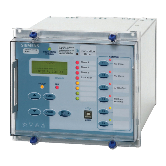
Page 21: Figure 2.5-1 7Sr21 With 3 + 8 Leds In E6 Case
Figure 2.5-2 7SR220 with 3 + 16 LEDs in E8 Case Figure 2.5-3 7SR22 with Function Keys and 3 + 8 LEDs in E8 Case NOTE: Pushbuttons on cover not shown Unrestricted ©2018 Siemens Protection Devices Limited Page 17 of 94... -
Page 22: Figure 2.5-4 7Sr22 With Function Keys & 3 + 8 Leds In E8 Case And Ethernet
This green LED is steadily illuminated to indicate that DC voltage has been applied to the relay power supply and that the relay is operating correctly. If the internal relay watchdog detects an internal fault then this LED will continuously flash. Unrestricted Page 18 of 94 ©2018 Siemens Protection Devices Limited... - Page 23 NOTE: All settings and configuration of LEDs, BI, BO and function keys can be accessed and set by the user using these keys. Alternatively configuration/settings files can be loaded into the relay using ‘Reydisp Evolution’. Unrestricted ©2018 Siemens Protection Devices Limited Page 19 of 94...
- Page 24 Each pushbutton has an associated LED. LEDs can be programmed as hand or self reset and can be illuminated as green, yellow or red (OUTPUT CONFIG > LED CONFIG). Function keys can be used with Quick Logic. Unrestricted Page 20 of 94 ©2018 Siemens Protection Devices Limited...
-
Page 25: Current Inputs
This allows the relay to provide panel indications and alarms. The binary inputs are sampled every 5 ms. Figure 2.8-1 Binary Input Logic Unrestricted ©2018 Siemens Protection Devices Limited Page 21 of 94... -
Page 26: Binary Outputs (Output Relays)
OUTPUT MATRIX (Or gates) OUTPUT OUTPUT CONFIG> CONFIG> BINARY BINARY OUTPUT OUTPUT CONFIG CONFIG BO n Output n Event & & BO n hand reset & Figure 2.9-1 Binary Output Logic Unrestricted Page 22 of 94 ©2018 Siemens Protection Devices Limited... -
Page 27: Virtual Input/Outputs
Restart Count in a given time SYSTEM CONFIG>Unexpected Restart Period, it can be configured using the SYSTEM CONFIG>Unexpected Restart Blocking setting to remove itself from service. In this case the Relay will display a typical error message such as: - Figure 2.11-2 Start-up Counter Meter Unrestricted ©2018 Siemens Protection Devices Limited Page 23 of 94... -
Page 28: Protection Healthy/Defective
An alarm can be provided if the relay is withdrawn from the case. A contact is provided in the case at positions 25-26 of the PSU module, this contact closes when the relay is withdrawn. Unrestricted Page 24 of 94 ©2018 Siemens Protection Devices Limited... -
Page 29: Section 3: Protection Functions
I and I are detected as forward flowing currents and I is detected as reverse current flow, phases L1 and L3 will operate forwards, while phase L2 will be inhibited. Unrestricted ©2018 Siemens Protection Devices Limited Page 25 of 94... -
Page 30: Figure 3.1.1-1 Logic Diagram: Directional Overcurrent Element (67)
This prevents mal-operation under fuse failure/MCB tripped conditions where noise voltages can be present. Figure 3.1.1-1 Logic Diagram: Directional Overcurrent Element (67) Unrestricted Page 26 of 94 ©2018 Siemens Protection Devices Limited... -
Page 31: Instantaneous Overcurrent Protection (50)
(79 P/F Prot’n Trip n = Delayed). 50-n Inrush Action: Inhibit Operation of the inrush current detector function. 50-n VTS Action: Inhibit Operation of the VT Supervision function (7SR22). Figure 3.1.2-1 Logic Diagram: Instantaneous Over-current Element Unrestricted ©2018 Siemens Protection Devices Limited Page 27 of 94... -
Page 32: Time Delayed Overcurrent Protection (51)
Activation of the cold load settings (see section 3.7). 51-n Inrush Action: Inhibit Operation of the inrush current detector function. 51-n VTSAction: Inhibit Operation of the VT Supervision function (7SR22). Unrestricted Page 28 of 94 ©2018 Siemens Protection Devices Limited... -
Page 33: Figure 3.1.3-1 Logic Diagram: Time Delayed Overcurrent Element
L1 Dir En & IL2 Fwd & & IL2 Rev L2 Dir En & IL3 Fwd & & IL3 Rev L3 Dir En Figure 3.1.3-1 Logic Diagram: Time Delayed Overcurrent Element Unrestricted ©2018 Siemens Protection Devices Limited Page 29 of 94... -
Page 34: Current Protection: Voltage Controlled Overcurrent (51V) - 7Sr22
51V Setting 51-n Multiplier < x IL1 51-n Setting < Delayed x IL2 51-n Setting Overcurrent (51-n) < x IL3 51-n Setting Figure 3.2-1 Logic Diagram: Voltage Controlled Overcurrent Protection Unrestricted Page 30 of 94 ©2018 Siemens Protection Devices Limited... -
Page 35: Current Protection: Derived Earth Fault (67N, 51N, 50N)
° ° ° For fault current of -45 (I lagging V by 45 ) a 67 Char Angle of -45 is required for maximum sensitivity. Unrestricted ©2018 Siemens Protection Devices Limited Page 31 of 94... -
Page 36: Instantaneous Derived Earth Fault Protection (50N)
When ‘delayed’ trips only are allowed in the auto-reclose sequence (79 E/F Prot’n Trip n = Delayed). 50N-n VTSAction: Inhibit Operation of the VT Supervision function (7SR22). 50N-n Inrush Action: Inhibit Operation of the current inrush detector function. Unrestricted Page 32 of 94 ©2018 Siemens Protection Devices Limited... -
Page 37: Time Delayed Derived Earth Fault Protection (51N)
A fixed additional operate time can be added to the characteristic using the 51N-n Follower DTL setting. Where directional elements are present the direction of operation can be set using 51N-n Dir. Control setting. Directional logic is provided independently for each 51N-n element. Unrestricted ©2018 Siemens Protection Devices Limited Page 33 of 94... -
Page 38: Figure 3.3.3-1 Logic Diagram: Derived Time Delayed Earth Fault Protection
51N-n Inrush Action: Inhibit Operation of the current inrush detector function. 51N-n VTSAction: Inhibit Operation of the VT Supervision function (7SR22). Figure 3.3.3-1 Logic Diagram: Derived Time Delayed Earth Fault Protection Unrestricted Page 34 of 94 ©2018 Siemens Protection Devices Limited... -
Page 39: Current Protection: Measured Earth Fault (67G, 51G, 50G)
Operation of protection elements set as directional will be inhibited. This prevents mal-operation under fuse failure/MCB tripped conditions where noise voltages can be present. Figure 3.4.1-1 Logic Diagram: Measured Directional Earth Fault Protection Unrestricted ©2018 Siemens Protection Devices Limited Page 35 of 94... -
Page 40: Instantaneous Measured Earth Fault Protection (50G)
(79 E/F Prot’n Trip n = Delayed). 50G-n Inrush Action: Inhibit Operation of the current inrush detector function. 50G-n VTSAction: Inhibit Operation of the VT Supervision function (7SR22). Figure 3.4.2-1 Logic Diagram: Measured Instantaneous Earth-fault Element Unrestricted Page 36 of 94 ©2018 Siemens Protection Devices Limited... -
Page 41: Time Delayed Measured Earth Fault Protection (51G)
51G-n Inrush Action: Inhibit Operation of the inrush current detector function. 51G-n VTSAction: Inhibit Operation of the VT Supervision function (7SR22). Figure 3.4.3-1 Logic Diagram: Measured Time Delayed Earth Fault Element (51G) Unrestricted ©2018 Siemens Protection Devices Limited Page 37 of 94... -
Page 42: Current Protection: Sensitive Earth Fault (67Sef, 51Sef, 50Sef)
Operation of protection elements set as directional will be inhibited. This prevents mal-operation under fuse failure/MCB tripped conditions where noise voltages can be present. Unrestricted Page 38 of 94 ©2018 Siemens Protection Devices Limited... -
Page 43: Instantaneous Sensitive Earth Fault Protection (50Sef)
67SEF Wattmetric Power setting for any SEF element operation. The residual power P equal to the wattmetric component of 3V and therefore the wattmetric component of 9V Unrestricted ©2018 Siemens Protection Devices Limited Page 39 of 94... -
Page 44: Figure 3.5.2-1 Logic Diagram: 50 Sef Instantaneous Element
7SR210 & 7SR220 Description of Operation Figure 3.5.2-1 Logic Diagram: 50 SEF Instantaneous Element Figure 3.5.2-2 Logic Diagram: 50 SEF Instantaneous Element Compensated Networks Unrestricted Page 40 of 94 ©2018 Siemens Protection Devices Limited... -
Page 45: Time Delayed Sensitive Earth Fault Protection (51Sef)
Forward/Reverse operating range. If 67SEF Wattmetric is set to Enabled, the calculated residual real power must be above the 67SEF Wattmetric Power setting. The residual power P is equal to the wattmetric component of 3V and therefore the wattmetric component of 9V Unrestricted ©2018 Siemens Protection Devices Limited Page 41 of 94... -
Page 46: Figure 3.5.3-1 Logic Diagram: 51 Sef Time Delayed Element
7SR210 & 7SR220 Description of Operation Figure 3.5.3-1 Logic Diagram: 51 SEF Time Delayed Element Figure 3.5.3-2 Logic Diagram: 51 SEF Time Delayed Element Compensated Networks Unrestricted Page 42 of 94 ©2018 Siemens Protection Devices Limited... -
Page 47: Current Protection: High Impedance Restricted Earth Fault (64H)
Operation of the high impedance element can be inhibited from: - Inhibit 64H A binary or virtual input, function key or remote data Comms Figure 3.6-1 Logic Diagram: High Impedance REF (64H) Unrestricted ©2018 Siemens Protection Devices Limited Page 43 of 94... -
Page 48: Current Protection: Cold Load (51C)
Resetting the timer for each trip could result in damaging levels of current flowing for a prolonged period during a rapid sequence of trips/closes. Cold load trips use the same binary output(s) as the associated 51-n element. Figure 3.7-1 Logic Diagram: Cold Load Settings (51c) Unrestricted Page 44 of 94 ©2018 Siemens Protection Devices Limited... -
Page 49: Current Protection: Negative Phase Sequence Overcurrent (46Nps)
A binary or virtual input, function key or remote data Comms Inhibit 46DT A binary or virtual input, function key or remote data Comms Figure 3.8-1 Logic Diagram: Negative Phase Sequence Overcurrent (46NPS) Unrestricted ©2018 Siemens Protection Devices Limited Page 45 of 94... -
Page 50: Current Protection: Under-Current (37, 37G & 37Sef)
Figure 3.9-1 Logic Diagram: Undercurrent Detector (37, 37G & 37SEF) 3.10 Current Protection: Under-Current Guarded (37) A level detector 37-n U/I Guard Setting sets the pick-up current. Figure 3.10-1 Logic Diagram: Undercurrent Guarded Detector (37) Unrestricted Page 46 of 94 ©2018 Siemens Protection Devices Limited... -
Page 51: Current Protection: Thermal Overload (49)
The thermal state may be reset from the fascia or externally via a binary input. Thermal overload protection can be inhibited from: - Inhibit 49 A binary or virtual input, function key or remote data Comms. Unrestricted ©2018 Siemens Protection Devices Limited Page 47 of 94... -
Page 52: Figure 3.11-1 Logic Diagram: Thermal Overload Protection (49S)
7SR210 & 7SR220 Description of Operation Figure 3.11-1 Logic Diagram: Thermal Overload Protection (49S) Unrestricted Page 48 of 94 ©2018 Siemens Protection Devices Limited... -
Page 53: Current Protection: Arc Flash Detector (50 Afd)
& AFD Zone 6 AFD Zone 6 Flash 50AFD Setting 50 AFD 50 AFD PhA 50 AFD PhB 50 AFD PhC Figure 3.12-1 Logic Diagram: Arc Flash Detector (50 AFD) Unrestricted ©2018 Siemens Protection Devices Limited Page 49 of 94... -
Page 54: Voltage Protection: Phase Under/Over Voltage (27/59) - 7Sr22
A binary or virtual input, function key or remote data Comms. 27/59-n VTSInhibit: Yes Operation of the VT Supervision function. 27/59-n U/V Guarded Under voltage guard element. Figure 3.13-1 Logic Diagram: Under/Over Voltage Elements (27/59) Unrestricted Page 50 of 94 ©2018 Siemens Protection Devices Limited... -
Page 55: Voltage Protection: Negative Phase Sequence Overvoltage (47) - 7Sr22
Operation of the negative phase sequence voltage elements can be inhibited from: - Inhibit 47-n A binary or virtual input, function key or remote data Comms. Figure 3.14-1 Logic Diagram: NPS Overvoltage Protection (47) Unrestricted ©2018 Siemens Protection Devices Limited Page 51 of 94... -
Page 56: Voltage Protection: Neutral Overvoltage (59N) - 7Sr22
5-limb VT or 3 single phase VTs. The VT primary winding neutral must be earthed to allow the flow of zero sequence current. Figure 3.15-1 Logic Diagram: Neutral Overvoltage Element Unrestricted Page 52 of 94 ©2018 Siemens Protection Devices Limited... -
Page 57: Voltage Protection: Under/Over Frequency (81) - 7Sr22
81-n Operation Setting 81-n Setting < General Pickup & 81-n Hysteresis < General Pickup < 81-n Delay Voltage > < 81-n Selection 81-n Figure 3.16-1 Logic Diagram: Under/Over Frequency Detector (81) Unrestricted ©2018 Siemens Protection Devices Limited Page 53 of 94... -
Page 58: Power Protection: Power (32) - 7Sr22
Gn32: Setting Gn 32-n U/C Guard Setting & < & < & < Gn 32-n Delay -VAr -VAr 32-n +VAr +VAr General Pickup Figure 3.17-1 Logic Diagram: Power Protection (32) Unrestricted Page 54 of 94 ©2018 Siemens Protection Devices Limited... -
Page 59: Power Protection: Sensitive Power (32S) - 7Sr22
Gn 32S-n U/C & Guard Setting & < 32S CT Angle Comp Gn 32S-n Delay -VAr -VAr 32S-n +VAr +VAr General Pickup Figure 3.18-1 Logic Diagram: Sensitive Power Protection (32S) Unrestricted ©2018 Siemens Protection Devices Limited Page 55 of 94... -
Page 60: Power Protection: Power Factor (55) - 7Sr22
The measured current is below the Gn 55 U/C Guard setting A VT Fail condition is detected Inhibit 55-n A binary or virtual input. Figure 3.19-1 Logic Diagram: Power Factor Protection (55) Unrestricted Page 56 of 94 ©2018 Siemens Protection Devices Limited... -
Page 61: Section 4: Control & Logic Functions
Successful Close output issued. A single, common Reclaim time is used (Reclaim Timer). When an auto-reclose sequence does not result in a successful reclosure the relay goes to the lockout state. Unrestricted ©2018 Siemens Protection Devices Limited Page 57 of 94... - Page 62 79 In Progress 79 AR Close CB 79 Successful AR 79 Lockout 79 Close Onto Fault 79 CB Fail to Close 79 Trip _Reclose 79 Trip _Lockout 79 Block Extern Unrestricted Page 58 of 94 ©2018 Siemens Protection Devices Limited...
-
Page 63: Auto Reclose Sequences
The CB close output relay is energised after the dead time has elapsed. Trip (Inst) Trip (Inst) Trip (Inst) Trip (Delayed) Dead Time Dead Time Dead Time Dead Time Figure 4.1.2-1 Typical Sequence with 3 Instantaneous and 1 Delayed trip Unrestricted ©2018 Siemens Protection Devices Limited Page 59 of 94... -
Page 64: Autoreclose Prot'n Menu
This is repeated as long as the fault is being cleared by the downstream device such that the Relay moves through the sequence bypassing the INST Trips and moving on to the Delayed Trip to maintain Grading margins. Unrestricted Page 60 of 94 ©2018 Siemens Protection Devices Limited... - Page 65 The Lockout condition has a delayed drop-off time of 2s. The Lockout condition cannot be reset if there is an active lockout input. Note: If the ‘CB Total Trip Count’ or the ‘CB Frequent Ops Count’ target is reached the relay will do one delayed tip and lockout. Unrestricted ©2018 Siemens Protection Devices Limited Page 61 of 94...
-
Page 66: P/F Shots Sub-Menu
As above but E/F settings. SEF Shots Sub-Menu This menu allows the Sensitive Earth trip/reclose sequence to be parameterized:- As above but SEF Settings, Note: - SEF does not have HighSets Unrestricted Page 62 of 94 ©2018 Siemens Protection Devices Limited... -
Page 67: Extern Shots Sub-Menu
External AutoReclose sequence can be applied for this purpose. By setting-up internal Quick Logic equation(s) the user can define and set what should occur when any one of these other elements operates. Unrestricted ©2018 Siemens Protection Devices Limited Page 63 of 94... -
Page 68: Figure 4.7-1 Basic Auto-Reclose Sequence Diagram
7SR210 & 7SR220 Description of Operation Figure 4.7-1 Basic Auto-Reclose Sequence Diagram Unrestricted Page 64 of 94 ©2018 Siemens Protection Devices Limited... -
Page 69: Manual Control
Reset operation can be useful, however, as it allows a close or trip sequence to be aborted by dropping off the binary input signal. Unrestricted ©2018 Siemens Protection Devices Limited Page 65 of 94... -
Page 70: Synchronising
The voltage is compared to the corresponding voltage from the three-phase arrangement on the other side of the circuit-breaker. Voltage settings are set as a percentage of the nominal voltage specified in the CT/VT Config menu. Unrestricted Page 66 of 94 ©2018 Siemens Protection Devices Limited... -
Page 71: Figure 4.9.3-1 Voltage Detector Operation
Differential voltage detectors The differential voltage detector, if enabled, can block a close output command if the difference between the line and bus voltages is greater than the differential voltage setting value. Unrestricted ©2018 Siemens Protection Devices Limited Page 67 of 94... -
Page 72: Check Synchronising Mode
Phase Within Range ? Slip Timer & CheckSync Phase Angle Setting Close & Line U/V Block Slip Timer Block Setting Bus U/V Block BLock V Block Block Figure 4.9.4-1 Check Sync Function Unrestricted Page 68 of 94 ©2018 Siemens Protection Devices Limited... -
Page 73: System Split Detector
Synchronising mode. The reversion allows the device to use the wider Check Sync parameters, to allow a close following the restoration of normal operation when the islanded network has been reconnected to the main network by successful reclosure of a parallel connection. Unrestricted ©2018 Siemens Protection Devices Limited Page 69 of 94... -
Page 74: System Synchronising Mode
The slip frequency must be less than the 25 COZ Slip Freq but greater than the 25 Split Slip setting to avoid reversion to Check Synchronising conditions. Since this feature is part of the System Synchronising function, 25 System Sync must also be set to Enabled. Unrestricted Page 70 of 94 ©2018 Siemens Protection Devices Limited... -
Page 75: Live/Dead Indication
RMS algorithm and always pass through the dead zone first. A wide range is provided for live and dead voltage detector levels but the live and dead zones must not overlap. Unrestricted ©2018 Siemens Protection Devices Limited Page 71 of 94... -
Page 76: Circuit Breaker
Where a protection pickup is raised during the reclaim time the relay advances to the next part of the reclose sequence. The relay goes to the Lockout state if the CB is open at the end of the reclaim time or a protection operates during the final reclaim time. Unrestricted Page 72 of 94 ©2018 Siemens Protection Devices Limited... -
Page 77: Figure 4.11-1 Logic Diagram: Circuit Breaker Status
An instantaneous CB Alarm is given for a 1/1 state – i.e. where the CB indicates it is both Open and Closed at the same time. Figure 4.11-1 Logic Diagram: Circuit Breaker Status Unrestricted ©2018 Siemens Protection Devices Limited Page 73 of 94... - Page 78 Hot Line can be configured to be switched In/Out by binary inputs, function keys or by commands via the communications protocols. There are no other configurable options for Hot Line. Unrestricted Page 74 of 94 ©2018 Siemens Protection Devices Limited...
-
Page 79: Quick Logic
En Counter Reset Mode = Multi Shot: The En Counter Reset Time is started each time the counter is incremented. Where En Counter Reset Time elapses without further count increments the count value is reset to zero. Unrestricted ©2018 Siemens Protection Devices Limited Page 75 of 94... -
Page 80: Figure 4.12-1Sequence Diagram: Quick Logic Pu/Do Timers (Counter Reset Mode Off)
(O), LED (L) or Virtual Input/Output (V) combination. Protection functions can be used in Quick Logic by mapping them to a Virtual Input / Output. Refer to Applications Guide for examples of Logic schemes. Unrestricted Page 76 of 94 ©2018 Siemens Protection Devices Limited... -
Page 81: Section 5: Supervision Functions
Operation of the CB Fail elements can be inhibited from: - Inhibit 50BF A binary input, virtual input or remote data Comms. Figure 5.1-1 Logic Diagram: Circuit Breaker Fail Protection (50BF) Unrestricted ©2018 Siemens Protection Devices Limited Page 77 of 94... -
Page 82: Vt Supervision (60Vts) - 7Sr22
Ext Reset 60VTS A binary or virtual input, or function key and a VT failure condition no longer exists. Inhibit 60VTS A binary, virtual input, function key or remote data Comms. Unrestricted Page 78 of 94 ©2018 Siemens Protection Devices Limited... -
Page 83: Busbar Vt Fail (60Vtf-Bus) - 7Sr22
A similar setting is available, 79 LO Line VT Fail, which when Enabled will provide a Lockout for a Line VT failure detected by the 60VTS function. Unrestricted ©2018 Siemens Protection Devices Limited Page 79 of 94... -
Page 84: Ct Supervision (60Cts & 60Cts-I)
60CTS Pick-Up Inhibit 60CTS 60CTS Delay 60CTS Operated & 60CTS Operated 60CTS Vnps Filter < & 60CTS Inps Filter > Figure 5.4.2-1 Logic Diagram: CT Supervision Function (60CTS) – 7SR22 Unrestricted Page 80 of 94 ©2018 Siemens Protection Devices Limited... -
Page 85: Broken Conductor (46Bc)
The use of one or two binary inputs mapped to the same Trip Circuit Supervision element (e.g. 74TCS-n) allows the user to realise several alternative monitoring schemes – see ‘Applications Guide’. Figure 5.6-1 Logic Diagram: Trip Circuit Supervision Feature (74TCS) Unrestricted ©2018 Siemens Protection Devices Limited Page 81 of 94... -
Page 86: Inrush Restraint (81Hbl2)
All phases are inhibited when any phase detects an inrush condition. An output is given where the measured value of the second harmonic component is above the 81HBL2 setting. Figure 5.7-1 Logic Diagram: Harmonic Block Feature (81HBL2) Unrestricted Page 82 of 94 ©2018 Siemens Protection Devices Limited... -
Page 87: Over Fluxing Detector (81Hlb5)
All phases are inhibited when any phase detects an inrush condition An output is given where the measured fifth harmonic component content is above the 81HBL5 setting. Figure 5.8-1 Logic Diagram: Over Fluxing Detector (81HLB5) Unrestricted ©2018 Siemens Protection Devices Limited Page 83 of 94... -
Page 88: Load Blinder (21)
Zpps is calculated from Vpps and Ipps. The magnitude and angle of Zpps is compared with 21LB-3P Impedance and 21LB-3P Angle to determine if the impedance is in operate or block and/or FWD or REV zone. Figure 5.9.1-1 Logic Diagram: Load Blinder Three-Phase Unrestricted Page 84 of 94 ©2018 Siemens Protection Devices Limited... -
Page 89: Load Blinder (21) Single-Phase
Blinders are used to block overcurrent operation for loads above a particular level and angle. A Blinder is an impedance sensing element with a straight-line characteristic when plotted on the R – X plane Figure 5.9.2-1 Logic Diagram: Load Blinder Single-Phase Unrestricted ©2018 Siemens Protection Devices Limited Page 85 of 94... -
Page 90: Figure 5.9.2-2 Load Blinder And Angle
= 21LB-3P Impedance setting Point 10 Point 3 b = 21LB-3P Angle +ve Point 9 Point 4 setting c = 21LB-3P Angle -ve setting Figure 5.9.2-2 Load Blinder and Angle Unrestricted Page 86 of 94 ©2018 Siemens Protection Devices Limited... -
Page 91: Section 6: Other Features
Block will only increment for protection trip commands. CB Frequent Ops Count Logs the number of trip operations in a rolling window period of one hour. An output is available to reset this counter. Unrestricted ©2018 Siemens Protection Devices Limited Page 87 of 94... -
Page 92: I 2 T Cb Wear
Binary Inputs or LED’s already assigned to that function. Any protection function which is enabled in the setting menu will appear in the Output Matrix Test. Unrestricted Page 88 of 94 ©2018 Siemens Protection Devices Limited... -
Page 93: Data Storage
- waveform 10 – to be overwritten. Stored waveforms can be deleted from the relay fascia using the DATA STORAGE > Clear Waveforms setting or via Reydisp. Unrestricted ©2018 Siemens Protection Devices Limited Page 89 of 94... -
Page 94: Fault Records
(where fitted) analogue signal are recorded and stored at a user defined rate e.g. 35 days @ 5 minute intervals and > 1 year @ 1 hour intervals. Unrestricted Page 90 of 94 ©2018 Siemens Protection Devices Limited... -
Page 95: Energy Storage
The value is stored in the range 0-999999 which continues from zero automatically when 999999 is reached. Unrestricted ©2018 Siemens Protection Devices Limited Page 91 of 94... -
Page 96: Fault Locator
The user can add the meters that are most commonly viewed to a ‘Favourites’ window by pressing the ‘ENTER’ key when viewing a meter. The relay will scroll through these meters at an interval set in the System Config/Favourite Meters Timer menu. Unrestricted Page 92 of 94 ©2018 Siemens Protection Devices Limited... -
Page 97: Operating Mode
The default date is set at 01/01/2000 deliberately to indicate the date has not yet been set. When editing the Time, only the hours and minutes can be edited. When the user presses ENTER after editing the seconds are zeroed and the clock begins running. Unrestricted ©2018 Siemens Protection Devices Limited Page 93 of 94... -
Page 98: Time Synchronisation - Data Communication Interface
The password validation screen also displays a numerical code. If the password is lost or forgotten, this code should be communicated to Siemens Protection Devices Ltd. and the password can be retrieved. Unrestricted Page 94 of 94 ©2018 Siemens Protection Devices Limited... -
Page 99: The Copyright And Other Intellectual Property Rights In This Document, And In Any Model Or Article Produced From It
Protection Devices Limited. No part of this document shall be reproduced or modified or stored in another form, in any data retrieval system, without the permission of Siemens Protection Devices Limited, nor shall any model or article be reproduced from this document unless Siemens Protection Devices Limited consent. - Page 100 2435H85009R8b-7f (7SR220) Added 32 Directional Power, 32S Sensitive Power, 55 Power 2017/08 2435H85008R8e-8a (7SR210) Factor, 81HLB5 Overfluxing, 67SEF Compensated Network, 2435H85009R8e-8a (7SR220) 67SEF Wattmetric. Increased I/O. Event Data on LCD. Unrestricted Page 2 of 14 © 2018 Siemens Protection Devices Limited...
- Page 101 Figure 2.1.5-1 Additional (Optional) rear RS232 + IRG-B connection to a PC ............. 11 Figure 2.1.6-1 EN100 Ethernet Module ......................12 Figure 2.1.8-1 PC Comm Port Selection ......................14 Unrestricted © 2018 Siemens Protection Devices Limited Page 3 of 1...
-
Page 102: Relay Menus And Display
To change the contrast on the LCD insert a flat nosed screwdriver into the screwhead below the contrast symbol, turning the screwhead left or right decreases and increases the contrast of the LCD. Figure 1.1-2 Fascia Contrast symbol Unrestricted Page 4 of 14 © 2018 Siemens Protection Devices Limited... - Page 103 7SR210 & 7SR220 Configuration Guide Figure 1.1-3 Relay Fascia (Please note fascia may differ from illustration) Unrestricted © 2018 Siemens Protection Devices Limited Page 5 of 1...
-
Page 104: User Interface Operation
LEDs will momentarily light up to indicate their correct operation. It is also moves the cursor right ► when navigating through menus and settings. Unrestricted Page 6 of 14 © 2018 Siemens Protection Devices Limited... - Page 105 BINARY OUTPUT CONFIG LED CONFIG PICKUP CONFIG MAINTENANCE CB COUNTERS I^2T CB WEAR DATA STORAGE DEMAND/DATA LOG WAVEFORM STORAGE FAULT STORAGE COMMUNICATIONS Figure 1.2.1-2 Typical Menu Structure for 7SR21 relay Unrestricted © 2018 Siemens Protection Devices Limited Page 7 of 1...
- Page 106 OUTPUT CONFIG OUTPUT MATRIX BINARY OUTPUT CONFIG LED CONFIG PICKUP CONFIG CB MAINTENANCE CB COUNTERS I^2T CB WEAR DATA STORAGE COMMUNICATIONS Figure 1.2.1-3 Typical Menu Structure for 7SR22 relay Unrestricted Page 8 of 14 © 2018 Siemens Protection Devices Limited...
-
Page 107: Section 2: Configuring The Relay Using Reydisp Evolution
Interface cable and converters are required depending which port is being used. 2.1.1 RONT CONNECTION To connect your pc locally via the front USB port. Figure 2.1.1-1 USB connection to a PC Unrestricted © 2018 Siemens Protection Devices Limited Page 9 of 1... -
Page 108: Standard Rear Rs485 Connection
Sigma devices have a 25 pin female D connector with the following pin out. Function Transmit Data Received Data Request to Send Clear to Send Data set ready Signal Ground Received Line Signal Detector Data Terminal Ready Unrestricted Page 10 of 14 © 2018 Siemens Protection Devices Limited... -
Page 109: Optional Rear Rs485 + Irig-B Connection
Carrier Direct (CD) Receive Data (RXD) Transmit Data (TXD) Data Terminal Ready (DTR) Signal Ground (GND) Data set ready (DSR) Request to send (RTS) Clear to Send (CTS) Ring Indicator (RI) Unrestricted © 2018 Siemens Protection Devices Limited Page 11 of... -
Page 110: Optional Rear En100 Ethernet Module
COM1 – Standard RS485 Rear Port COM2 - USB Port COM3 – Optional Fibre Optic, RS485, RS232 or Ethernet Port COM4 – Additional (Optional) Rear Connection** LAN – Optional Ethernet Ports Unrestricted Page 12 of 14 © 2018 Siemens Protection Devices Limited... - Page 111 Setting is only visible when Secon DNP3 Application 5, 6 ... 299, 300 a port Protocol is set to Timeout DNP3 *Not applicable for RS485 or RS232 interface modules. **Fibre Optic Module only Unrestricted © 2018 Siemens Protection Devices Limited Page 13 of...
- Page 112 Relay > Set Address > Device Map. The relay can now be configured using the Reydisp Evolution software. Please refer to the Reydisp Evolution Manual for further guidance. Unrestricted Page 14 of 14 © 2018 Siemens Protection Devices Limited...
-
Page 113: The Copyright And Other Intellectual Property Rights In This Document, And In Any Model Or Article Produced From It
Protection Devices Limited. No part of this document shall be reproduced or modified or stored in another form, in any data retrieval system, without the permission of Siemens Protection Devices Limited, nor shall any model or article be reproduced from this document unless Siemens Protection Devices Limited consent. - Page 114 Additional communications data control features, meters. Added Arc Flash Detector. Over current TM Setting Range 2015/06 2435H85008R8a-7f (7SR210) extended. 2016/02 2435H85008R8b-7f (7SR210) EN100+ Compatibility. 2435H85008R8e-8a (7SR210) Event Data on LCD. 2017/08 Unrestricted Page 2 of 12 © 2018 Siemens Protection Devices Limited...
- Page 115 1.8. Binary Input Meters ................10 1.9. Binary Output Meters ................11 1.10. Virtual Meters ..................11 1.11. Communication Meters ................ 11 1.12. Miscellaneous Meters ................12 1.13. Quick Logic Meters ................12 Unrestricted ©2018 Siemens Protection Devices Limited Page 3 of 12...
- Page 116 7SR210 Instrumentation Guide 1.Function Diagram Unrestricted Page 4 of 12 © 2018 Siemens Protection Devices Limited...
- Page 117 7SR210 Instrumentation Guide 2.Menu Structure Unrestricted ©2018 Siemens Protection Devices Limited Page 5 of 12...
- Page 118 0.00xIn ---- angles with respect to PPS current. Ipps 0.00xIn ---- Inps 0.00xIn ---- Harmonic Current Displays the 3 phase currents 2 Harmonic components Nominal RMS values. 0.00xIn 0.00xIn 0.00xIn Unrestricted Page 6 of 12 © 2018 Siemens Protection Devices Limited...
- Page 119 Harmonic components Nominal RMS values. 0.00xIn 0.00xIn 0.00xIn Last Trip P/F Displays the Last Trip Fault Current.. 0.00A 0.00A 0.00A Last Trip E/F Displays the Last Trip Fault Current.. 0.00A 0.00A Unrestricted ©2018 Siemens Protection Devices Limited Page 7 of 12...
- Page 120 Displays the number of CB Phase E/F Trips experienced by the CB Count Target CB Delta Trips Displays the number of CB trips experienced by the CB Count Target Unrestricted Page 8 of 12 © 2018 Siemens Protection Devices Limited...
- Page 121 I Phase B Demand Shows the Max, Min and Mean for Phase B. 0.00A 0.00A Mean 0.00A I Phase C Demand Shows the Max, Min and Mean for Phase C. Unrestricted ©2018 Siemens Protection Devices Limited Page 9 of 12...
- Page 122 Displays the state of DC binary inputs 1 to 39 (The number of binary inputs may BI 9-16 ----.---- vary depending on model) BI 17-24 ----.---- BI 25-32 ----.---- BI 33-39 ----.--- Unrestricted Page 10 of 12 © 2018 Siemens Protection Devices Limited...
- Page 123 Displays traffic on Com1 Rx1 Errors COM2 TRAFFIC Displays traffic on Com2 Rx2 Errors COM3 TRAFFIC Displays traffic on Com3 Rx3 Errors COM4 TRAFFIC Displays traffic on Com4 Rx4 Errors Unrestricted ©2018 Siemens Protection Devices Limited Page 11 of 12...
- Page 124 Shows the state of an individual equation. EQN shows the equation state. TMR shows the timer progress and state for the equation. CNT shows the count progress and state for the equation. Unrestricted Page 12 of 12 © 2018 Siemens Protection Devices Limited...
-
Page 125: The Copyright And Other Intellectual Property Rights In This Document, And In Any Model Or Article Produced From It
Protection Devices Limited. No part of this document shall be reproduced or modified or stored in another form, in any data retrieval system, without the permission of Siemens Protection Devices Limited, nor shall any model or article be reproduced from this document unless Siemens Protection Devices Limited consent. - Page 126 2435H85008R8a-7f (7SR210) extended. 2016/02 EN100+ Compatibility. 2435H85008R8b-7f (7SR210) 2435H85009R8b-7f (7SR220) Added 32 Directional Power, 32S Sensitive Power, 55 Power 2017/08 2435H85008R8e-8a (7SR210) Factor, 81HLB5 Overfluxing. Increased I/O. 2435H85009R8e-8a (7SR220) Unrestricted Page 2 of 61 © 2018 Siemens Protection Devices Limited...
- Page 127 3.4.8.3. 37G-1 ................18 3.4.8.4. 37G-2 ................18 3.4.9. Thermal ..................19 3.4.10. ARC Flash Detector ............. 19 3.5. Supervision ..................19 3.5.1. CB Fail ..................19 3.5.2. CT Supervision ................. 19 Unrestricted ©2018 Siemens Protection Devices Limited Page 3 of 61...
- Page 128 3.10. Data Storage ..................58 3.10.1. Demand Data/Log ..............58 3.10.2. Waveform Storage ............... 59 3.10.3. Fault Storage ............... 59 3.10.4. Event Storage ..............59 3.10.5. Communications ..............60 Unrestricted Page 4 of 61 © 2018 Siemens Protection Devices Limited...
- Page 129 7SR210 Settings Guide 1.Function Diagram Unrestricted ©2018 Siemens Protection Devices Limited Page 5 of 61...
-
Page 130: Menu Structure
7SR210 Settings Guide 2.Menu Structure Unrestricted Page 6 of 61 © 2018 Siemens Protection Devices Limited... -
Page 131: Relay Settings
Trip Alert Screen, the only way to leave this screen is by acknowledging the trip through the TEST/RESET button on the relay fascia General Alarm Alert Disabled, Enabled Enabled Unrestricted ©2018 Siemens Protection Devices Limited Page 7 of 61... -
Page 132: Function Config
When set to Disabled, no NPS Overcurrent elements will be functional and all associated settings will be hidden. (The Setting Dependencies setting being set to Disabled will make all settings visible but will not allow them to operate). Unrestricted Page 8 of 61 © 2018 Siemens Protection Devices Limited... - Page 133 When set to Disabled, no Arc Flash Detector elements will be functional and all associated settings will be hidden. (The Setting Dependencies setting being set to Disabled will make all settings visible but will not allow them to operate). Unrestricted ©2018 Siemens Protection Devices Limited Page 9 of 61...
-
Page 134: Current Protection
Gn 51-2 Min Operate Time 0, 0.01 ... 19.99, 20 Minimum operate time of element. Gn 51-2 Follower DTL 0, 0.01 ... 19.99, 20 Additional definite time added after characteristic time Unrestricted Page 10 of 61 © 2018 Siemens Protection Devices Limited... -
Page 135: Cold Load
1 xIn 51-1 element parameter used when Cold Load operates Gn 51c-1 Char DTL, IEC-NI, IEC-VI, IEC-EI, IEC-LTI, IEC-NI ANSI-MI, ANSI-VI, ANSI-EI 51-1 element parameter used when Cold Load operates Unrestricted ©2018 Siemens Protection Devices Limited Page 11 of 61... - Page 136 0, 0.01 ... 19.99, 20 Additional definite time added after characteristic time Gn 51N-1 Reset (ANSI) Decaying, 0 ... 59, 60 Selects between an ANSI decaying reset characteristic or a definite time reset Unrestricted Page 12 of 61 © 2018 Siemens Protection Devices Limited...
- Page 137 0, 0.01 ... 14300, 14400 Sets operate delay time Gn 50N-2 Inrush Action Off, Inhibit Selects if the 50N-2 element is blocked from operating when 2nd Harmonic Inrush Detector operates Unrestricted ©2018 Siemens Protection Devices Limited Page 13 of 61...
- Page 138 0, 0.01 ... 19.99, 20 Additional definite time added after characteristic time Gn 51G-2 Reset (ANSI) Decaying, 0 ... 59, 60 Selects between an ANSI decaying reset characteristic or DTL reset Unrestricted Page 14 of 61 © 2018 Siemens Protection Devices Limited...
-
Page 139: Sensitive E/F
Gn 51SEF-1 Min Operate Time 0, 0.01 ... 19.99, 20 Minimum operate time of element. Gn 51SEF-1 Follower DTL 0, 0.01 ... 19.99, 20 Additional definite time added after characteristic time Unrestricted ©2018 Siemens Protection Devices Limited Page 15 of 61... -
Page 140: 51Sef-2
Selects whether the DTL measured Earth fault element is enabled Gn 50SEF-2 Setting 0.005, 0.006 ... 4.995, 5 0.2 xIn Pickup level Gn 50SEF-2 Delay 0, 0.01 ... 14300, 14400 Sets operate delay time Unrestricted Page 16 of 61 © 2018 Siemens Protection Devices Limited... -
Page 141: Restricted E/F
Gn 46DT Setting 0.05, 0.06 ... 3.99, 4 0.1 xIn Pickup level Gn 46DT Delay 0, 0.01 ... 14300, 14400 0.02 s Sets operate delay time Unrestricted ©2018 Siemens Protection Devices Limited Page 17 of 61... -
Page 142: Under Current
3.4.8.4. 37G-2 Description Range Default Gn 37G-2 Element Disabled, Enabled Disabled Gn 37G-2 Setting 0.005, 0.006 ... 4.995, 5 0.2 xIn Gn 37G-2 Delay 0, 0.01 ... 14300, 14400 Unrestricted Page 18 of 61 © 2018 Siemens Protection Devices Limited... -
Page 143: Thermal
CT Supervision Description Range Default Gn 60CTS-I Element Disabled, Enabled Disabled Gn 60CTS-I Setting 0.05, 0.1 ... 1.95, 2 0.05 xIn Gn 60CTS-I Delay 0.03, 0.04 ... 14300, 14400 10 s Unrestricted ©2018 Siemens Protection Devices Limited Page 19 of 61... -
Page 144: Broken Conductor
Disabled, Enabled Disabled Selects whether the trip circuit supervision element 74CCS-3 is enabled Gn 74CCS-3 Delay 0, 0.02 ... 59.98, 60 0.4 s Time delay before trip circuit supervision operates Unrestricted Page 20 of 61 © 2018 Siemens Protection Devices Limited... -
Page 145: Inrush Detector
Gn 79 E/F HS Trips Combination of ( 50N-1, 50N-2, ---- 50G-1, 50G-2 ) Selects which earth fault elements are classed as High Set elements, any selected elements operating will start an autoreclose sequence. Unrestricted ©2018 Siemens Protection Devices Limited Page 21 of 61... -
Page 146: Autoreclose Config
(Fast) or Delayed. When set to Delayed all P/F Inst Trips will be Inhibited for this shot. Gn 79 P/F Deadtime 3 0, 0.1 ... 14300, 14400 Time period between the fault being cleared and the close pulse being issued Unrestricted Page 22 of 61 © 2018 Siemens Protection Devices Limited... -
Page 147: E/F Shots
Selects how many High Set trips are allowed before going to Lockout Gn 79 E/F Delayed Trips To Lockout 1, 2, 3, 4, 5 Selects how many Delayed trips are allowed before going to Lockout Unrestricted ©2018 Siemens Protection Devices Limited Page 23 of 61... -
Page 148: Sef Shots
Inst, Delayed Inst Selects whether a sensitive earth fault line check trip is Instantaneous or Delayed. When set to Delayed all SEF Inst Trips will be Inhibited for this shot. Unrestricted Page 24 of 61 © 2018 Siemens Protection Devices Limited... -
Page 149: Circuit Breaker
Open and Close condition indication. 3.6.5. QUICK LOGIC Description Range Default Quick Logic Disabled, Enabled Disabled Enable or Disable all logic equations E1 Equation Disabled, Enabled Disabled Enable or Disable logic equation E1 Unrestricted ©2018 Siemens Protection Devices Limited Page 25 of 61... - Page 150 = LED numberO(Followed by a digit) = output relay numberV(Followed by a digit) =Virtual Input/Output number.ExamplesMake a function key LED toggle when function key is pressed (requires E1 to drive L11 in output matrix)E1 = F3^L11 Unrestricted Page 26 of 61 © 2018 Siemens Protection Devices Limited...
- Page 151 0, 0.01 ... 14300, 14400 Time before equation output resets, after equation nolonger satisfied E5 Counter Target 1, 2 ... 998, 999 Select number of times equation must be satisfied before equation output operates Unrestricted ©2018 Siemens Protection Devices Limited Page 27 of 61...
- Page 152 Select type of counter reset mode E7 Counter Reset Time 0, 0.01 ... 14300, 14400 Select counter reset time E8 Equation Disabled, Enabled Disabled Enable or Disable logic equation E8 Unrestricted Page 28 of 61 © 2018 Siemens Protection Devices Limited...
- Page 153 = LED numberO(Followed by a digit) = output relay numberV(Followed by a digit) =Virtual Input/Output number.ExamplesMake a function key LED toggle when function key is pressed (requires E1 to drive L11 in output matrix)E1 = F3^L11 Unrestricted ©2018 Siemens Protection Devices Limited Page 29 of 61...
- Page 154 Time before equation output resets, after equation nolonger satisfied E12 Counter Target 1, 2 ... 998, 999 Select number of times equation must be satisfied before equation output operates Unrestricted Page 30 of 61 © 2018 Siemens Protection Devices Limited...
- Page 155 Select type of counter reset mode E14 Counter Reset Time 0, 0.01 ... 14300, 14400 Select counter reset time E15 Equation Disabled, Enabled Disabled Enable or Disable logic equation E15 Unrestricted ©2018 Siemens Protection Devices Limited Page 31 of 61...
- Page 156 Select number of times equation must be satisfied before equation output operates E16 Counter Reset Mode Off, Multi-shot, Single-shot Select type of counter reset mode E16 Counter Reset Time 0, 0.01 ... 14300, 14400 Select counter reset time Unrestricted Page 32 of 61 © 2018 Siemens Protection Devices Limited...
-
Page 157: Input Config
---------------------- BI5, BI6, BI7, BI8, BI9, V1, V2, V3, Selects which inputs inhibit the 51SEF-1 element V4, V5, V6, V7, V8, V9, V10, V11, V12, V13, V14, V15, V16 ) Unrestricted ©2018 Siemens Protection Devices Limited Page 33 of 61... - Page 158 Combination of ( BI1, BI2, BI3, BI4, ---------------------- BI5, BI6, BI7, BI8, BI9, V1, V2, V3, As Above V4, V5, V6, V7, V8, V9, V10, V11, V12, V13, V14, V15, V16 ) Unrestricted Page 34 of 61 © 2018 Siemens Protection Devices Limited...
- Page 159 BI5, BI6, BI7, BI8, BI9, V1, V2, V3, Selects which inputs will reset the CB trip time alarm V4, V5, V6, V7, V8, V9, V10, V11, V12, V13, V14, V15, V16 ) Unrestricted ©2018 Siemens Protection Devices Limited Page 35 of 61...
- Page 160 BI5, BI6, BI7, BI8, BI9, V1, V2, V3, Selects which inputs will issue a close to the circuit breaker. V4, V5, V6, V7, V8, V9, V10, V11, V12, V13, V14, V15, V16 ) Unrestricted Page 36 of 61 © 2018 Siemens Protection Devices Limited...
- Page 161 BI5, BI6, BI7, BI8, BI9, V1, V2, V3, Selects which inputs will switch in the instantaneous V4, V5, V6, V7, V8, V9, V10, V11, protection elements V12, V13, V14, V15, V16 ) Unrestricted ©2018 Siemens Protection Devices Limited Page 37 of 61...
- Page 162 BI5, BI6, BI7, BI8, BI9, V1, V2, V3, Selects which inputs will put the relay into Local Mode V4, V5, V6, V7, V8, V9, V10, V11, V12, V13, V14, V15, V16 ) Unrestricted Page 38 of 61 © 2018 Siemens Protection Devices Limited...
- Page 163 BI1, BI2, BI3, BI5, BI6, BI7, BI8, BI9, BI10, BI11, BI4, BI5, BI6, Selects which inputs will be enabled in remote mode BI12, BI13) BI7, BI8, BI9, BI10, BI11, BI12, BI13 Unrestricted ©2018 Siemens Protection Devices Limited Page 39 of 61...
- Page 164 1, 2, 3, 4, 5, 6, 7, 8, 9 ) 8, 9 Selects which inputs are enabled when the relay is in Operating Mode 'Remote' or 'Local Or Remote' Unrestricted Page 40 of 61 © 2018 Siemens Protection Devices Limited...
-
Page 165: General Alarms
(16 Character String) ALARM 19 Defines the text to be displayed for General Alarm 11 General Alarm-20 (16 Character String) ALARM 20 Defines the text to be displayed for General Alarm 12 Unrestricted ©2018 Siemens Protection Devices Limited Page 41 of 61... -
Page 166: Output Config
L1, L2, L3, L4, L5, L6, L7, L8, L9, L10, L11, L12, L13, L14, V1, V2, V3, V4, V5, V6, V7, V8, V9, V10, V11, V12, V13, V14, V15, V16 ) Unrestricted Page 42 of 61 © 2018 Siemens Protection Devices Limited... - Page 167 51SEF-1 IDMTL/DTL Sensitive Earth Fault operated L2, L3, L4, L5, L6, L7, L8, V1, V2, V3, V4, V5, V6, V7, V8, V9, V10, V11, V12, V13, V14, V15, V16 ) Unrestricted ©2018 Siemens Protection Devices Limited Page 43 of 61...
- Page 168 ---------- Thermal capacity alarm operated L2, L3, L4, L5, L6, L7, L8, V1, V2, V3, V4, V5, V6, V7, V8, V9, V10, V11, V12, V13, V14, V15, V16 ) Unrestricted Page 44 of 61 © 2018 Siemens Protection Devices Limited...
- Page 169 Circuit Breaker Fail stage 2 operated L2, L3, L4, L5, L6, L7, L8, V1, V2, V3, V4, V5, V6, V7, V8, V9, V10, V11, V12, V13, V14, V15, V16 ) Unrestricted ©2018 Siemens Protection Devices Limited Page 45 of 61...
- Page 170 Delta CB trip count exceeded L2, L3, L4, L5, L6, L7, L8, V1, V2, V3, V4, V5, V6, V7, V8, V9, V10, V11, V12, V13, V14, V15, V16 ) Unrestricted Page 46 of 61 © 2018 Siemens Protection Devices Limited...
- Page 171 BO4, BO5, BO6, BO7, BO8, L1, A phase C element operated L2, L3, L4, L5, L6, L7, L8, V1, V2, V3, V4, V5, V6, V7, V8, V9, V10, V11, V12, V13, V14, V15, V16 ) Unrestricted ©2018 Siemens Protection Devices Limited Page 47 of 61...
- Page 172 L1, L2, L3, L4, L5, L6, L7, L8, L9, L10, L11, L12, L13, L14, V1, V2, V3, V4, V5, V6, V7, V8, V9, V10, V11, V12, V13, V14, V15, V16 ) Unrestricted Page 48 of 61 © 2018 Siemens Protection Devices Limited...
- Page 173 L1, L2, L3, L4, L5, L6, L7, L8, L9, L10, L11, L12, L13, L14, V1, V2, V3, V4, V5, V6, V7, V8, V9, V10, V11, V12, V13, V14, V15, V16 ) Unrestricted ©2018 Siemens Protection Devices Limited Page 49 of 61...
- Page 174 L1, L2, L3, L4, L5, L6, L7, L8, L9, L10, L11, L12, L13, L14, V1, V2, V3, V4, V5, V6, V7, V8, V9, V10, V11, V12, V13, V14, V15, V16 ) Unrestricted Page 50 of 61 © 2018 Siemens Protection Devices Limited...
- Page 175 Reclaim time the CB was closed and there were no auto- V3, V4, V5, V6, V7, V8, V9, V10, reclose trip elements operated. (This is issued for 2 secs) V11, V12, V13, V14, V15, V16 ) Unrestricted ©2018 Siemens Protection Devices Limited Page 51 of 61...
- Page 176 DC Binary Input 4 has operated L2, L3, L4, L5, L6, L7, L8, V1, V2, V3, V4, V5, V6, V7, V8, V9, V10, V11, V12, V13, V14, V15, V16 ) Unrestricted Page 52 of 61 © 2018 Siemens Protection Devices Limited...
- Page 177 ---------- Quick Logic equation 8 operated L2, L3, L4, L5, L6, L7, L8, V1, V2, V3, V4, V5, V6, V7, V8, V9, V10, V11, V12, V13, V14, V15, V16 ) Unrestricted ©2018 Siemens Protection Devices Limited Page 53 of 61...
- Page 178 BO1, BO2, BO3, BO4, BO5, BO6, -------------- BO7, BO8, BO9, BO10, BO11, Selects which outputs are pulsed. The pulse width is set by BO12, BO13, BO14 the Min Operate Time setting for each output Unrestricted Page 54 of 61 © 2018 Siemens Protection Devices Limited...
-
Page 179: Binary Output Config
Selects which outputs can operate because a pickup condition exists Pulsed Outputs Combination of ( 1 to 16) -------- Selects which outputs are pulsed. The pulse width is set by the Min Operate Time setting for each output Unrestricted ©2018 Siemens Protection Devices Limited Page 55 of 61... -
Page 180: Led Config
2, 50SEF-1, 50SEF-2, 64H ) 51SEF-2, As Above 50SEF-1, 50SEF-2, 64H Gn Misc Pickups Combination of ( 46IT, 46DT, 37-1, 46IT, 46DT, 37- 37-2, 37G-1, 37G-2 ) 1, 37-2, 37G-1, As Above 37G-2 Unrestricted Page 56 of 61 © 2018 Siemens Protection Devices Limited... -
Page 181: Cb Maintenance
Operations Counter output operates. While count is above target the Autorecloser will only perform 1 x Delayed Shot and Lockout Gn CB Freq Ops Count Reset Resets CB Frequent Operations Counter Unrestricted ©2018 Siemens Protection Devices Limited Page 57 of 61... -
Page 182: I^2T Cb Wear
The time window over which the Min, Max and Mean values are calculated. Gn Demand Window Type Fixed, Peak, Rolling Fixed Method used to calculate Demand values. Gn Demand Reset Reset all Demand values Unrestricted Page 58 of 61 © 2018 Siemens Protection Devices Limited... -
Page 183: Waveform Storage
Clear Faults Clear all stored fault records 3.10.4. Event Storage Description Range Default Clear Events Clear all stored event records Data Log Selects whether the Data Logger is enabled Unrestricted ©2018 Siemens Protection Devices Limited Page 59 of 61... -
Page 184: Communications
Master. When Disabled, Master requests are ignored. DNP3 Destination Address 0, 1 ... 65533, 65534 The address of the master to which unsolicited events will be sent. Unrestricted Page 60 of 61 © 2018 Siemens Protection Devices Limited... - Page 185 7SR210 Settings Guide Unrestricted ©2018 Siemens Protection Devices Limited Page 61 of 61...
-
Page 186: The Copyright And Other Intellectual Property Rights In This Document, And In Any Model Or Article Produced From It
The copyright and other intellectual property rights in this document, and in any model or article produced from it (and including any registered or unregistered design rights) are the property of Siemens Protection Devices Limited. No part of this document shall be reproduced or modified or stored in another form, in any data retrieval system, without the permission of Siemens Protection Devices Limited, nor shall any model or article be reproduced from this document unless Siemens Protection Devices Limited consent. - Page 187 2435H85009R8b-7f (7SR220) Added 32 Directional Power, 32S Sensitive Power, 55 Power 2017/08 2435H85008R8e-8a (7SR210) Factor, 81HLB5 Overfluxing, 67SEF Compensated Network, 2435H85009R8e-8a (7SR220) 67SEF Wattmetric. Increased I/O. Event Data on LCD. Page 2 of 20 © 2017 Siemens Protection Devices Limited...
- Page 188 1.16. Binary Output Meters ................17 1.17. Virtual Meters ..................19 1.18. Communication Meters ................ 19 Miscellaneous Meters .................. 20 1.19. Quick Logic Meters ................20 1.20. Fault Locator ..................20 © 2017 Siemens Protection Devices Limited Page 3 of 20...
- Page 189 7SR220 Instrumentation Guide 1.Function Diagram Page 4 of 20 © 2017 Siemens Protection Devices Limited...
- Page 190 7SR220 Instrumentation Guide 2.Menu Structure © 2017 Siemens Protection Devices Limited Page 5 of 20...
- Page 191 0.00xIn ---- angles with respect to PPS current. Ipps 0.00xIn ---- Inps 0.00xIn ---- Harmonic Current Displays the 3 phase currents 2 Harmonic components Nominal RMS values. 0.00xIn 0.00xIn 0.00xIn Page 6 of 20 © 2017 Siemens Protection Devices Limited...
- Page 192 Harmonic components Nominal RMS values. 0.00xIn 0.00xIn 0.00xIn Last Trip P/F Displays the Last Trip Fault Current.. 0.00A 0.00A 0.00A Last Trip E/F Displays the Last Trip Fault Current.. 0.00A 0.00A © 2017 Siemens Protection Devices Limited Page 7 of 20...
- Page 193 This is the sub-group that includes all the meters that are associated with Frequency TEST/RESET ► allows access to this sub-group FREQUENCY METERS > to view -------------------- Displays the power system frequency. Page 8 of 20 © 2017 Siemens Protection Devices Limited...
- Page 194 7SR220 Instrumentation Guide Frequency 0.000Hz © 2017 Siemens Protection Devices Limited Page 9 of 20...
- Page 195 Displays 3-Phase Primary Power 0.0W 0.0VAr 0.0VA Secondary Power (3P) Displays 3-Phase Secondary Power 0.0W 0.0VAr 0.0VA Power Factor Displays Power factor PF A 0.00 PF B 0.00 PF C 0.00 Page 10 of 20 © 2017 Siemens Protection Devices Limited...
- Page 196 S (32S) 0.0VA Nominal Power (32S) Displays 3-Phase Nominal Power (32S) P (32S) 0.00xSn Q (32S) 0.00xSn S (32S) 0.00xSn Power Factor (32S) Displays Power Factor (32S) PF (32S) 0.00 © 2017 Siemens Protection Devices Limited Page 11 of 20...
- Page 197 The appropriate values from the selection will be displayed. -------------------- No Dir No Dir, SEF Fwd, SEF Rev 1.9. Thermal Meters Instrument Description -------------------- This is the sub-group that includes all the meters that are associated with Page 12 of 20 © 2017 Siemens Protection Devices Limited...
- Page 198 Instrument Description THERMAL METERS Thermal TEST/RESET ► allows access to this sub-group > to view Thermal Status Displays the thermal capacity Phase A 0.0% Phase B 0.0% Phase C 0.0% © 2017 Siemens Protection Devices Limited Page 13 of 20...
- Page 199 CB Count To AR Block Displays the number of CB trips experienced by the CB. When the target is Count reached the relay will only do 1 Delayed Trip to Lockout. Page 14 of 20 © 2017 Siemens Protection Devices Limited...
- Page 200 Displays the current measure of circuit breaker wear remaining Phase A 100% Phase B 100% Phase C 100% CB Trip Time Displays the trip time for the circuit breaker. 0.0ms © 2017 Siemens Protection Devices Limited Page 15 of 20...
- Page 201 Shows the Max, Min and Mean Voltage for Phase CA. 0.00V 0.00V Mean 0.00V I Phase A Demand Shows the Max, Min and Mean for Phase A. 0.00A 0.00A Mean 0.00A Page 16 of 20 © 2017 Siemens Protection Devices Limited...
- Page 202 This is the sub-group that includes all the meters that are associated with the Binary Outputs TEST/RESET ► allows access to this sub- BINARY OUTPUT METERS group > to view © 2017 Siemens Protection Devices Limited Page 17 of 20...
- Page 203 7SR220 Instrumentation Guide Instrument Description -------------------- BO 1-8 ---- ---- Displays the state of DC binary Outputs 1 to 8. (The number of binary outputs may vary depending on model) Page 18 of 20 © 2017 Siemens Protection Devices Limited...
- Page 204 EN100 NTP info: EN100 Link ½ status info: EN100 Rx/Tx Count En100 Rx/Tx Error Displays further EN100 61850 information En100 Rx/Tx 10s CPU Load % EN100 Info Meters : 1-n © 2017 Siemens Protection Devices Limited Page 19 of 20...
- Page 205 This is the sub-group that includes all the meters that are associated with the Fault Locator TEST/RESET ► allows access to this sub- FAULT LOCATOR METER group > to view -------------------- Distance 0.0% Displays the Fault Location. Impedance 0.0ohms Reactance 0.0ohms Page 20 of 20 © 2017 Siemens Protection Devices Limited...
-
Page 206: The Copyright And Other Intellectual Property Rights In This Document, And In Any Model Or Article Produced From It
Protection Devices Limited. No part of this document shall be reproduced or modified or stored in another form, in any data retrieval system, without the permission of Siemens Protection Devices Limited, nor shall any model or article be reproduced from this document unless Siemens Protection Devices Limited consent. - Page 207 Detector. Over current TM setting range extended. EN100+ Compatibility. 2016/02 2435H85009R8b-7f (7SR220) Added 32 Directional Power, 32S Sensitive Power, 55 Power 2017/08 2435H85008R8e-8a (7SR210) Factor, 81HLB5 Overfluxing. Increased I/O. 2435H85009R8e-8a (7SR220) Unrestricted Page 2 of 107 © 2013 Siemens Protection Devices Limited...
- Page 208 3.4.5.6. 50G-2 ...................... 26 3.4.5.7. 50G-3 ...................... 26 3.4.5.8. 50G-4 ...................... 27 3.4.6. Sensitive E/F ..................... 27 3.4.6.1. 51SEF-1 ....................27 3.4.6.2. 51SEF-2 ....................28 3.4.6.3. 51SEF-3 ....................28 3.4.6.4. 51SEF-4 ....................29 Unrestricted ©2018 Siemens Protection Devices Limited Page 3 of 107...
- Page 209 CT Supervision..................... 41 3.10.4. Broken Conductor ..................41 3.10.5. Trip CCT Supervision .................. 42 3.10.6. Close CCT Supervision ................42 3.10.7. Inrush Detector ..................... 42 3.10.8. Load Blinder ....................43 Unrestricted Page 4 of 107 © 2013 Siemens Protection Devices Limited...
- Page 210 3.15. Data Storage ........................103 3.15.1. Demand Data/Log ..................103 3.15.2. Waveform Storage ..................103 3.15.3. Fault Storage ....................104 3.15.4. Event Storage .....................104 3.15.5. Energy Storage ...................104 3.15.6. Fault Locator ....................105 3.15.7. Communications ..................106 Unrestricted ©2018 Siemens Protection Devices Limited Page 5 of 107...
- Page 211 7SR220 Settings Guide 1.Function Diagram Unrestricted Page 6 of 107 © 2013 Siemens Protection Devices Limited...
- Page 212 FUNCTION KEY MATRIX BINARY INPUT CONFIG FUNCTION KEY CONFIG GENERAL ALARMS OUTPUT CONFIG OUTPUT MATRIX BINARY OUTPUT CONFIG LED CONFIG PICKUP CONFIG CB MAINTENANCE CB COUNTERS I^2T CB WEAR DATA STORAGE COMMUNICATIONS Unrestricted ©2018 Siemens Protection Devices Limited Page 7 of 107...
-
Page 213: System Config
Allows a 4 character alpha code to be entered as the password. Note that the display shows a password dependant encrypted code on the second line of the display Control Password (Password) NONE As Above Unrestricted Page 8 of 107 © 2013 Siemens Protection Devices Limited... -
Page 214: Ct/Vt Config
( 6 Character String) 1600 A Phase CT ratio to scale primary current instruments Phase CT Ratio Sec 0.2, 0.21 ... 2, 2.1..7 Phase CT ratio to scale secondary current instruments Unrestricted ©2018 Siemens Protection Devices Limited Page 9 of 107... -
Page 215: Function Config
When set to Disabled, no NPS Overcurrent elements will be functional and all associated settings will be hidden. (The Setting Dependencies setting being set to Disabled will make all settings visible but will not allow them to operate). Unrestricted Page 10 of 107 © 2013 Siemens Protection Devices Limited... - Page 216 When set to Disabled, no Trip Cct Supervision elements will be functional and all associated settings will be hidden. (The Setting Dependencies setting being set to Disabled will make all settings visible but will not allow them to operate). Unrestricted ©2018 Siemens Protection Devices Limited Page 11 of 107...
-
Page 217: Current Prot'n
Selects whether the RMS value used by the 51 elements is True RMS or only calculated at fundamental frequency 3.4.1.1. 51-1 Description Range Default Gn 51-1 Element Disabled, Enabled Disabled Selects whether the 51-1 IDMTL Overcurrent element is enabled Unrestricted Page 12 of 107 © 2013 Siemens Protection Devices Limited... - Page 218 Gn 51-2 Min Operate Time 0, 0.01 ... 19.99, 20 Minimum operate time of element. Gn 51-2 Follower DTL 0, 0.01 ... 19.99, 20 Additional definite time added after characteristic time Unrestricted ©2018 Siemens Protection Devices Limited Page 13 of 107...
- Page 219 Selects if operation of the 51-3 element is blocked for defined load conditions Gn 51-3 21LB-1P Action Off, Inhibit Selects if operation of the 51-3 element is blocked for defined load conditions Unrestricted Page 14 of 107 © 2013 Siemens Protection Devices Limited...
- Page 220 Gn 50-1 Delay 0, 0.01 ... 14300, 14400 Sets operate delay time Gn 50-1 VTS Action Off, Inhibit, Non-Dir Selects whether 50-1 element is blocked or made non- directional when VTS operates Unrestricted ©2018 Siemens Protection Devices Limited Page 15 of 107...
- Page 221 Selects whether 50-3 element is blocked or made non- directional when VTS operates Gn 50-3 Inrush Action Off, Inhibit Selects if the 50-3 element is blocked from operating when 2nd Harmonic Inrush Detector operates Unrestricted Page 16 of 107 © 2013 Siemens Protection Devices Limited...
-
Page 222: Voltage Controlled O/C
Gn 51-4 Multiplier 0.25, 0.3, 0.35, 0.4, 0.45, 0.5, 0.55, 0.6, 0.65, 0.7, 0.75, 0.8, 0.85, 0.9, Multiplier applied to the 51-4 element when VCO element has 0.95, 1 operated Unrestricted ©2018 Siemens Protection Devices Limited Page 17 of 107... -
Page 223: Cold Load
DTL, IEC-NI, IEC-VI, IEC-EI, IEC- IE C-NI LTI, ANSI-MI, ANSI-VI, ANSI-EI As Above Gn 51c-3 Time Mult (IEC/ANSI) 0.025, 0.03 ... 1.595, 1.6 , 1.7 ... 4.9, 5, 6 ... 100 As Above Unrestricted Page 18 of 107 © 2013 Siemens Protection Devices Limited... -
Page 224: Derived E/F
Gn 51N-1 Time Mult (IEC/ANSI) 0.025, 0.03 ... 1.595, 1.6 , 1.7 ... 4.9, 5, 6 ... 100 Time multiplier (applicable to IEC and ANSI curves but not DTL selection) Unrestricted ©2018 Siemens Protection Devices Limited Page 19 of 107... - Page 225 Selects if the 51N-2 element is blocked from operating when 2nd Harmonic Inrush Detector operates 3.4.4.3. 51N-3 Description Range Default Gn 51N-3 Element Disabled, Enabled Disabled Selects whether the 51N-3 IDMTL derived Earth Fault element is enabled Unrestricted Page 20 of 107 © 2013 Siemens Protection Devices Limited...
- Page 226 Selects between an ANSI decaying reset characteristic or a definite time reset Gn 51N-4 VTS Action Off, Inhibit, Non-Dir Selects whether 51N-4 element is blocked or made non- directional when VTS operates Unrestricted ©2018 Siemens Protection Devices Limited Page 21 of 107...
- Page 227 Gn 50N-3 Dir. Control Non-Dir, Forward, Reverse Non-Dir Selects whether 50N-3 element is non-directional, forward or reverse Gn 50N-3 Setting 0.05, 0.06 ... 49.5, 50 0.5 xIn Pickup level Unrestricted Page 22 of 107 © 2013 Siemens Protection Devices Limited...
-
Page 228: Measured E/F
Gn 51G-1 Dir. Control Non-Dir, Forward, Reverse Non-Dir Selects whether 51G-1 element is non-directional, forward or reverse Gn 51G-1 Setting 0.005, 0.006 ... 0.995, 1 0.5 xIn Pickup level Unrestricted ©2018 Siemens Protection Devices Limited Page 23 of 107... - Page 229 Selects whether 51G-2 element is blocked or made non- directional when VTS operates Gn 51G-2 Inrush Action Off, Inhibit Selects if the 51G-2 element is blocked from operating when 2nd Harmonic Inrush Detector operates Unrestricted Page 24 of 107 © 2013 Siemens Protection Devices Limited...
- Page 230 Gn 51G-4 Min Operate Time 0, 0.01 ... 19.99, 20 Minimum operate time of element. Gn 51G-4 Follower DTL 0, 0.01 ... 19.99, 20 Additional definite time added after characteristic time Unrestricted ©2018 Siemens Protection Devices Limited Page 25 of 107...
- Page 231 Selects if the 50G-2 element is blocked from operating when 2nd Harmonic Inrush Detector operates 3.4.5.7. 50G-3 Description Range Default Gn 50G-3 Element Disabled, Enabled Disabled Selects whether the DTL measured Earth fault element is enabled Unrestricted Page 26 of 107 © 2013 Siemens Protection Devices Limited...
-
Page 232: Sensitive E/F
Gn 51SEF-1 Dir. Control Non-Dir, Forward, Reverse Non-Dir Selects whether 51SEF-1 element is non-directional, forward or reverse Gn 51SEF-1 Setting 0.005, 0.006 ... 0.995, 1 0.2 xIn Pickup level Unrestricted ©2018 Siemens Protection Devices Limited Page 27 of 107... -
Page 233: 51Sef-2
Selects whether 51SEF-2 element is blocked or made non- directional when VTS operates 3.4.6.3. 51SEF-3 Description Range Default Gn 51SEF-3 Element Disabled, Enabled Disabled Selects whether the 51SEF-3 IDMTL derived Earth Fault element is enabled Unrestricted Page 28 of 107 © 2013 Siemens Protection Devices Limited... -
Page 234: 51Sef-4
Selects between an ANSI decaying reset characteristic or a definite time reset Gn 51SEF-4 VTS Action Off, Inhibit, Non-Dir Selects whether 51SEF-4 element is blocked or made non- directional when VTS operates Unrestricted ©2018 Siemens Protection Devices Limited Page 29 of 107... -
Page 235: 50Sef-1
Selects whether 50SEF-3 element is blocked or made non- directional when VTS operates 3.4.6.8. 50SEF-4 Description Range Default Gn 50SEF-4 Element Disabled, Enabled Disabled Selects whether the DTL measured Earth fault element is enabled Unrestricted Page 30 of 107 © 2013 Siemens Protection Devices Limited... -
Page 236: Restricted E/F
Selects whether the definite time NPS overvoltage element is enabled Gn 46DT Setting 0.05, 0.06 ... 4 0.1 xIn Pickup level Gn 46DT Delay 0, 0.01 ... 14300, 14400 0.02 s Sets operate delay time Unrestricted ©2018 Siemens Protection Devices Limited Page 31 of 107... -
Page 237: Under Current
E/F under current element 37G-2 Gn 37G-2 Setting 0.005, 0.006 ... 4.995, 5 0.2 xIn Pickup level Gn 37G-2 Delay 0, 0.01 ... 14300, 14400 Sets operate delay time Unrestricted Page 32 of 107 © 2013 Siemens Protection Devices Limited... -
Page 238: 37Sef-1
3.5. Voltage Protection 3.5.1. Phase U/O Voltage Description Range Default Gn Voltage Input Mode Ph-N, Ph-Ph Ph-N Selects Ph-Ph or Ph-N voltages for U/V guard element & 27/59 elements operation. Unrestricted ©2018 Siemens Protection Devices Limited Page 33 of 107... - Page 239 No, Yes Selects whether U/V Guard element can block the operation of this element Gn 27/59-2 VTS Inhibit No, Yes Selects whether element is blocked or not when VTS operates Unrestricted Page 34 of 107 © 2013 Siemens Protection Devices Limited...
- Page 240 No, Yes Selects whether U/V Guard element can block the operation of this element Gn 27/59-4 VTS Inhibit No, Yes Selects whether element is blocked or not when VTS operates Unrestricted ©2018 Siemens Protection Devices Limited Page 35 of 107...
-
Page 241: Vx U/O Voltage
Default Gn 47-2 Element Disabled, Enabled Disabled Selects whether the definite time NPS overvoltage element is enabled Gn 47-2 Setting 1, 1.5 ... 89.5, 90 20 V Pickup level Unrestricted Page 36 of 107 © 2013 Siemens Protection Devices Limited... -
Page 242: Neutral Overvoltage
Sets operate delay time 3.9. U/O Frequency Description Range Default Gn 81 U/V Guard Setting 5, 5.5 ... 199.5, 200 Selects voltage level below which the guard element is applied. Unrestricted ©2018 Siemens Protection Devices Limited Page 37 of 107... - Page 243 Gn 81-3 Operation Under, Over Under Selects between Underfrequency and Overfrequency pickup for this element Gn 81-3 Setting 40, 40.01 ... 69.98, 69.99 48 Hz Under or over frequency pickup level Unrestricted Page 38 of 107 © 2013 Siemens Protection Devices Limited...
- Page 244 Gn 81-5 Delay 0, 0.01 ... 14300, 14400 0.4 s Sets operate delay time Gn 81-5 U/V Guarded No, Yes Selects whether U/V Guard element can block the operation of this element Unrestricted ©2018 Siemens Protection Devices Limited Page 39 of 107...
-
Page 245: Supervision
0.1 xIn 0.4, 0.45, 0.5, 0.55, 0.6, 0.65, 0.7, Level above which a 1 or 2 phase fault condition is assumed 0.75, 0.8, 0.85, 0.9, 0.95, 1 so VTS inhibited Unrestricted Page 40 of 107 © 2013 Siemens Protection Devices Limited... -
Page 246: Ct Supervision
20, 21 ... 99, 100 20 % NPS Current to PPS Current ratio Gn 46BC Delay 0.03, 0.04 ... 14300, 14400 20 s Sets operate delay time Gn 46BC U/C Guarded No, Yes Unrestricted ©2018 Siemens Protection Devices Limited Page 41 of 107... -
Page 247: Inrush Detector
2nd harmonic. Gn 81HBL2 Setting 0.1, 0.11 ... 0.49, 0.5 0.2 xI The magnetising inrush detector operates when the 2nd harmonic current exceeds a set percentage of the fundamental current Unrestricted Page 42 of 107 © 2013 Siemens Protection Devices Limited... -
Page 248: Load Blinder
Instantaneous elements and start an autoreclose sequence. These will be blocked from operating during Delayed autoreclose sequences. See autoreclose section of manual for detail of what elements can cause only Delayed protection to be used. Unrestricted ©2018 Siemens Protection Devices Limited Page 43 of 107... -
Page 249: Autoreclose Config
(i.e Trip & starter conditions have not been cleared after Sequence Fail Time.) Gn 79 Sequence Co-ord Disabled, Enabled Enabled Selects whether Sequence co-ordination functionality is used or not. Unrestricted Page 44 of 107 © 2013 Siemens Protection Devices Limited... -
Page 250: E/F Shots
Gn 79 E/F Prot'n Trip 2 Inst, Delayed Inst Selects whether the second earth fault trip is Instantaneous (Fast) or Delayed. When set to Delayed all E/F Inst Trips will be Inhibited for this shot. Unrestricted ©2018 Siemens Protection Devices Limited Page 45 of 107... -
Page 251: Sef Shots
Trips will be Inhibited for this shot. Gn 79 SEF Deadtime 4 0, 0.1 ... 14300, 14400 Time period between the fault being cleared and the close pulse being issued Unrestricted Page 46 of 107 © 2013 Siemens Protection Devices Limited... -
Page 252: Extern Shots
Gn 25 Line Undervolts 0 % to 150 % Gn 25 Bus U/V Disabled, Enabled Enabled Gn 25 Bus Undervolts 0 % to 150 % Gn 25 Voltage Diff Disabled, Enabled Enabled Unrestricted ©2018 Siemens Protection Devices Limited Page 47 of 107... -
Page 253: Manual Cb Control
Delay between an Open CB control being received and the Open CB contacts being operated. Gn CB Controls Latched Latch, Reset Latch Selects whether Binary Input triggers of Close CB and Open CB are latched. Unrestricted Page 48 of 107 © 2013 Siemens Protection Devices Limited... -
Page 254: Circuit Breaker
0, 0.01 ... 14300, 14400 Time before equation output operates, after equation satisfied E1 Drop-off Delay 0, 0.01 ... 14300, 14400 Time before equation output resets, after equation nolonger satisfied Unrestricted ©2018 Siemens Protection Devices Limited Page 49 of 107... - Page 255 E3 Counter Reset Mode Off, Multi-shot, Single-shot Select type of counter reset mode E3 Counter Reset Time 0, 0.01 ... 14300, 14400 Select counter reset time Unrestricted Page 50 of 107 © 2013 Siemens Protection Devices Limited...
- Page 256 Select type of counter reset mode E5 Counter Reset Time 0, 0.01 ... 14300, 14400 Select counter reset time E6 Equation Disabled, Enabled Disabled Enable or Disable logic equation E6 Unrestricted ©2018 Siemens Protection Devices Limited Page 51 of 107...
- Page 257 Select type of counter reset mode E7 Counter Reset Time 0, 0.01 ... 14300, 14400 Select counter reset time E8 Equation Disabled, Enabled Disabled Enable or Disable logic equation E8 Unrestricted Page 52 of 107 © 2013 Siemens Protection Devices Limited...
- Page 258 Select type of counter reset mode E9 Counter Reset Time 0, 0.01 ... 14300, 14400 Select counter reset time E10 Equation Disabled, Enabled Disabled Enable or Disable logic equation E10 Unrestricted ©2018 Siemens Protection Devices Limited Page 53 of 107...
- Page 259 Select type of counter reset mode E11 Counter Reset Time 0, 0.01 ... 14300, 14400 Select counter reset time E12 Equation Disabled, Enabled Disabled Enable or Disable logic equation E12 Unrestricted Page 54 of 107 © 2013 Siemens Protection Devices Limited...
- Page 260 Select type of counter reset mode E13 Counter Reset Time 0, 0.01 ... 14300, 14400 Select counter reset time E14 Equation Disabled, Enabled Disabled Enable or Disable logic equation E14 Unrestricted ©2018 Siemens Protection Devices Limited Page 55 of 107...
- Page 261 Select type of counter reset mode E15 Counter Reset Time 0, 0.01 ... 14300, 14400 Select counter reset time E16 Equation Disabled, Enabled Disabled Enable or Disable logic equation E16 Unrestricted Page 56 of 107 © 2013 Siemens Protection Devices Limited...
- Page 262 Select type of counter reset mode E16 Counter Reset Time 0, 0.01 ... 14300, 14400 Select counter reset time E16 Equation Disabled, Enabled Disabled Enable or Disable logic equation E16 Unrestricted ©2018 Siemens Protection Devices Limited Page 57 of 107...
-
Page 263: Input Config
BI5, BI6, BI7, BI8, BI9, BI10, BI11, ------- Selects which inputs inhibit the 51N-1 element BI12, BI13, V1, V2, V3, V4, V5, V6, V7, V8, V9, V10, V11, V12, V13, V14, V15, V16 ) Unrestricted Page 58 of 107 © 2013 Siemens Protection Devices Limited... - Page 264 BI5, BI6, BI7, BI8, BI9, BI10, BI11, ------- Selects which inputs inhibit the 50G-2 element BI12, BI13, V1, V2, V3, V4, V5, V6, V7, V8, V9, V10, V11, V12, V13, V14, V15, V16 ) Unrestricted ©2018 Siemens Protection Devices Limited Page 59 of 107...
- Page 265 BI5, BI6, BI7, BI8, BI9, BI10, BI11, ------- Selects which inputs inhibit the 46DT element BI12, BI13, V1, V2, V3, V4, V5, V6, V7, V8, V9, V10, V11, V12, V13, V14, V15, V16 ) Unrestricted Page 60 of 107 © 2013 Siemens Protection Devices Limited...
- Page 266 BI5, BI6, BI7, BI8, BI9, BI10, BI11, ------- Selects which inputs inhibit the Vx 27/59 element BI12, BI13, V1, V2, V3, V4, V5, V6, V7, V8, V9, V10, V11, V12, V13, V14, V15, V16 ) Unrestricted ©2018 Siemens Protection Devices Limited Page 61 of 107...
- Page 267 ------- Selects which inputs inhibit the 46 Broken Conductor element BI12, BI13, V1, V2, V3, V4, V5, V6, V7, V8, V9, V10, V11, V12, V13, V14, V15, V16 ) Unrestricted Page 62 of 107 © 2013 Siemens Protection Devices Limited...
- Page 268 BI5, BI6, BI7, BI8, BI9, BI10, BI11, ------- Selects MCB inputs to VT Supervision element BI12, BI13, V1, V2, V3, V4, V5, V6, V7, V8, V9, V10, V11, V12, V13, V14, V15, V16 ) Unrestricted ©2018 Siemens Protection Devices Limited Page 63 of 107...
- Page 269 Selects which inputs will reset the CB trip time alarm BI12, BI13, V1, V2, V3, V4, V5, V6, V7, V8, V9, V10, V11, V12, V13, V14, V15, V16 ) Unrestricted Page 64 of 107 © 2013 Siemens Protection Devices Limited...
- Page 270 ------- Selects which inputs will activate the General Alarm 13 text BI12, BI13, V1, V2, V3, V4, V5, V6, V7, V8, V9, V10, V11, V12, V13, V14, V15, V16 ) Unrestricted ©2018 Siemens Protection Devices Limited Page 65 of 107...
- Page 271 Selects which inputs will are connected to ARC Flash Detector BI12, BI13, V1, V2, V3, V4, V5, V6, V7, V8, V9, V10, V11, V12, V13, V14, V15, V16 ) Unrestricted Page 66 of 107 © 2013 Siemens Protection Devices Limited...
- Page 272 Selects which inputs will block the manual closing of the circuit BI12, BI13, V1, V2, V3, V4, V5, V6, breaker. V7, V8, V9, V10, V11, V12, V13, V14, V15, V16 ) Unrestricted ©2018 Siemens Protection Devices Limited Page 67 of 107...
- Page 273 BI5, BI6, BI7, BI8, BI9, BI10, BI11, ------- Selects which inputs will start Man Override Sync BI12, BI13, V1, V2, V3, V4, V5, V6, V7, V8, V9, V10, V11, V12, V13, V14, V15, V16 ) Unrestricted Page 68 of 107 © 2013 Siemens Protection Devices Limited...
- Page 274 BI5, BI6, BI7, BI8, BI9, BI10, BI11, ------- Selects which inputs can trigger a fault record BI12, BI13, V1, V2, V3, V4, V5, V6, V7, V8, V9, V10, V11, V12, V13, V14, V15, V16 ) Unrestricted ©2018 Siemens Protection Devices Limited Page 69 of 107...
- Page 275 Selects which inputs will put the relay into Local Or Remote BI12, BI13, V1, V2, V3, V4, V5, V6, Mode V7, V8, V9, V10, V11, V12, V13, V14, V15, V16 ) Unrestricted Page 70 of 107 © 2013 Siemens Protection Devices Limited...
-
Page 276: Function Key Matrix
Combination of ( 1, 2, 3, 4, 5, 6 ) ------ Local Or Remote Mode Combination of ( 1, 2, 3, 4, 5, 6 ) ------ Selects which inputs will put the relay into Local Or Remote Mode Unrestricted ©2018 Siemens Protection Devices Limited Page 71 of 107... - Page 277 7SR220 Settings Guide Unrestricted Page 72 of 107 © 2013 Siemens Protection Devices Limited...
- Page 278 0, 0.005 ... 14300, 14400 0.02 s Delay on pickup of DC Binary Input 11 BI 11 Drop-off Delay 0, 0.005 ... 14300, 14400 Delay on dropoff of DC Binary Input 11 Unrestricted ©2018 Siemens Protection Devices Limited Page 73 of 107...
-
Page 279: Function Key Config
Enabled In Remote Combination of ( 1, 2, 3, 4, 5, 6 ) ------ Selects which inputs are enabled when the relay is in Operating Mode 'Remote' or 'Local Or Remote' Unrestricted Page 74 of 107 © 2013 Siemens Protection Devices Limited... -
Page 280: General Alarms
(16 Character String) ALARM 19 Defines the text to be displayed for General Alarm 19 General Alarm-20 (16 Character String) ALARM 20 Defines the text to be displayed for General Alarm 20 Unrestricted ©2018 Siemens Protection Devices Limited Page 75 of 107... -
Page 281: Output Config
L1, L2, L3, L4, L5, L6, L7, L8, L9, L10, L11, L12, L13, L14, V1, V2, V3, V4, V5, V6, V7, V8, V9, V10, V11, V12, V13, V14, V15, V16 ) Unrestricted Page 76 of 107 © 2013 Siemens Protection Devices Limited... - Page 282 L1, L2, L3, L4, L5, L6, L7, L8, L9, L10, L11, L12, L13, L14, V1, V2, V3, V4, V5, V6, V7, V8, V9, V10, V11, V12, V13, V14, V15, V16 ) Unrestricted ©2018 Siemens Protection Devices Limited Page 77 of 107...
- Page 283 L1, L2, L3, L4, L5, L6, L7, L8, L9, L10, L11, L12, L13, L14, V1, V2, V3, V4, V5, V6, V7, V8, V9, V10, V11, V12, V13, V14, V15, V16 ) Unrestricted Page 78 of 107 © 2013 Siemens Protection Devices Limited...
- Page 284 L1, L2, L3, L4, L5, L6, L7, L8, L9, L10, L11, L12, L13, L14, V1, V2, V3, V4, V5, V6, V7, V8, V9, V10, V11, V12, V13, V14, V15, V16 ) Unrestricted ©2018 Siemens Protection Devices Limited Page 79 of 107...
- Page 285 L1, L2, L3, L4, L5, L6, L7, L8, L9, L10, L11, L12, L13, L14, V1, V2, V3, V4, V5, V6, V7, V8, V9, V10, V11, V12, V13, V14, V15, V16 ) Unrestricted Page 80 of 107 © 2013 Siemens Protection Devices Limited...
- Page 286 L1, L2, L3, L4, L5, L6, L7, L8, L9, L10, L11, L12, L13, L14, V1, V2, V3, V4, V5, V6, V7, V8, V9, V10, V11, V12, V13, V14, V15, V16 ) Unrestricted ©2018 Siemens Protection Devices Limited Page 81 of 107...
- Page 287 L1, L2, L3, L4, L5, L6, L7, L8, L9, L10, L11, L12, L13, L14, V1, V2, V3, V4, V5, V6, V7, V8, V9, V10, V11, V12, V13, V14, V15, V16 ) Unrestricted Page 82 of 107 © 2013 Siemens Protection Devices Limited...
- Page 288 L1, L2, L3, L4, L5, L6, L7, L8, L9, L10, L11, L12, L13, L14, V1, V2, V3, V4, V5, V6, V7, V8, V9, V10, V11, V12, V13, V14, V15, V16 ) Unrestricted ©2018 Siemens Protection Devices Limited Page 83 of 107...
- Page 289 L1, L2, L3, L4, L5, L6, L7, L8, L9, L10, L11, L12, L13, L14, V1, V2, V3, V4, V5, V6, V7, V8, V9, V10, V11, V12, V13, V14, V15, V16 ) Unrestricted Page 84 of 107 © 2013 Siemens Protection Devices Limited...
- Page 290 L1, L2, L3, L4, L5, L6, L7, L8, L9, L10, L11, L12, L13, L14, V1, V2, V3, V4, V5, V6, V7, V8, V9, V10, V11, V12, V13, V14, V15, V16 ) Unrestricted ©2018 Siemens Protection Devices Limited Page 85 of 107...
- Page 291 L1, L2, L3, L4, L5, L6, L7, L8, L9, L10, L11, L12, L13, L14, V1, V2, V3, V4, V5, V6, V7, V8, V9, V10, V11, V12, V13, V14, V15, V16 ) Unrestricted Page 86 of 107 © 2013 Siemens Protection Devices Limited...
- Page 292 L1, L2, L3, L4, L5, L6, L7, L8, L9, L10, L11, L12, L13, L14, V1, V2, V3, V4, V5, V6, V7, V8, V9, V10, V11, V12, V13, V14, V15, V16 ) Unrestricted ©2018 Siemens Protection Devices Limited Page 87 of 107...
- Page 293 L1, L2, L3, L4, L5, L6, L7, L8, L9, L10, L11, L12, L13, L14, V1, V2, V3, V4, V5, V6, V7, V8, V9, V10, V11, V12, V13, V14, V15, V16 ) Unrestricted Page 88 of 107 © 2013 Siemens Protection Devices Limited...
- Page 294 L1, L2, L3, L4, L5, L6, L7, L8, L9, L10, L11, L12, L13, L14, V1, V2, V3, V4, V5, V6, V7, V8, V9, V10, V11, V12, V13, V14, V15, V16 ) Unrestricted ©2018 Siemens Protection Devices Limited Page 89 of 107...
- Page 295 L1, L2, L3, L4, L5, L6, L7, L8, L9, L10, L11, L12, L13, L14, V1, V2, V3, V4, V5, V6, V7, V8, V9, V10, V11, V12, V13, V14, V15, V16 ) Unrestricted Page 90 of 107 © 2013 Siemens Protection Devices Limited...
- Page 296 L1, L2, L3, L4, L5, L6, L7, L8, L9, directional. L10, L11, L12, L13, L14, V1, V2, V3, V4, V5, V6, V7, V8, V9, V10, V11, V12, V13, V14, V15, V16 ) Unrestricted ©2018 Siemens Protection Devices Limited Page 91 of 107...
- Page 297 L1, L2, L3, L4, L5, L6, L7, L8, L9, L10, L11, L12, L13, L14, V1, V2, V3, V4, V5, V6, V7, V8, V9, V10, V11, V12, V13, V14, V15, V16 ) Unrestricted Page 92 of 107 © 2013 Siemens Protection Devices Limited...
- Page 298 L1, L2, L3, L4, L5, L6, L7, L8, L9, L10, L11, L12, L13, L14, V1, V2, V3, V4, V5, V6, V7, V8, V9, V10, V11, V12, V13, V14, V15, V16 ) Unrestricted ©2018 Siemens Protection Devices Limited Page 93 of 107...
- Page 299 L1, L2, L3, L4, L5, L6, L7, L8, L9, L10, L11, L12, L13, L14, V1, V2, V3, V4, V5, V6, V7, V8, V9, V10, V11, V12, V13, V14, V15, V16 ) Unrestricted Page 94 of 107 © 2013 Siemens Protection Devices Limited...
- Page 300 L1, L2, L3, L4, L5, L6, L7, L8, L9, L10, L11, L12, L13, L14, V1, V2, V3, V4, V5, V6, V7, V8, V9, V10, V11, V12, V13, V14, V15, V16 ) Unrestricted ©2018 Siemens Protection Devices Limited Page 95 of 107...
- Page 301 L1, L2, L3, L4, L5, L6, L7, L8, L9, L10, L11, L12, L13, L14, V1, V2, V3, V4, V5, V6, V7, V8, V9, V10, V11, V12, V13, V14, V15, V16 ) Unrestricted Page 96 of 107 © 2013 Siemens Protection Devices Limited...
- Page 302 L1, L2, L3, L4, L5, L6, L7, L8, L9, L10, L11, L12, L13, L14, V1, V2, V3, V4, V5, V6, V7, V8, V9, V10, V11, V12, V13, V14, V15, V16 ) Unrestricted ©2018 Siemens Protection Devices Limited Page 97 of 107...
- Page 303 L1, L2, L3, L4, L5, L6, L7, L8, L9, L10, L11, L12, L13, L14, V1, V2, V3, V4, V5, V6, V7, V8, V9, V10, V11, V12, V13, V14, V15, V16 ) Unrestricted Page 98 of 107 © 2013 Siemens Protection Devices Limited...
-
Page 304: Binary Output Config
BO10, BO11, BO12, BO13, BO14 ) contacts. (When any of these BOs operate the Trip LED is lit, CB Fail is started, if enabled, & a Fault Record is stored) Unrestricted ©2018 Siemens Protection Devices Limited Page 99 of 107... -
Page 305: Led Config
8, 9, 10, 11, 12, 13, 14 ) Selects which outputs are pulsed. The pulse width is set by the Min Operate Time setting for each output 3.13.3. LED Config Description Range Default Unrestricted Page 100 of 107 © 2013 Siemens Protection Devices Limited... -
Page 306: Pickup Config
As Above Gn Misc Pickups Combination of ( 46IT, 46DT, 37-1, 46IT, 46DT, 37- 37-2, 37G-1, 37G-2, 37SEF-1, 1, 37-2, 37G-1, As Above 37SEF-2 ) 37G-2, 37SEF-1, 37SEF-2 3.14. Maintenance Unrestricted ©2018 Siemens Protection Devices Limited Page 101 of 107... -
Page 307: Cb Counters
Autorecloser will only perform 1 x Delayed Shot and Lockout Gn CB Freq Ops Count Reset Resets CB Frequent Operations Counter 3.14.2. I^2T CB Wear Description Range Default Unrestricted Page 102 of 107 © 2013 Siemens Protection Devices Limited... -
Page 308: Start Count
51N-3, 51N-4, 50N-1, 50N-2, 50N- 51N-3, 51N-4, As Above 3, 50N-4, 51G-1, 51G-2, 51G-3, 50N-1, 50N-2, 51G-4, 50G-1, 50G-2, 50G-3, 50G- 50N-3, 50N-4, 51G-1, 51G-2, 51G-3, 51G-4, 50G-1, 50G-2, 50G-3, 50G-4 Unrestricted ©2018 Siemens Protection Devices Limited Page 103 of 107... -
Page 309: Fault Storage
10 kWh 10MWh, 100MWh Gn Active Imp Energy Unit 1kWh, 10kWh, 100kWh, 1MWh, 10 kWh 10MWh, 100MWh Gn Reactive Exp Energy Unit 1kVArh, 10kVArh, 100kVArh, 10 kVArh 1MVArh, 10MVArh, 100MVArh Unrestricted Page 104 of 107 © 2013 Siemens Protection Devices Limited... -
Page 310: Fault Locator
6 Bit Binary 81-1, 81-2, 81-3, 81-4, 81-5, 81-6 Gn Freq FL Inhibits 13 Bit Binary 49, 46IT, 46DT, 27/59-1, 27/59-2, 27/59-3, 27/59-4, 47-1, 47-2, 59NIT, 59NDT, 46BC, Vx 27/59 Unrestricted ©2018 Siemens Protection Devices Limited Page 105 of 107... - Page 311 Master. When Disabled, Master requests are ignored. DNP3 Destination Address 0, 1 ... 65533, 65534 The address of the master to which unsolicited events will be sent. Unrestricted Page 106 of 107 © 2013 Siemens Protection Devices Limited...
- Page 312 7SR220 Settings Guide Description Range Default DNP3 Application Timeout 5, 6 ... 299, 300 10 s The address of the master to which unsolicited events will be sent. Unrestricted ©2018 Siemens Protection Devices Limited Page 107 of 107...
-
Page 313: The Copyright And Other Intellectual Property Rights In This Document, And In Any Model Or Article Produced From It
Protection Devices Limited. No part of this document shall be reproduced or modified or stored in another form, in any data retrieval system, without the permission of Siemens Protection Devices Limited, nor shall any model or article be reproduced from this document unless Siemens Protection Devices Limited consent. - Page 314 2435H85009R8b-7f (7SR220) Added 32 Directional Power, 32S Sensitive Power, 55 Power 2017/08 2435H85008R8e-8a (7SR210) Factor, 81HLB5 Overfluxing, 67SEF Compensated Network, 2435H85009R8e-8a (7SR220) 67SEF Wattmetric. Increased I/O. Event Data on LCD. Unrestricted Page 2 of 68 © 2013 Siemens Protection Devices Limited...
- Page 315 Operate and Reset Level ..................25 2.5.3 Operate and Reset Time ..................25 2.6 37G & 37SEF Undercurrent....................26 2.6.1 Reference ......................26 2.6.2 Operate and Reset Level ..................26 Unrestricted © 2013 Siemens Protection Devices Limited Page 3 of 68...
- Page 316 2.19.2 Operate and Reset Level ..................48 2.19.3 Operate and Reset Time ..................48 2.19.4 Operate Threshold ....................48 2.20 59N Neutral Voltage Displacement ..................49 2.20.1 Reference (59NDT) ....................49 Unrestricted Page 4 of 68 © 2013 Siemens Protection Devices Limited...
- Page 317 Reference ......................63 3.7.2 Operate and Reset Level ..................63 3.7.3 Operate and Reset Time ..................63 3.8 Load Blinder (21LB – 3P) ....................64 3.8.1 Reference ......................64 Unrestricted © 2013 Siemens Protection Devices Limited Page 5 of 68...
- Page 318 CS/SS Timer ......................67 4.1.9 Split Angle Detector ....................68 4.1.10 Split Slip Frequency Detector ................. 68 4.2 Live/Dead........................... 68 4.2.1 Reference ......................68 4.2.2 Live/Dead Detector Elements ................. 68 Unrestricted Page 6 of 68 © 2013 Siemens Protection Devices Limited...
- Page 319 IEC IDMTL Curves (Time Multiplier = 1) ................ 38 Figure 2-3 ANSI IDMTL Operate Curves (Time Multiplier = 1) ............39 Figure 2-4 ANSI IDMTL Reset Curves (Time Multiplier = 1) ............40 Unrestricted © 2013 Siemens Protection Devices Limited Page 7 of 68...
-
Page 320: Section 1: Common Functions
Depth below Ethernet variant for cables 75 mm Projection (from front of panel) 31 mm See appropriate case outline and panel drilling drawing, as specified in Diagrams and Parameters document, for complete dimensional specifications. Unrestricted Page 8 of 68 © 2013 Siemens Protection Devices Limited... -
Page 321: Weights
For relays supplied with additional (optional) communication interface devices, please add an additional 0.165 kg to the figures in the above table. For relays supplied with Ethernet interface (optional) please add 0.1 kg to the figures in the above table. Unrestricted © 2013 Siemens Protection Devices Limited Page 9 of 68... -
Page 322: Energising Quantities
Quiescent (back light) 6.5 W Quiescent (typical) 6.5 W 110 V DC Quiescent (back light) 7.5 W Quiescent (typical) 7.5 W 220 V DC Quiescent (back light) 8.5 W Unrestricted Page 10 of 68 © 2013 Siemens Protection Devices Limited... -
Page 323: Ac Current
50 Hz, 60 Hz 47 Hz to 62 Hz Sample Rate 32 cycles / sec @ 50 Hz Note. 1 A and 5 A nominal inputs are user selectable on each model. Unrestricted © 2013 Siemens Protection Devices Limited Page 11 of 68... -
Page 324: Ac Voltage
63.5 V, 110 V 40 V rms to 160 V rms 50 Hz, 60 Hz 47 Hz to 62 Hz 1.2.3.1 Burden Attribute Value AC Burden ≤ 0.1 VA at 110 V Unrestricted Page 12 of 68 © 2013 Siemens Protection Devices Limited... -
Page 325: Binary (Digital) Outputs
Contact Operate / Release Time 7 ms / 3 ms Minimum number of operations 1000 at maximum load Minimum recommended load 0.5 W at minimum of 10 mA or 5 V Unrestricted © 2013 Siemens Protection Devices Limited Page 13 of 68... -
Page 326: Binary (Digital) Inputs
To achieve immunity from AC interference, a BI pick-up delay of typically one-cycle can be applied. Unrestricted Page 14 of 68 © 2013 Siemens Protection Devices Limited... -
Page 327: Functional Performance
RS485 Data Communication Interface (Optional Rear Mounted Port) Attribute Value Physical layer Electrical Connectors 4-way Plug 1.3.6 RS232 Data Communication Interface (Optional Rear Mounted Port) Attribute Value Physical layer Electrical Connectors 9-way D-plug Unrestricted © 2013 Siemens Protection Devices Limited Page 15 of 68... -
Page 328: Fibre Optic Ethernet Data Communication Interface (Iec 61850 Option)
3 V, maximum 6 V, peak-to-peak Signal : carrier ratio Impedance 4 kOhm *Cable impedance is irrelevant. The cable does not need to have a termination resistor fitted. Unrestricted Page 16 of 68 © 2013 Siemens Protection Devices Limited... -
Page 329: Environmental Performance
IP 51 from front of relay Installed with cover on IP 10 from rear of relay IP 20 from front of relay Installed with cover removed IP 10 from rear of relay Unrestricted © 2013 Siemens Protection Devices Limited Page 17 of 68... -
Page 330: Emissions
Level Variation £ 5 % Contact discharge 8.0 kV 1.4.3.4 Radiated Immunity IEC 60255-22-3 Class III Type Level Variation £ 5 % 80 MHz to 1000 MHz 10 V/m Unrestricted Page 18 of 68 © 2013 Siemens Protection Devices Limited... - Page 331 0.15 MHz to 80 MHz 10 V 1.4.3.8 Magnetic Field with Power Frequency IEC 61000-4-8 level 5 100 A/m, (0.126 mT) continuous 50 Hz 1000 A/m, (1.26 mT) for 3 s Unrestricted © 2013 Siemens Protection Devices Limited Page 19 of 68...
-
Page 332: Mechanical
10 gn, 16 ms 1.4.4.3 Seismic IEC 60255-21-3 Class I Type Level Variation £ 5 % Seismic response 1 gn 1.4.4.4 Mechanical Classification Type Level Durability > 10 operations Unrestricted Page 20 of 68 © 2013 Siemens Protection Devices Limited... -
Page 333: Section 2: Protection Functions
1.1 to 0.5 xVs: 58 ms ± 10 ms Undervoltage , ± 1 % or ± 10 ms Operate time following delay basic ± 1 % or ± 10 ms Repeatability Disengaging time < 80 ms Unrestricted © 2013 Siemens Protection Devices Limited Page 21 of 68... -
Page 334: 27/59 Vx Under/Over Voltage
1.1 to 0.5 xVs: 58 ms ± 10 ms , ± 1 % or ± 10 ms Operate time following delay basic ± 1 % or ± 10 ms Repeatability Disengaging time < 80 ms Unrestricted Page 22 of 68 © 2013 Siemens Protection Devices Limited... -
Page 335: Power
, ± 1 % or ± 10ms Operate time following delay basic Disengaging time < 40 ms 2.3.4 Operate Threshold Attribute Value 2.5 % In Minimum levels for operation 2.5% Vn Unrestricted © 2013 Siemens Protection Devices Limited Page 23 of 68... -
Page 336: Sensitive Power
, ± 1 % or ± 10ms Operate time following delay basic Disengaging time < 40 ms 2.4.4 Operate Threshold Attribute Value 2.5 % In Minimum levels for operation 2.5% Vn Unrestricted Page 24 of 68 © 2013 Siemens Protection Devices Limited... -
Page 337: Undercurrent
, ± 1 % or ± 10ms Operate time following delay basic ± 1 % or ± 10ms Repeatability Overshoot time < 40 ms Disengaging time < 60 ms Unrestricted © 2013 Siemens Protection Devices Limited Page 25 of 68... -
Page 338: 37Sef Undercurrent
, ± 1 % or ± 10 ms Operate time following delay basic ± 1 % or ± 10 ms Repeatability Overshoot time < 40 ms Disengaging time < 60 ms Unrestricted Page 26 of 68 © 2013 Siemens Protection Devices Limited... -
Page 339: Operate And Reset Time
Setting 0.05, 0.06… 2.5xIn Applied Current (for operate time) IDMTL 2 to 20 x Is Delay setting 0, 0.01… 20 s Reset setting ANSI DECAYING, 0, 1… 60 s Unrestricted © 2013 Siemens Protection Devices Limited Page 27 of 68... -
Page 340: Operate And Reset Time (46It)
ANSI-EI : R = 29.1 , ± 1 % or ± 20 ms ± 1 % or ± 20 ms Repeatability Overshoot time < 40 ms Disengaging time < 60 ms Unrestricted Page 28 of 68 © 2013 Siemens Protection Devices Limited... -
Page 341: Negative Phase Sequence Voltage
, ± 2 % or ± 20 ms Operate time following delay basic ± 1 % or ± 20 ms Repeatability Overshoot time < 40 ms Disengaging time < 60 ms Unrestricted © 2013 Siemens Protection Devices Limited Page 29 of 68... -
Page 342: Thermal Overload
± 5 % o r ± 1 0 0 m s , ´ Overload trip operate time î þ (For I range 0.3 xI to 3 xI where I = prior current ± 100 ms Repeatability Unrestricted Page 30 of 68 © 2013 Siemens Protection Devices Limited... - Page 343 = 1000 mins 1000 Time (sec) t = 100 mins t = 10 mins t = 1 min Current (multiple of setting) Figure 2-1 Thermal Overload Protection Curves Unrestricted © 2013 Siemens Protection Devices Limited Page 31 of 68...
-
Page 344: Operate And Reset Level
, ± 1 % or ± 10 ms Operate time following delay basic ± 1 % or ± 10 ms Repeatability Overshoot time < 40 ms Disengaging time < 50 ms Unrestricted Page 32 of 68 © 2013 Siemens Protection Devices Limited... -
Page 345: Operate And Reset Level
, ± 1 % or ± 10 ms Operate time following delay basic ± 1 % or ± 10 ms Repeatability Overshoot time < 40 ms Disengaging time < 50 ms Unrestricted © 2013 Siemens Protection Devices Limited Page 33 of 68... -
Page 346: Operate And Reset Level
, ± 1 % or ± 10 ms Operate time following delay basic ± 1 % or ± 10 ms Repeatability Overshoot time < 40 ms Disengaging time < 50 ms Unrestricted Page 34 of 68 © 2013 Siemens Protection Devices Limited... -
Page 347: Operate And Reset Level
± 1 % or ± 10 ms Repeatability Overshoot time < 40 ms Disengaging time < 50 ms Variation - 3 Hz to f + 2 Hz £ 5 % Unrestricted © 2013 Siemens Protection Devices Limited Page 35 of 68... -
Page 348: Operate And Reset Level
³ 95 % I ± 1 % Repeatability £ 5 % - 10 °C to + 55 °C Variation + 2 Hz £ 5 % - 3 Hz to f Unrestricted Page 36 of 68 © 2013 Siemens Protection Devices Limited... - Page 349 Figure 2.4 show the ANSI operate and reset curves. These operate times apply to non-directional characteristics. Where directional control is applied then the directional element operate time should be added to give total maximum operating time. Unrestricted © 2013 Siemens Protection Devices Limited Page 37 of 68...
- Page 350 7SR21 & 7SR22 Performance Specification 1000 Time (sec) Long Time Inverse Normal Inverse Very Inverse Extremely Inverse 50 60 Current (multiples of setting) Figure 2-2 IEC IDMTL Curves (Time Multiplier = 1) Unrestricted Page 38 of 68 © 2013 Siemens Protection Devices Limited...
- Page 351 7SR21 & 7SR22 Performance Specification 1000 Time (sec) Moderately Inverse Very Inverse Extremely Inverse 50 60 Current (multiples of setting) Figure 2-3 ANSI IDMTL Operate Curves (Time Multiplier = 1) Unrestricted © 2013 Siemens Protection Devices Limited Page 39 of 68...
- Page 352 7SR21 & 7SR22 Performance Specification 1000 Extremely Inverse Very Inverse Time (sec) Moderately Inverse 0.8 0.9 Current (multiples of setting) Figure 2-4 ANSI IDMTL Reset Curves (Time Multiplier = 1) Unrestricted Page 40 of 68 © 2013 Siemens Protection Devices Limited...
-
Page 353: Operate And Reset Level
³ 95 % I Reset level ± 1 % Repeatability £ 5 % -10 °C to +55 °C Variation + 2 Hz £ 5 % - 3 Hz to f Unrestricted © 2013 Siemens Protection Devices Limited Page 41 of 68... - Page 354 Figure 2-4 show the ANSI operate and reset curves respectively. These operate times apply to non-directional characteristics. Where directional control is applied then the directional element operate time should be added to give total maximum operating time. Unrestricted Page 42 of 68 © 2013 Siemens Protection Devices Limited...
-
Page 355: Operate And Reset Level
³ 95 % I Reset level Repeatability ± 1 % £ 5 % - 10 °C to + 55 °C Variation + 2 Hz £ 5 % - 3 Hz to f Unrestricted © 2013 Siemens Protection Devices Limited Page 43 of 68... - Page 356 Figure 2-4 show the ANSI operate and reset curves respectively. These operate times apply to non-directional characteristics. Where directional control is applied then the directional element operate time should be added to give total maximum operating time. Unrestricted Page 44 of 68 © 2013 Siemens Protection Devices Limited...
-
Page 357: Operate And Reset Level
Reset level ± 1 % Repeatability £ 5 % -10 °C to +55 °C - 3 Hz Variation to f + 2 Hz £ 5 % harmonics to f cutoff Unrestricted © 2013 Siemens Protection Devices Limited Page 45 of 68... - Page 358 Figure 2-4 show the ANSI operate and reset curves. These operate times apply to non-directional characteristics. Where directional control is applied then the directional element operate time should be added to give total maximum operating time. Unrestricted Page 46 of 68 © 2013 Siemens Protection Devices Limited...
-
Page 359: Operate And Reset Level
Operate and Reset Time As per Phase Fault Shaped Characteristic Element (ANSI 51). Where Pickup Level = Is for Voltage > Vs Pickup Level = (Is x m) for Voltage < Vs Unrestricted © 2013 Siemens Protection Devices Limited Page 47 of 68... -
Page 360: Operate And Reset Level
, ± 1 % or ± 10ms Operate time following delay basic Disengaging time < 80 ms 2.19.4 Operate Threshold Attribute Value 2.5 % In Minimum levels for operation 2.5% Vn Unrestricted Page 48 of 68 © 2013 Siemens Protection Devices Limited... -
Page 361: Neutral Voltage Displacement
< 50 ms 2.20.4 Reference (59NIT) Parameter Value Multiplier setting 0.1, 0.2… 10, 10.5… 140 Setting 1, 1.5… 100 V Delay setting 0, 0.01… 20 s Reset setting 0, 1…60 s Unrestricted © 2013 Siemens Protection Devices Limited Page 49 of 68... -
Page 362: Operate And Reset Level (59Nit)
, ± 1 % or ± 40 ms char = DTL ± 1 % or ± 20 ms Repeatability Overshoot time < 40 ms Disengaging time < 50 ms Unrestricted Page 50 of 68 © 2013 Siemens Protection Devices Limited... -
Page 363: Restricted Earth Fault Protection
, ± 1% or ± 10 ms Operate time following delay basic ± 1% or ± 10 ms Repeatability Overshoot time < 40 ms Disengaging time < 50 ms Unrestricted © 2013 Siemens Protection Devices Limited Page 51 of 68... -
Page 364: 67/67N Directional Overcurrent & Earth Fault
> 1 V 2.22.4 Operate and Reset Time Attribute Value Operate time typically 25 < 40 ms at characteristic angle Reset time typically < 65 ms at characteristic angle Unrestricted Page 52 of 68 © 2013 Siemens Protection Devices Limited... -
Page 365: Directional Sef Wattmetric
£ 5 % Variation -10 °C to +55 °C 2.23.3 Operate and Reset Time Attribute Value Element basic <50ms basic operate time ± 1 % or ± 10ms Repeatability Unrestricted © 2013 Siemens Protection Devices Limited Page 53 of 68... -
Page 366: Under/Over Frequency
Maximum < 150 ms , ± 1 % or ± 10 ms Operate time following delay basic ± 1 % or ± 10 ms Repeatability < 100 ms Disengaging time Unrestricted Page 54 of 68 © 2013 Siemens Protection Devices Limited... -
Page 367: Afd Arc Flash Detector
50AFD Overcurrent operate time 10 ms – 16 ms basic AFD Zone operate time (Flash & 50AFD) 15 ms – 25 ms ± 10 ms Repeatability Disengaging time < 50 ms Unrestricted © 2013 Siemens Protection Devices Limited Page 55 of 68... -
Page 368: Section 3: Supervision Functions
, ± 1 % or ± 20 ms Operate time basic Repeatability ± 1 % or ± 20 ms - 3 Hz to f + 2 Hz £ 5 % Variation harmonics to f cutoff Unrestricted Page 56 of 68 © 2013 Siemens Protection Devices Limited... -
Page 369: 50Bf & 50Bf-I4 Circuit Breaker Fail
, ± 1 % or ± 20 ms Stage 2 CBF2 ± 1 % or ± 20 ms Repeatability Overshoot < 2 x 20 ms Disengaging time < 30 ms Unrestricted © 2013 Siemens Protection Devices Limited Page 57 of 68... -
Page 370: 60Cts & Cts-I Current Transformer Supervision
Operate and Reset Time Attribute Value 30 ms ± 20ms Basic operate time basic , ± 1 % or ± 20ms Operate time basic ± 1 % or ± 20ms Repeatability Unrestricted Page 58 of 68 © 2013 Siemens Protection Devices Limited... -
Page 371: 60Vts Voltage Transformer Supervision
Current PPS reset level 90 % I PPSload ± 1 % Repeatability -10 °C to +55 °C £ 5 % Variation £ 5 % - 3 Hz to f + 2 Hz Unrestricted © 2013 Siemens Protection Devices Limited Page 59 of 68... -
Page 372: Operate And Reset Time
32 ms ± 10 ms Basic operate time 0V to 2 x Vs basic , ± 1 % or ± 10 ms Operate time basic ± 1 % or ± 10 ms Repeatability Unrestricted Page 60 of 68 © 2013 Siemens Protection Devices Limited... -
Page 373: 74Tcs Trip Circuit Supervision
± 1 % or ± 10 ms Repeatability £ 5 % - 10 °C to + 55 °C Variation £ 5 % - 3 Hz to f + 2 Hz Unrestricted © 2013 Siemens Protection Devices Limited Page 61 of 68... -
Page 374: 81Hbl2 Inrush Detector
Will pick-up before operation of any protection element due Element basic operate time basic to magnetic inrush Will operation until drop-off of any protection element due Reset Time to magnetic inrush Unrestricted Page 62 of 68 © 2013 Siemens Protection Devices Limited... -
Page 375: 81Hbl5 Over Fluxing Detector
Will pick-up before operation of any protection element due Element basic operate time basic to overfluxing Will operation until drop-off of any protection element due Reset Time to overfluxing Unrestricted © 2013 Siemens Protection Devices Limited Page 63 of 68... -
Page 376: Load Blinder (21Lb - 3P)
(21LB-3P Angle +ve°) ± 5° to (21LB-3P Angle –ve°) ± 5° forward Operating angle (180° - 21LB-3P Angle +ve°) ± 5° to (180° + 21LB-3P Angle –ve°) ± 5° reverse Unrestricted Page 64 of 68 © 2013 Siemens Protection Devices Limited... -
Page 377: Load Blinder (21Lb - 1P)
(21LB-1P Angle +ve°) ± 5° to (21LB-1P Angle –ve°) ± 5° forward Operating angle (180° - 21LB-1P Angle +ve°) ± 5° to (180° + 21LB-1P Angle –ve°) ± 5° reverse Unrestricted © 2013 Siemens Protection Devices Limited Page 65 of 68... -
Page 378: Section 4: Control Functions
, ± 1 % V Dead reset level live,act Repeatability ± 1 % -10 °C to +55 °C £ 5 % Variation £ 1 % ± 5 % Unrestricted Page 66 of 68 © 2013 Siemens Protection Devices Limited... -
Page 379: Line And Bus Undervoltage Elements
Repeatability 4.1.8 CS/SS Timer Attribute Value Operate time ± 1 º, + 20 ms Note: minimum synchronising time following restoration of voltage from a dead condition is 320 ms. Unrestricted © 2013 Siemens Protection Devices Limited Page 67 of 68... -
Page 380: Split Angle Detector
, ± 1 % V Dead reset level live,act ± 1 % Repeatability £ 5 % -10 °C to +55 °C Variation ± 5 % £ 1 % Unrestricted Page 68 of 68 © 2013 Siemens Protection Devices Limited... -
Page 381: The Copyright And Other Intellectual Property Rights In This Document, And In Any Model Or Article Produced From It
No part of this document shall be reproduced or modified or stored in another form, in any data retrieval system, without the permission of Siemens Protection Devices Limited, nor shall any model or article be reproduced from this document unless Siemens Protection Devices Limited consent. - Page 382 7SR220 Technical Manual Chapter 4 - Page 2 of 96 © 2017 Siemens Protection Devices Limited...
- Page 383 5.3.3 Binary Output Status Points and Control Relay Output Blocks ..........71 5.3.4 Counters ..........................77 5.3.5 Analog Inputs ........................79 5.4 Additional Settings ..........................83 6. Not Applicable ......................85 © 2017 Siemens Protection Devices Limited Chapter 4 - Page 3 of 96...
- Page 384 Fig. 2-6 Additional (Optional) Rear RS232 + IRIG-B Connection to a PC ............15 Fig. 2-7 RS232 Data Comms Pin Connections ....................15 Fig. 2-8 EN100 Ethernet Module ........................17 Fig. A1 Operating Mode Table .......................... 95 Chapter 4 - Page 4 of 96 © 2017 Siemens Protection Devices Limited...
-
Page 385: Introduction
Reydisp Evolution or Reydisp Manager Software is available, for computers running Microsoft Windows™, to connect to devices to provide operational information, post-fault analysis, setting interrogation and editing facilities etc. Configuration software can be downloaded from our website http://www.siemens.com/energy. This section specifies connection details and lists the information available through the individual protocols. - Page 386 7SR220 Technical Manual Chapter 4 - Page 6 of 96 © 2017 Siemens Protection Devices Limited...
-
Page 387: Physical Connection
IEC 60870-5-103 protocol connection to Reydisp. Any port not required can be disabled by setting its protocol to OFF. When connecting to Reydisp Evolution software the protocol for the relevant port should be set to IEC60870-5-103. © 2017 Siemens Protection Devices Limited Chapter 4 - Page 7 of 96... -
Page 388: Usb Interface (Com2)
The 2-wire RS485 communication port is located on the rear of the relay and can be connected using a suitable RS485 120 Ohm screened twisted pair cable. Chapter 4 - Page 8 of 96 © 2017 Siemens Protection Devices Limited... - Page 389 EVEN accordance with the master device. Local Refer to Appendix COM1-RS485 Remote 1, page 95, for Local or Remote Mode further explanation Remote © 2017 Siemens Protection Devices Limited Chapter 4 - Page 9 of 96...
-
Page 390: Serial Fibre Optic Interface (Com3 & Com4)
Typical losses at connectors are 0.5-1.0dB each. This allows for normal age related deterioration. Typical losses at splices are <0.3dB. (Consult fibre manufacturers' data for actual values). Chapter 4 - Page 10 of 96 © 2017 Siemens Protection Devices Limited... - Page 391 The parity set on all of the relays NONE connected to the COM3 EVEN control system must Parity be the same and in EVEN accordance with the master device. © 2017 Siemens Protection Devices Limited Chapter 4 - Page 11 of 96...
- Page 392 Remote #1 In ring mode, echo = on, the whole fibre optic data comms link will be interrupted if the relay element is withdrawn from the case. Chapter 4 - Page 12 of 96 © 2017 Siemens Protection Devices Limited...
-
Page 393: Optional Rear Rs485 (Com3)
Fig. 2-4 Communication to Multiple Devices from Control System and Laptop using Fibre-optic Star Network 2.5 Optional Rear RS485 (COM3) The following settings, on the COMMUNICATIONS MENU, must be configured when using the electrical 2-wire RS485 Com3 interface. © 2017 Siemens Protection Devices Limited Chapter 4 - Page 13 of 96... - Page 394 Fig. 2-5 Additional (Optional) Rear RS485 + IRIG-B Connection to a PC 2.6 Optional Rear RS232 (COM3) The following settings, on the COMMUNICATIONS MENU, must be configured when using the electrical RS232 Com3 interface. Chapter 4 - Page 14 of 96 © 2017 Siemens Protection Devices Limited...
- Page 395 RS232 cross-over cable or RS232 to USB converter cable Fig. 2-6 Additional (Optional) Rear RS232 + IRIG-B Connection to a PC Relay Function Not Connected Receive Data (RXD) Transmit Data (TXD) © 2017 Siemens Protection Devices Limited Chapter 4 - Page 15 of 96...
-
Page 396: Optional Rear En100 Ethernet Module (Com3)
While a 61850 session is established, an operator can simultaneously connect to the device via Reydisp Evolution or a web browser through the EN100 module. Configuration of 61850 communication is via the Reydisp Manager software package. Chapter 4 - Page 16 of 96 © 2017 Siemens Protection Devices Limited... - Page 397 Green LED (Physical Link) Off – No link On – Link present Yellow LED (Activity) Off – No traffic On/flashing - Traffic Fig. 2-8 EN100 Ethernet Module © 2017 Siemens Protection Devices Limited Chapter 4 - Page 17 of 96...
- Page 398 7SR220 Technical Manual Chapter 4 - Page 18 of 96 © 2017 Siemens Protection Devices Limited...
-
Page 399: Iec 60870-5-103 Definitions
The Station Address of the port being used must be set to a suitable address within the range 0 - 254 to enable communication. This can be set by the Communications Menu : COM n-xxxxx Station Address setting. © 2017 Siemens Protection Devices Limited Chapter 4 - Page 19 of 96... -
Page 400: Cause Of Transmission
Negative command acknowledge Note: Events listing a GI cause of transmission can be raised and cleared; other events are raised only. Chapter 4 - Page 20 of 96 © 2017 Siemens Protection Devices Limited... - Page 401 Time tagged message (relative time) (monitor direction) Measurands I 4 Time-tagged measurands with relative time 5 Identification message 6 Time synchronisation General Interrogation Initialization Measurands II 20 General command © 2017 Siemens Protection Devices Limited Chapter 4 - Page 21 of 96...
-
Page 402: Point List
1 SE, GI 180 General Alarm 11 1 SE, GI 181 General Alarm 12 1 SE, GI Quick Logic E1 1 SE, GI Quick Logic E2 1 SE, GI Chapter 4 - Page 22 of 96 © 2017 Siemens Protection Devices Limited... - Page 403 14 Virtual Input 14 1 SE, GI 15 Virtual Input 15 1 SE, GI 16 Virtual Input 16 1 SE, GI 1 SE, GI 1 Binary Output 1 © 2017 Siemens Protection Devices Limited Chapter 4 - Page 23 of 96...
- Page 404 1 SE, GI LED PU 3 1 SE, GI LED PU 4 1 SE, GI 5 LED PU 5 1 SE, GI 6 LED PU 6 1 SE, GI Chapter 4 - Page 24 of 96 © 2017 Siemens Protection Devices Limited...
- Page 405 73 Fault Impedance 1 SE 74 Fault Forward/Line 2 SE, GI 75 Fault Reverse/Busbar 2 SE, GI 84 General Start/Pick-up 2 SE, GI 85 Breaker Failure 2 SE © 2017 Siemens Protection Devices Limited Chapter 4 - Page 25 of 96...
- Page 406 2 SE, GI 51 46DT 2 SE, GI 52 64H 2 SE, GI 2 SE, GI 53 E/F Out 20 Ack, Nak 56 50BF Stage 1 2 SE, GI Chapter 4 - Page 26 of 96 © 2017 Siemens Protection Devices Limited...
- Page 407 Ack, Nak 123 CB Total Trip Count 1 SE, GI 124 CB Delta Trip Count 1 SE, GI 125 CB Count To AR Block 1 SE, GI © 2017 Siemens Protection Devices Limited Chapter 4 - Page 27 of 96...
- Page 408 25 Close On Zero 1 SE, GI 25 System Split 1 SE, GI 202 25 Live Line 1 SE, GI 203 25 Live Bus 1 SE, GI Chapter 4 - Page 28 of 96 © 2017 Siemens Protection Devices Limited...
- Page 409 9 CB Phase A Trip Count 4 SE 10 CB Phase B Trip Count 4 SE 11 CB Phase C Trip Count 4 SE 12 CB E/F Trip Count 4 SE © 2017 Siemens Protection Devices Limited Chapter 4 - Page 29 of 96...
- Page 410 2 SE, GI 239 SEF In 20 Ack, Nak 241 Start Count Alarm 1 SE, GI 242 21LB-3P Fwd 1 SE, GI 243 21LB-3P Rev 1 SE, GI Chapter 4 - Page 30 of 96 © 2017 Siemens Protection Devices Limited...
- Page 411 20 Ack, Nak SE, GI 156 User SP Command 7 Ack, Nak SE, GI 157 User SP Command 8 Ack, Nak 1 SE 158 User DP Command 1 © 2017 Siemens Protection Devices Limited Chapter 4 - Page 31 of 96...
-
Page 412: Measurands
Measurand Power W Power VAr Power Factor 1,2,3, 1,2,3, 1,2,3, Refresh rate 5 (2.4x) (Window 1%) 9 seconds or value (2.4x) (Window 1%) change (2.4x) (Window 1%) greater Chapter 4 - Page 32 of 96 © 2017 Siemens Protection Devices Limited... - Page 413 The following Disturbance Recorder channel numbers apply to this device. Description 1 V1 2 V2 3 V3 4 Vx 5 Ia 6 Ib 7 Ic 8 Ig1 9 Ig2 © 2017 Siemens Protection Devices Limited Chapter 4 - Page 33 of 96...
- Page 414 7SR220 Technical Manual Chapter 4 - Page 34 of 96 © 2017 Siemens Protection Devices Limited...
-
Page 415: Modbus Definitions
Communication via MODBUS over Ethernet requires external devices. Please refer to the documents TCPIP Catalogue Sheet and TCPIP Interface Technical Guidance Notes for more information. Definitions with shaded area are not available on all relay models. © 2017 Siemens Protection Devices Limited Chapter 4 - Page 35 of 96... - Page 416 1,000,000 as a float (from above) we have 49742400h. Assume this is stored in the registers 30001 and 30002, it would look as follows. Value Address 30001 4974 Chapter 4 - Page 36 of 96 © 2017 Siemens Protection Devices Limited...
-
Page 417: Fp_32Bits_3Dp
5678 we have 162Eh. Assume this is stored in the register 30001, it would look as follows: Address Value 30001 162E On reception this register should be interpreted as a 16 bit integer. © 2017 Siemens Protection Devices Limited Chapter 4 - Page 37 of 96... -
Page 418: Event
Measurand format R32.23, sent least significant byte first. The following tables show the fields in the different event records as they are returned. Byte FUN INF ms L Content Event Type 1 Format. Chapter 4 - Page 38 of 96 © 2017 Siemens Protection Devices Limited... -
Page 419: Eventcount
Most Significant Bit (MSB). Bit values can only be zero or one. Any unused bits will be set to zero. BITSTRING & MODBUS © 2017 Siemens Protection Devices Limited Chapter 4 - Page 39 of 96... - Page 420 0905h. Assume this is stored in the register 30001, it would look as follows: Address Value 30001 0905 On reception this register should be interpreted as a 16 bit integer. Chapter 4 - Page 40 of 96 © 2017 Siemens Protection Devices Limited...
-
Page 421: Point List
00180 CB 1 Opened 00181 CB 1 Closed 00200 User SP Command 1 00201 User SP Command 2 00202 User SP Command 3 00203 User SP Command 4 © 2017 Siemens Protection Devices Limited Chapter 4 - Page 41 of 96... - Page 422 10116 VT Fuse Failure 10117 Earth Fault Forward/Line 10118 Earth Fault Reverse/Busbar 10119 Start/Pick-up N 10120 Fault Forward/Line 10121 Fault Reverse/Busbar 10122 51-1 10123 50-1 10124 51N-1 Chapter 4 - Page 42 of 96 © 2017 Siemens Protection Devices Limited...
- Page 423 10162 81-2 10163 81-3 10164 81-4 10165 81-5 10166 81-6 10167 64H 10168 37-1 10169 37-2 10170 Vx27/59 10171 Auto-reclose active 10172 CB on by auto reclose © 2017 Siemens Protection Devices Limited Chapter 4 - Page 43 of 96...
- Page 424 10294 General Alarm 5 10295 General Alarm 6 10296 General Alarm 7 10297 General Alarm 8 10298 General Alarm 9 10299 General Alarm 10 10300 General Alarm 11 Chapter 4 - Page 44 of 96 © 2017 Siemens Protection Devices Limited...
- Page 425 10365 25 System Split LO 10366 60VTF-Bus 10367 50BF Stage 1 10368 Wattmetric Po> 10369 37-PhA 10370 37-PhB 10371 37-PhC 10378 50BF-PhA 10379 50BF-PhB 10380 50BF-PhC 10381 50BF-EF 10383 60 CTS-I-PhA © 2017 Siemens Protection Devices Limited Chapter 4 - Page 45 of 96...
- Page 426 10608 LED 8 10609 LED 9 10610 LED 10 10611 LED 11 10612 LED 12 10613 LED 13 10614 LED 14 10615 LED 15 10616 LED 16 Chapter 4 - Page 46 of 96 © 2017 Siemens Protection Devices Limited...
- Page 427 10915 User DP Command 8 10916 32-1 10917 32-2 10918 32S-1 10919 32S-2 10920 55-1 10921 55-2 11020 User Output 1 11021 User Output 2 11022 User Output 3 © 2017 Siemens Protection Devices Limited Chapter 4 - Page 47 of 96...
- Page 428 11085 AFD Zone 2 11086 AFD Zone 3 Flash 11087 AFD Zone 3 11088 AFD Zone 4 Flash 11089 AFD Zone 4 11090 AFD Zone 5 Flash Chapter 4 - Page 48 of 96 © 2017 Siemens Protection Devices Limited...
-
Page 429: Input Registers (Read Only Registers)
30078 Ib Nominal FP_32BITS_3DP 1.000000 Ib xIn 30080 Ic Nominal FP_32BITS_3DP 1.000000 Ic xIn 30082 Ia Nominal FP_32BITS_3DP 1.000000 Ia Degrees 30084 Ib Nominal FP_32BITS_3DP 1.000000 Ib Degrees © 2017 Siemens Protection Devices Limited Chapter 4 - Page 49 of 96... - Page 430 1.000000 Vx V 30184 Vx Secondary FP_32BITS_3DP 1.000000 Vx V 30186 Vx Secondary FP_32BITS_3DP 1.000000 Vx Degrees FP_32BITS_3DP 1.000000 Ia Max Demand 30193 I Phase A Max Chapter 4 - Page 50 of 96 © 2017 Siemens Protection Devices Limited...
- Page 431 0.000000 Virtual 17-32 status 30349 EQN1-n BITSTRING 0.000000 Equation 1-16 status 30350 EQN1-n BITSTRING 0.000000 Equation 17-32 status 30352 Fault Distance Perunit FP_32BITS_3DP 1.000000 Fault Distance Perunit © 2017 Siemens Protection Devices Limited Chapter 4 - Page 51 of 96...
-
Page 432: Holding Registers (Read Write Registers)
FP_32BITS_3DP 1.000000 Power Factor 3 Phase Max 30482 PF 3P Max 4.3.4 Holding Registers (Read Write Registers) Address Description Format Mult Description 40001 Time TIME_METER 0.000000 Time Chapter 4 - Page 52 of 96 © 2017 Siemens Protection Devices Limited... -
Page 433: Dnp3 Definitions
(Also see the DNP 3.0 Implementation Table in Section 5.2, beginning on page 56). Vendor Name: Siemens Protection Devices Ltd. Device Name: 7SR220, using the Triangle MicroWorks, Inc. DNP3 Slave Source Code Library, Version 3. Device Function: Highest DNP Level Supported:... - Page 434 Configurable (attach explanation) Configurable 16 Bits Default Object 32 Bits Default Variation: Other Value: Point-by-point list attached Point-by-point list attached Sends Multi-Fragment Responses: Configurable Sequential File Transfer Support: Chapter 4 - Page 54 of 96 © 2017 Siemens Protection Devices Limited...
- Page 435 Append File Mode Custom Status Code Strings Permissions Field File Events Assigned to Class File Events Send Immediately Multiple Blocks in a Fragment Max Number of Files Open © 2017 Siemens Protection Devices Limited Chapter 4 - Page 55 of 96...
-
Page 436: Implementation Table
(unsol. resp) 00, 01 (start-stop) Binary Output 1 (read) 06 (no range, or all) - Any Variation 22 (assign class) 07, 08 (limited qty) 17, 27, 28 (index) Chapter 4 - Page 56 of 96 © 2017 Siemens Protection Devices Limited... - Page 437 06 (no range, or all) 32-Bit Binary Counter 1 (read) 17, 28 (index see note 1) 07, 08 (limited qty) (without Flag) (response) - see note 2) 17, 27, 28 (index) © 2017 Siemens Protection Devices Limited Chapter 4 - Page 57 of 96...
- Page 438 07, 08 (limited (unsol. resp) qty) 16-Bit Counter Change 06 (no range, or all) 1 (read) (response) 17, 28 (index) Event (with Time) 07, 08 (limited qty) Chapter 4 - Page 58 of 96 © 2017 Siemens Protection Devices Limited...
- Page 439 32-Bit Frozen Analog Input (with Time of freeze) 16-Bit Frozen Analog Input (with Time of freeze) 32-Bit Frozen Analog Input (without Flag) 16-Bit Frozen Analog Input (without Flag) © 2017 Siemens Protection Devices Limited Chapter 4 - Page 59 of 96...
- Page 440 00, 01 (start-stop) Short Floating Point 1 (read) 06 (no range, or all) 17, 28 (index Analog Input Deadband (response) 07, 08 (limited qty) - see note 2) Chapter 4 - Page 60 of 96 © 2017 Siemens Protection Devices Limited...
- Page 441 00 or 01. (For change-event objects, qualifiers 17 or 28 are always responded.) Note 3: Writes of Internal Indications are only supported for index 7 (Restart IIN1-7). © 2017 Siemens Protection Devices Limited Chapter 4 - Page 61 of 96...
-
Page 442: Point List
35 Remote Mode 36 Out Of Service Mode 37 Local Mode 38 Local & Remote 40 General Trip 41 Trip Circuit Fail 42 Start/Pick-up L1 43 Start/Pick-up L2 Chapter 4 - Page 62 of 96 © 2017 Siemens Protection Devices Limited... - Page 443 74 59NIT 75 59NDT 76 81-1 77 81-2 78 81-3 79 81-4 80 Auto-reclose active 81 CB on by auto reclose 82 Reclaim 83 Lockout 84 81-5 © 2017 Siemens Protection Devices Limited Chapter 4 - Page 63 of 96...
- Page 444 207 Close Circuit Fail 1 208 Close Circuit Fail 2 209 Close Circuit Fail 3 210 Close Circuit Fail 211 50BF Stage 1 212 50BF Stage 2 Chapter 4 - Page 64 of 96 © 2017 Siemens Protection Devices Limited...
- Page 445 249 Quick Logic E13 250 Quick Logic E14 251 Quick Logic E15 252 Quick Logic E16 269 60 CTS-I 270 81HBL2 271 37G-1 272 37G-2 273 Wattmetric Po> 274 37-PhA © 2017 Siemens Protection Devices Limited Chapter 4 - Page 65 of 96...
- Page 446 392 25 Voltage Dif > 393 25 CS Slip Freq > 394 25 SS Slip Freq > 395 25 COZ Slip Freq > 396 25 In Sync Chapter 4 - Page 66 of 96 © 2017 Siemens Protection Devices Limited...
- Page 447 514 Virtual Input 14 515 Virtual Input 15 516 Virtual Input 16 601 LED 1 602 LED 2 603 LED 3 604 LED 4 605 LED 5 606 LED 6 © 2017 Siemens Protection Devices Limited Chapter 4 - Page 67 of 96...
- Page 448 809 Binary Output 9 810 Binary Output 10 811 Binary Output 11 812 Binary Output 12 813 Binary Output 13 814 Binary Output 14 871 Cold Start 872 Warm Start Chapter 4 - Page 68 of 96 © 2017 Siemens Protection Devices Limited...
- Page 449 1029 User Output 20 1030 User Output 21 1031 User Output 22 1032 User Output 23 1033 User Output 24 1034 User Output 25 1035 User Output 26 © 2017 Siemens Protection Devices Limited Chapter 4 - Page 69 of 96...
- Page 450 The default double bit input event buffer size is set to allow 100 events. Double bit inputs are by default returned in a class zero interrogation. Note, not all points listed here apply to all builds of devices. Chapter 4 - Page 70 of 96 © 2017 Siemens Protection Devices Limited...
- Page 451 The default select/control buffer size is large enough to hold 10 of the largest select requests possible. Binary outputs are by default NOT returned in a class zero interrogation. Note, not all points listed here apply to all builds of devices. © 2017 Siemens Protection Devices Limited Chapter 4 - Page 71 of 96...
- Page 452 Latch On Pulse On Close Pulse On Latch On 14 RL 14 Pulse On Close Pulse On LED reset, write only Latch On Pulse On location. Close Chapter 4 - Page 72 of 96 © 2017 Siemens Protection Devices Limited...
- Page 453 Latch Off Latch On Close Latch Off Trip Pulse On Pulse On Pulse Off Pulse Off 45 SEF Out on/off Latch On Latch On Latch Off Latch Off © 2017 Siemens Protection Devices Limited Chapter 4 - Page 73 of 96...
- Page 454 87 Reset Energy Meters Latch On Pulse On Close Pulse On 88 Remote mode Latch On Pulse On Close Pulse On 89 Service mode Latch On Pulse On Close Chapter 4 - Page 74 of 96 © 2017 Siemens Protection Devices Limited...
- Page 455 Latch On Pulse On Close Pulse On Latch On 101 User SP Command 3. Pulse On Close Pulse On 102 User SP Command 4. Latch On Pulse On Close © 2017 Siemens Protection Devices Limited Chapter 4 - Page 75 of 96...
- Page 456 111 User DP Command 5. Latch Off Pulse Off Close Trip Pulse On Pulse Off Latch On Pulse On 112 User DP Command 6. Latch Off Pulse Off Close Trip Chapter 4 - Page 76 of 96 © 2017 Siemens Protection Devices Limited...
-
Page 457: Counters
Counter change event will be generated, and once generated in which class poll (1, 2, 3, or none) will the change event be reported. © 2017 Siemens Protection Devices Limited Chapter 4 - Page 77 of 96... - Page 458 17 CB Count To AR Block 18 CB Frequent Ops Count 1 ✔ ✔ 21 E1 Counter ✔ 22 E2 Counter ✔ 23 E3 Counter ✔ ✔ 24 E4 Counter Chapter 4 - Page 78 of 96 © 2017 Siemens Protection Devices Limited...
-
Page 459: Analog Inputs
Analog inputs are by default returned in a class zero interrogation. Note, not all points listed here apply to all builds of devices. © 2017 Siemens Protection Devices Limited Chapter 4 - Page 79 of 96... - Page 460 51 Izps Nominal 100.000 0.100 52 Ipps Nominal 100.000 0.100 53 Inps Nominal 100.000 0.100 57 Active Power A 0.000 1000000.000 58 Active Power B 0.000 1000000.000 Chapter 4 - Page 80 of 96 © 2017 Siemens Protection Devices Limited...
- Page 461 108 I Phase A Max 1.000 100.000 109 I Phase B Max 1.000 100.000 110 I Phase C Max 1.000 100.000 111 P 3P Max 0.000 1000000.000 © 2017 Siemens Protection Devices Limited Chapter 4 - Page 81 of 96...
- Page 462 181 CB Ph B Trip Count 1.000 1.000 182 CB Ph C Trip Count 1.000 1.000 183 CB E/F Trip Count 1.000 1.000 184 CB Wear A 0.000 1000000.000 Chapter 4 - Page 82 of 96 © 2017 Siemens Protection Devices Limited...
-
Page 463: Additional Settings
Setting Name Range/Options Default Setting Notes Setting is only visible Unsolicited when any port DISABLED, ENABLED DISABLED As Required Mode Protocol is set to DNP3. © 2017 Siemens Protection Devices Limited Chapter 4 - Page 83 of 96... - Page 464 Unsolicited Events set to Enabled. Setting is only visible DNP3 when any port Application 5, 6 ... 299, 300 As Required Protocol is set to Timeout DNP3. Chapter 4 - Page 84 of 96 © 2017 Siemens Protection Devices Limited...
-
Page 465: Not Applicable
Chapter 4 - Data Communications Definitions 6. Not Applicable This section intentionally left blank. © 2017 Siemens Protection Devices Limited Chapter 4 - Page 85 of 96... - Page 466 7SR220 Technical Manual Chapter 4 - Page 86 of 96 © 2017 Siemens Protection Devices Limited...
-
Page 467: Iec61850 Protocol Support
For further details refer to the following publications: • Model Implementation Conformance Statement (MICS) • Protocol Implementation Conformance Statement (PICS) • Protocol Implementation Extra Information for Testing (PIXIT) © 2017 Siemens Protection Devices Limited Chapter 4 - Page 87 of 96... - Page 468 7SR220 Technical Manual Chapter 4 - Page 88 of 96 © 2017 Siemens Protection Devices Limited...
-
Page 469: Serial Modems
Where this is not possible the local modem should be set with settings equivalent to those of the remote modem as described above. © 2017 Siemens Protection Devices Limited Chapter 4 - Page 89 of 96... - Page 470 7SR220 Technical Manual Chapter 4 - Page 90 of 96 © 2017 Siemens Protection Devices Limited...
-
Page 471: Not Applicable
Chapter 4 - Data Communications Definitions 9. Not Applicable This section intentionally left blank. © 2017 Siemens Protection Devices Limited Chapter 4 - Page 91 of 96... - Page 472 7SR220 Technical Manual Chapter 4 - Page 92 of 96 © 2017 Siemens Protection Devices Limited...
-
Page 473: Glossary
When connecting relays in an optical ring architecture, the data must be passed from one relay to the next, therefore when connecting in this method all relays must have the Data Echo ON. EN100 Siemens' Ethernet communications module supporting IEC61850, available in optical and electrical versions. Ethernet A computer networking technology. - Page 474 Bit (logical 1) sent to signify the end. Universal Serial Bus standard for the transfer of data. Wide Area Network. A computer network covering a large geographic area. Chapter 4 - Page 94 of 96 © 2017 Siemens Protection Devices Limited...
- Page 475 Historical Information Waveform Records ✔ ✔ ✔ Event Records ✔ ✔ ✔ ✔ ✔ ✔ Fault Information ✔ ✔ ✔ Setting Information Fig. A1 Operating Mode Table © 2017 Siemens Protection Devices Limited Chapter 4 - Page 95 of 96...
- Page 476 Tyne and Wear NE31 1TZ United Kingdom For enquiries please contact our Customer Support Centre Tel.: +49 180/524 8437 (24hrs) Fax.: +49 180/524 2471 E-Mail:support.ic@siemens.com www.siemens.com/reyrolle Template Revision 17. Chapter 4 - Page 96 of 96 © 2017 Siemens Protection Devices Limited...
-
Page 477: The Copyright And Other Intellectual Property Rights In This Document, And In Any Model Or Article Produced From It
Protection Devices Limited. No part of this document shall be reproduced or modified or stored in another form, in any data retrieval system, without the permission of Siemens Protection Devices Limited, nor shall any model or article be reproduced from this document unless Siemens Protection Devices Limited consent. - Page 478 2435H85009R8b-7f (7SR220) Added 32 Directional Power, 32S Sensitive Power, 55 Power 2017/08 2435H85008R8e-8a (7SR210) Factor, 81HLB5 Overfluxing, 67SEF Compensated Network, 2435H85009R8e-8a (7SR220) 67SEF Wattmetric. Increased I/O. Event Data on LCD. Unrestricted Page 2 of 36 ©2018 Siemens Protection Devices Limited...
- Page 479 7.4 Typical Connection: 7SR22 Directional OC/EF and NVD ............ 32 7.5 Typical Connection: 7SR22 Directional OC and EF ............33 7.6 Typical Connection: 7SR22 Connected to VTs and Capacitor Cone Unit ......34 Unrestricted ©2018 Siemens Protection Devices Limited Page 3 of 36...
- Page 480 Figure 7.5-1 7SR22 Applied to Feeder - No Zero Sequence Voltage Source ........33 Figure 7.6-1 7SR22 Applied to Feeder with Capacitor Cones Fitted ........... 34 Figure 7.7-1 7SR22 Applied to Check Synchronisation ..............35 Figure 7.7-1 7SR22 VT Connections ....................36 Unrestricted Page 4 of 36 ©2018 Siemens Protection Devices Limited...
-
Page 481: Unpacking, Storage And Handling
If damage has been sustained a claim should be immediately be made against the carrier, also inform Siemens Protection Devices Limited, and to the nearest Siemens agent, using the Defect Report Form in the Maintenance section of this manual. -
Page 482: Section 2: Equipment Operating Conditions
According to national legislation, penalties may be charged for incorrect disposal of such waste. Unrestricted Page 6 of 36 ©2018 Siemens Protection Devices Limited... - Page 483 When disposing of or transferring a mobile storage device, Siemens strongly recommends physically destroying it or completely deleting data from the mobile storage device by using a commercially available computer data erasing software.
-
Page 484: Section 3: Dimensions And Panel Fixings
DIAMETER) AND RELAYS MOUNTED USING M4 MACHINE SCREWS, NUTS AND LOCKWASHERS (SUPPLIED IN PANEL FIXING KIT). 2) ACCESS CLEARANCE REQUIRED FOR OPTIONAL ETHERNET COMMS MODULE RETAINING SCREW Figure 3.1-1 Overall Dimensions (mm) and panel Drilling for Size E6 Epsilon case Unrestricted Page 8 of 36 ©2018 Siemens Protection Devices Limited... - Page 485 DIAMETER) AND RELAYS MOUNTED USING M4 MACHINE SCREWS, NUTS AND LOCKWASHERS (SUPPLIED IN PANEL FIXING KIT). 2) ACCESS CLEARANCE REQUIRED FOR OPTIONAL ETHERNET COMMS MODULE RETAINING SCREW Figure 3.1-2 Overall Dimensions (mm) and Panel Drilling for Size E8 Epsilon Case Unrestricted ©2018 Siemens Protection Devices Limited Page 9 of 36...
- Page 486 For relays supplied with additional (optional) communication interface devices, please add an additional 0.165 kg to the figures in the above table. For relays supplied with Ethernet EN100 interface (optional) please add 0.1 kg to the figures in the above table. Unrestricted Page 10 of 36 ©2018 Siemens Protection Devices Limited...
-
Page 487: Fixings
The relay has Fibre-Optic ST (BFOC/2.5) bayonet connectors fitted when specified. 3.2.4 Connectors Ethernet Option The relay has RJ45 connectors for electrical Ethernet and Duplex LC Fibre Optic connectors for optical Ethernet. Unrestricted ©2018 Siemens Protection Devices Limited Page 11 of 36... -
Page 488: Section 4: Rear Terminal Drawings
2) RS485 (block ”B” terms 14, 16, 18, 20) connections to this communication facility is by screened, twisted pair cable. On site when wiring other facilities ensure that these terminals are not obscured by other wiring runs. Cable should be RS485 compliant. Unrestricted Page 12 of 36 ©2018 Siemens Protection Devices Limited... - Page 489 7SR210 & 7SR220 Installation Guide Figure 4.1-3 E6 Standard + Additional Comms (IRIG B + RS485) (See Note 2) Figure 4.1-4 E6 Standard + Additional Comms (IRIG B + RS232) (See Note 2) Unrestricted ©2018 Siemens Protection Devices Limited Page 13 of 36...
-
Page 490: E8 Case
Figure 4.2-1 E8 Standard Comms (USB Front Port, Rear RS485) (See Note 2) Figure 4.2-2 E8 Standard + Additional Comms (IRIG B, 2 x F.O. (ST Connectors)) (See Note 2) Unrestricted Page 14 of 36 ©2018 Siemens Protection Devices Limited... - Page 491 7SR210 & 7SR220 Installation Guide Figure 4.2-3 E8 Standard + Additional Comms (IRIG B + RS485) (See Note 2) Figure 4.2-4 E8 Standard + Additional Comms (IRIG B + RS232) (See Note 2) Unrestricted ©2018 Siemens Protection Devices Limited Page 15 of 36...
-
Page 492: E12 Case
Figure 4.3-1 E12 Standard + Additional Comms (IRIG B, 2 x F.O. (ST Connectors)) (See Note 2) Figure 4.3-2 E12 Standard + Additional Comms (IRIG B + RS485) (See Note 2) Unrestricted Page 16 of 36 ©2018 Siemens Protection Devices Limited... - Page 493 7SR210 & 7SR220 Installation Guide Figure 4.3-3 E12 Standard + Additional Comms (IRIG B + RS232) (See Note 2) Figure 4.3-4 E12 Standard + Additional Comms (RS485 + Ethernet (x2)) (See Note 2) Unrestricted ©2018 Siemens Protection Devices Limited Page 17 of 36...
- Page 494 2) RS485 (block ”B” terminals 14, 16, 18, 20 and optional COMMS MODULE) connections are by screened, twisted pair cable. Ensure that these terminals are not obscured by other wiring runs. Cable should be RS485 compliant. Unrestricted Page 18 of 36 ©2018 Siemens Protection Devices Limited...
-
Page 495: Section 5: Connection/Wiring/Diagrams
7SR210 & 7SR220 Installation Guide Section 5: Connection/Wiring/Diagrams Wiring Diagram: 7SR21 OC/EF Relay Figure 5.1-1 Connection Diagram for 7SR21 Relay Unrestricted ©2018 Siemens Protection Devices Limited Page 19 of 36... -
Page 496: Wiring Diagram: 7Sr22 Directional Oc/Ef Relay
7SR21 & 7SR22 - Installation Guide Wiring Diagram: 7SR22 Directional OC/EF Relay Figure 5.2-1 Connection Diagram for 7SR22 Relay Unrestricted Page 20 of 36 ©2018 Siemens Protection Devices Limited... -
Page 497: Section 6: Data Comms Connections
IRIG-B time synchronisation signals. Ensure that the stub length is minimised by connecting the tee- connector directly to the rear of the relay. A suitable co-axial cable would be type RG58 50 Ohms. Unrestricted ©2018 Siemens Protection Devices Limited Page 21 of 36... -
Page 498: Additional (Optional) Fibre Optic Connections
Figure 6.3-2 Data Comms to Multiple Devices Using 7SG24 and F.O. Ring Network The F.O. data communications link with a particular relay will be broken if the relay element is withdrawn from the case, all other relays will still communicate. Unrestricted Page 22 of 36 ©2018 Siemens Protection Devices Limited... -
Page 499: Additional (Optional) Rs485 Connections
Signal Ground (GND) Input Supply +5 V Linked to 8 (volts free) Linked to 7 (volts free) Output Supply +5 V 50 mA Figure 6.5-1 RS232 Data Comms Pin Connections Unrestricted ©2018 Siemens Protection Devices Limited Page 23 of 36... -
Page 500: Additional (Optional) Ethernet Connection For Iec 61850
62.5/125 mm glass fibre with Duplex-LC connector typically 50 mm is acceptable, recommended for all distances. Figure 6.6-1 Ethernet connection for IEC 61850 (star connection) Figure 6.6-2 Ethernet connection for IEC 61850 (ring connection) Unrestricted Page 24 of 36 ©2018 Siemens Protection Devices Limited... -
Page 501: Ethernet Network Redundancy Iec 61850
ü ü ü ü ü û û û û Electrical RJ45 EN100 4.08 or earlier ü ü ü û û Optical EN100 4.08 or earlier Figure 6.7-1 EN100 Redundancy Availability Unrestricted ©2018 Siemens Protection Devices Limited Page 25 of 36... -
Page 502: Rstp - Rapid Spanning Tree Protocol
No reconfiguration time is necessary for the network, as is the case for RSTP. PRP need to be enabled on the device within Reydisp Manager (See Reydisp Manager user guide). Unrestricted Page 26 of 36 ©2018 Siemens Protection Devices Limited... - Page 503 7SR210 & 7SR220 Installation Guide Figure: 6.7.2-1 PRP Ethernet Network Configuration Unrestricted ©2018 Siemens Protection Devices Limited Page 27 of 36...
-
Page 504: Hsr - High Availability Seamless Redundancy Protocol
HSR needs to be enabled on the device within Reydisp Manager (See Reydisp Manager user guide). Network rings with up to 50 devices is possible. Figure: 6.7.3-1 HSR Ethernet Network Ring Configuration Unrestricted Page 28 of 36 ©2018 Siemens Protection Devices Limited... -
Page 505: Section 7: Connection Diagrams
2) CT and Earth connections are typical only. 3) Application shows use of I as an REF input with external stabilising and voltage limiting resistor. 4) Phase Voltage Config:-V Figure 7.1-1 7SR22 Applied to Transformer Incomer Unrestricted ©2018 Siemens Protection Devices Limited Page 29 of 36... -
Page 506: Typical Connection: 7Sr22 Directional Oc/Ef And Nvd
7SR21 & 7SR22 - Installation Guide Typical Connection: 7SR22 Directional OC/EF and NVD Figure 7.2-1 7SR22 Applied to Transformer Incomer Including HV NVD Protection Unrestricted Page 30 of 36 ©2018 Siemens Protection Devices Limited... -
Page 507: Typical Connection: 7Sr22 Directional Oc/Ef And Nvd
2) CT and Earth connections are typical only. 3) Application shows use of V as an NVD input. 4) Star Connected VT: Phase Voltage Config:-V Figure 7.3-1 7SR22 Applied to Feeder Including NVD Protection Unrestricted ©2018 Siemens Protection Devices Limited Page 31 of 36... - Page 508 1) CT circuits are shown connected to 1 A tap – use alternative tap for 5 A rated CTs. 2) CT and Earth connections are typical only. 3) Voltage Config:-V , 3V Figure 7.4-1 7SR22 Applied to Feeder Unrestricted Page 32 of 36 ©2018 Siemens Protection Devices Limited...
-
Page 509: Typical Connection: 7Sr22 Directional Oc And Ef
3) Vee Connected VT: Phase Voltage Config:-Va,Vb,Vc 4) DEF elements must be NPS polarised (Vo polarising not applicable) Figure 7.5-1 7SR22 Applied to Feeder - No Zero Sequence Voltage Source Unrestricted ©2018 Siemens Protection Devices Limited Page 33 of 36... -
Page 510: Typical Connection: 7Sr22 Connected To Vts And Capacitor Cone Unit
3) Vee Connected VT: Phase Voltage Config:-Va,Vb,Vc 4) DEF elements must be NPS polarised (Vo polarising not applicable) 5) V used for NVD input Figure 7.6-1 7SR22 Applied to Feeder with Capacitor Cones Fitted Unrestricted Page 34 of 36 ©2018 Siemens Protection Devices Limited... - Page 511 Configuration Vbn line, 25 Check Sync, Vbn bus, V Line V Bus Vab line, 25 Check Sync, Vab bus, V Line V Bus Figure 7.7-1 7SR22 Applied to Check Synchronisation Unrestricted ©2018 Siemens Protection Devices Limited Page 35 of 36...
- Page 512 Phase – Phase Calculated Vab, Vbc, 3V0 67 & 67N & 67G 47, 59N, 27/59 & 81 Phase – Neutral Calculated Phase – Phase Phase Vca Calculated Figure 7.8-1 7SR22 VT Connections Unrestricted Page 36 of 36 ©2018 Siemens Protection Devices Limited...
-
Page 513: The Copyright And Other Intellectual Property Rights In This Document, And In Any Model Or Article Produced From It
Limited. No part of this document shall be reproduced or modified or stored in another form, in any data retrieval system, without the permission of Siemens Protection Devices Limited, nor shall any model or article be reproduced from this document unless Siemens Protection Devices Limited consent. - Page 514 2435H85009R8b-7f (7SR220) Added 32 Directional Power, 32S Sensitive Power, 55 Power 2017/08 2435H85008R8e-8a (7SR210) Factor, 81HLB5 Overfluxing, 67SEF Compensated Network, 2435H85009R8e-8a (7SR220) 67SEF Wattmetric. Increased I/O. Event Data on LCD. Page 2 of 82 © 2013 Siemens Protection Devices Limited...
- Page 515 2.6 Restricted Earth fault. (64H) ....................39 2.7 Negative Phase Sequence Overcurrent (46NPS)..............41 2.7.1 Definite Time NPS Overcurrent. (46DT) ..............42 2.7.2 Inverse Time NPS Overcurrent. (46IT) ..............42 © 2013 Siemens Protection Devices Limited Page 3 of 82...
- Page 516 4.1 Autoreclose (79) ......................... 80 4.2 Quick Logic ........................80 Section 5: Testing and Maintenance ....................81 5.1 Periodic Tests ........................81 5.2 Maintenance ........................81 5.3 Troubleshooting ......................... 82 Page 4 of 82 © 2013 Siemens Protection Devices Limited...
- Page 517 Figure 3.5-2 Load Blinder (21) Boundary Points ................74 Figure 3.6-1 Trip Circuit Supervision ..................... 77 Figure 3.7-1 Magnetising Inrush Detector ..................78 Figure 3.1-1 Magnetising Inrush Detector ..................79 © 2013 Siemens Protection Devices Limited Page 5 of 82...
-
Page 518: Overview
A test log based on the actual tests completed should be recorded for each relay tested. The ‘Description of Operation’ section of this manual provides detailed information regarding the operation of each function of the relay. Page 6 of 82 © 2013 Siemens Protection Devices Limited... -
Page 519: Test Equipment
When using settings groups it is important to remember that the relay need not necessarily be operating according to the settings that are currently being displayed. © 2013 Siemens Protection Devices Limited Page 7 of 82... - Page 520 After applying a settings change to the relay, which may involve a change to the indication and output contacts, the TEST/RESET key should be pressed to ensure any existing indication and output is correctly cleared. Page 8 of 82 © 2013 Siemens Protection Devices Limited...
-
Page 521: Tests
Automated setting comparison can be carried out by Reydisp using the Compare Settings Groups function in the Edit menu. Any modified settings will be clerly highlighted. © 2013 Siemens Protection Devices Limited Page 9 of 82... -
Page 522: Ac Energising Quantities
Applied Voltage Secondary Primary Apply 3P balanced Current and Voltage at nominal levels and ensure that the measured Zero Phase Sequence and Negative Phase Sequence quantities are approximately zero. Voltage Current Page 10 of 82 © 2013 Siemens Protection Devices Limited... -
Page 523: Binary Inputs
Note. The time measured will include an additional delay, typically less than 20 ms, due to the response time of the binary input hardware, software processing time and the operate time of the output relay. Tested Measured Measured Notes (method of initiation) Delay Delay © 2013 Siemens Protection Devices Limited Page 11 of 82... -
Page 524: Binary Outputs
‘Protection Healthy’ signal in the Output Matrix, as this signal is permanently energised the mapped relay will be held energised, normally open contacts will be closed and vice versa. Checked Notes (method of test) Page 12 of 82 © 2013 Siemens Protection Devices Limited... -
Page 525: Relay Case Shorting Contacts
CT inputs and terminals B25-B26 (Relay Withdrawn Alarm) are fitted with case mounted shorting contacts which provide a closed contact when the relay is withdrawn from the case. The operation of these contacts should be checked. CT Shorting contacts checked Relay Withdrawn Alarm Checked © 2013 Siemens Protection Devices Limited Page 13 of 82... -
Page 526: Section 2: Protection Functions
3 phase nominal rated voltage to the VT inputs during testing to avoid inadvertent operation of other functions. Particular care should be taken when testing overcurrent functions that the thermal rating of the current inputs is not exceeded. Page 14 of 82 © 2013 Siemens Protection Devices Limited... -
Page 527: Phase Directional Polarity Check
0deg and the current phase angle is measured with respect to this reference. Alternatively, the instrument can be checked at the 4 points marked a,b,c & d on Figure 2-1 only. © 2013 Siemens Protection Devices Limited Page 15 of 82... -
Page 528: Out Of 3 Logic
Repeat the test with Phase A current as above but also with equal current in the B phase at 180º to that in the A phase. 1 phase current 2 phase current No 50/51-n Operation 50/51-n operation Page 16 of 82 © 2013 Siemens Protection Devices Limited... -
Page 529: Phase Overcurrent (67/50,67/51)
3 phase nominal rated voltage to the VT inputs during testing to avoid inadvertent operation of other functions. Particular care should be taken when testing overcurrent functions that the thermal rating of the current inputs is not exceeded. © 2013 Siemens Protection Devices Limited Page 17 of 82... -
Page 530: Definite Time Overcurrent. (50)
ANSI-VI 7.03 1.31 ANSI-EI 9.52 1.30 Note that the operate time may be subject to the Minimum op time setting for the element and/or may have a Follower DTL applied. Page 18 of 82 © 2013 Siemens Protection Devices Limited... - Page 531 50% Reset 50% operate 50% operate (expected) (calculated) (measured) Time time time (calculated) (calculated) (measured) First test (c) Second Test (c) Check correct indication, trip output, alarm contacts, waveform record. © 2013 Siemens Protection Devices Limited Page 19 of 82...
- Page 532 Apply nominal 3 phase balanced voltage. Reduce the voltage such that the a-b voltage is 110 % of the Voltage setting. Page 20 of 82 © 2013 Siemens Protection Devices Limited...
- Page 533 Increase 3P current until the element operates at its full setting, i.e. 51V settings are not used. Element VTS action 51-1 51-2 51-3 51-4 Check correct indication, trip output, alarm contacts. © 2013 Siemens Protection Devices Limited Page 21 of 82...
-
Page 534: Cold Load (51C)
Current Level for more than the Reduced Current Time during testing. It may be convenient to set the Reduced Current setting to Disabled for the duration of the test. The Cold Load Active output is provided and can be used as an indication during testing. Page 22 of 82 © 2013 Siemens Protection Devices Limited... -
Page 535: Inverse Time Overcurrent. (51C)
Gradually increase current until Pickup LED operates. Apply 2x setting current and record operating time. Apply 5x setting current and record operating time. Compare to calculated values for operating times © 2013 Siemens Protection Devices Limited Page 23 of 82... - Page 536 Reset time Operate time 50 % Reset 50 % operate 50 % operate (expected) (calculated) (measured) Time time time (calculated) (calculated) (measured) Check correct indication, trip output, alarm contacts, waveform record. Page 24 of 82 © 2013 Siemens Protection Devices Limited...
-
Page 537: Arc Flash Detection (50Afd)
Note that mobile phone or small compact camera flashes may not have sufficient power to cause sensor operation but may be suitable if held directly against the sensor. Check correct indication, trip output, alarm contacts, waveform record. © 2013 Siemens Protection Devices Limited Page 25 of 82... -
Page 538: Directional Earth Fault Polarity Check (67N)
Note that the Derived Earth Fault, Measured Earth Fault and Sensitive Earth Fault have separate directional settings and must be tested individually. Figure 2.2-1 Directional Earth Fault Boundary System Angles Page 26 of 82 © 2013 Siemens Protection Devices Limited... -
Page 539: Derived Earth Fault (67/50N, 67/51N)
I and I inputs. If any of these elements are defined as directional the correct voltage phase direction will be required to produce an operation of those elements. © 2013 Siemens Protection Devices Limited Page 27 of 82... -
Page 540: Directional Polarity
Gradually increase current until Pickup LED operates. Apply 2x setting current and record operating time. Apply 5x setting current and record operating time. Compare to calculated values for operating times Page 28 of 82 © 2013 Siemens Protection Devices Limited... - Page 541 The Characteristic can be made non-directional by VT Supervision. This functionality should be checked. Element BI Inhibits VTS action Inrush Detector 51N-1 51N-2 51N-3 51N-4 50N-1 50N-2 50N-3 50N-4 © 2013 Siemens Protection Devices Limited Page 29 of 82...
- Page 542 50% Reset 50% operate 50% operate (expected) (calculated) (measured) Time time time (calculated) (calculated) (measured) First test (c) Second Test (c) Check correct indication, trip output, alarm contacts, waveform record. Page 30 of 82 © 2013 Siemens Protection Devices Limited...
- Page 543 I input circuit only. If any of these elements are defined as directional the correct voltage phase direction will be required to produce an operation of those elements. © 2013 Siemens Protection Devices Limited Page 31 of 82...
-
Page 544: Directional Polarity
Gradually increase current until Pickup LED operates. Apply 2x setting current and record operating time. Apply 5x setting current and record operating time. Compare to calculated values for operating times. Page 32 of 82 © 2013 Siemens Protection Devices Limited... - Page 545 The Characteristic can be made non-directional by VT Supervision. This functionality should be checked. Element BI Inhibits VTS action Inrush Detector 51G-1 51G-2 51G-3 51G-4 50G-1 50G-2 50G-3 50G-4 © 2013 Siemens Protection Devices Limited Page 33 of 82...
- Page 546 50% Reset 50% operate 50% operate (expected) (calculated) (measured) Time time time (calculated) (calculated) (measured) First test (c) Second Test (c) Check correct indication, trip output, alarm contacts, waveform record. Page 34 of 82 © 2013 Siemens Protection Devices Limited...
-
Page 547: Sensitive Earth Fault (67/50S,67/51S)
I input circuit only. If any of these elements are defined as directional the correct voltage phase direction will be required to produce an operation of those elements. © 2013 Siemens Protection Devices Limited Page 35 of 82... -
Page 548: Directional Polarity
Compare to calculated values for operating times. P.U. Operate Current Operate Time Char. D.O. (NI EI VI LTI, P.U. D.O. 2 x Is 5 x Is & DTL) (Amps) (Amps) (sec) (sec) TIMING TESTS Page 36 of 82 © 2013 Siemens Protection Devices Limited... - Page 549 The Sensitive Earth Fault elements can be blocked by Binary Input Inhibit and VT Supervision. The Characteristic can be made non-directional by VT Supervision. This functionality should be checked. Element BI Inhibits VTS action 51SEF-1 51SEF-2 51SEF-3 51SEF-4 50SEF-1 50SEF-2 50SEF-3 50SEF-4 © 2013 Siemens Protection Devices Limited Page 37 of 82...
- Page 550 50% Reset 50% operate 50% operate (expected) (calculated) (measured) Time time time (calculated) (calculated) (measured) First test (c) Second Test (c) Check correct indication, trip output, alarm contacts, waveform record. Page 38 of 82 © 2013 Siemens Protection Devices Limited...
-
Page 551: Restricted Earth Fault. (64H)
Since the DTL setting is generally small the pick-up setting can be tested by gradually increasing current until element operates. The relay should be disconnected from the current transformers for this test. © 2013 Siemens Protection Devices Limited Page 39 of 82... - Page 552 The Restricted Earth Fault element can be blocked by Binary Input Inhibit. This functionality should be checked. Element BI Inhibits Check correct indication, trip output, alarm contacts, waveform record. Check that any shorting links are removed after testing. Page 40 of 82 © 2013 Siemens Protection Devices Limited...
-
Page 553: Negative Phase Sequence Overcurrent (46Nps)
NPS Overcurrent can be tested using a normal 3P balanced source. Two phase current connections should be reversed so that the applied balanced 3P current is Negative Phase Sequence. © 2013 Siemens Protection Devices Limited Page 41 of 82... -
Page 554: Definite Time Nps Overcurrent. (46Dt)
ANSI-VI 7.03 1.31 ANSI-EI 9.52 1.30 Note that the operate time may be subject to the Minimum op time setting for the element and/or may have a Follower DTL applied. Page 42 of 82 © 2013 Siemens Protection Devices Limited... - Page 555 The NPS Overcurrent elements can be blocked by Binary Input Inhibit. This functionality should be checked. Element BI Inhibits 46IT 46DT Check correct indication, trip output, alarm contacts, waveform record. When testing is complete reinstate any of the disabled functions. © 2013 Siemens Protection Devices Limited Page 43 of 82...
- Page 556 If DTL is large apply 1.1x setting, check for no operation, apply 0.9x setting, and check operation Testing of this element phase by phase may cause inadvertent operation of the 46 NPS Overcurrent elements. Apply 0.5x setting current and record operating time. Page 44 of 82 © 2013 Siemens Protection Devices Limited...
- Page 557 Element Blocking The Undercurrent elements can be blocked by Binary Input Inhibit. This functionality should be checked. Element BI Inhibits 37-1 37-2 Check correct indication, trip output, alarm contacts, waveform record. © 2013 Siemens Protection Devices Limited Page 45 of 82...
- Page 558 The following table lists operate times for a range of Time Constant Settings for an applied current of 2x the Thermal Overload setting. Ensure that the thermal rating of the relay is not exceeded during this test. Page 46 of 82 © 2013 Siemens Protection Devices Limited...
- Page 559 Capacity Alarm Setting Measured 1.1.1.1 Element Blocking The Thermal element can be blocked by Binary Input Inhibit. This functionality should be checked. Element BI Inhibits © 2013 Siemens Protection Devices Limited Page 47 of 82...
- Page 560 27 Undervoltage function. Current inputs are not normally required to stabilise the relay during voltage element testing. If the ‘O/P Phases’ is set to ‘All’, the voltage on all phases must be reduced simultaneously. Otherwise the 3 phases should be tested individually. Page 48 of 82 © 2013 Siemens Protection Devices Limited...
- Page 561 The NPS Overcurrent elements can be blocked by Binary Input Inhibit and VT Supervision. This functionality should be checked. Element BI Inhibits VT Supervision 27/59-1 27/59-2 27/59-3 27/59-4 When testing is complete reinstate any of the disabled functions. © 2013 Siemens Protection Devices Limited Page 49 of 82...
- Page 562 27 Undervoltage element resets, this can be detected by the General Pickup LED reset if no other element is operated (this includes any Undervoltage element which is not UV Guarded). V element Blocked Phase NOTES (Volts) Used for test Volts Page 50 of 82 © 2013 Siemens Protection Devices Limited...
- Page 563 Starting with the element in the operated condition, gradually increase or decrease the applied voltage until the element resets. Measure the reset voltage level to check the 27/59 Hysteresis setting. © 2013 Siemens Protection Devices Limited Page 51 of 82...
- Page 564 The Vx Under/Over Voltage elements can be blocked by Binary Input Inhibit and VT Supervision. This functionality should be checked. Element BI Inhibits VT Supervision 27/59x Check correct indication, trip output, alarm contacts, waveform record. Page 52 of 82 © 2013 Siemens Protection Devices Limited...
- Page 565 If the 47-n delay is small, gradually increased the applied balanced 3P voltage until element operates. If DTL is large apply 0.9x setting, check for no operation, apply 1.1x setting, and check operation. Apply 2x setting current if possible and record operating time. © 2013 Siemens Protection Devices Limited Page 53 of 82...
- Page 566 The NPS Overvoltage element can be blocked by Binary Input Inhibit. This functionality should be checked. Element BI Inhibits 47-1 47-2 Check correct indication, trip output, alarm contacts, waveform record. Page 54 of 82 © 2013 Siemens Protection Devices Limited...
- Page 567 If DTL setting is small, gradually increase single phase voltage until element operates. If DTL is large apply 0.9x setting, check for no operation, apply 1.1x setting, and check operation. Apply 2x setting voltage if possible and record operating time. © 2013 Siemens Protection Devices Limited Page 55 of 82...
- Page 568 The Neutral Overvoltage elements can be blocked by Binary Input Inhibit. This functionality should be checked. Element BI Inhibits 59NIT 59NDT Check correct indication, trip output, alarm contacts, waveform record. When testing is complete reinstate any of the disabled functions. Page 56 of 82 © 2013 Siemens Protection Devices Limited...
- Page 569 Gradually increase/decrease applied voltage frequency until 81-n operation occurs. Elements set for more extreme frequency fluctuation should be tested first with lesser elements disabled. © 2013 Siemens Protection Devices Limited Page 57 of 82...
- Page 570 The U/O Frequency elements can be blocked by Binary Input Inhibit. This functionality should be checked. Element BI Inhibits 81-1 81-2 81-3 81-4 81-5 81-6 Check correct indication, trip output, alarm contacts, waveform record. When testing is complete reinstate any of the disabled functions. Page 58 of 82 © 2013 Siemens Protection Devices Limited...
- Page 571 If the element is set as 32-n U/C Guarded, The applied current must be above the 32 U/C Guard Setting. Apply setting power +10% for Over-power or -10% for Under-power and record operating time. © 2013 Siemens Protection Devices Limited Page 59 of 82...
- Page 572 The U/O Power elements can be blocked by Binary Input Inhibit. This functionality should be checked. Element BI Inhibits 32-1 32-2 Check correct indication, trip output, alarm contacts, waveform record. When testing is complete reinstate any of the disabled functions. Page 60 of 82 © 2013 Siemens Protection Devices Limited...
- Page 573 If the element is set as 32S-n U/C Guarded, The applied current must be above the 32S U/C Guard Setting. Apply setting power +10% for Over-power or -10% for Under-power and record operating time. © 2013 Siemens Protection Devices Limited Page 61 of 82...
- Page 574 The U/O Power elements can be blocked by Binary Input Inhibit. This functionality should be checked. Element BI Inhibits 32S-1 32S-2 Check correct indication, trip output, alarm contacts, waveform record. When testing is complete reinstate the disabled functions. Page 62 of 82 © 2013 Siemens Protection Devices Limited...
- Page 575 Apply balanced 3 phase rated voltage and current. Increase current phase angle until the LED assigned to ’55-n’ is lit. Record this angle in the table below. Decrease the angle until the LED resets. Record the angle. 55 Setting Angle Pick-Up Drop-Off 55-1 55-2 © 2013 Siemens Protection Devices Limited Page 63 of 82...
- Page 576 The Power Factor elements can be blocked by Binary Input Inhibit. This functionality should be checked. Element BI Inhibits 55-1 55-2 Check correct indication, trip output, alarm contacts, waveform record. When testing is complete reinstate any of the disabled functions. Page 64 of 82 © 2013 Siemens Protection Devices Limited...
- Page 577 The circuit breaker fail protection time delays are initiated either from: - A binary output mapped as Trip Contact in the OUTPUT CONFIG>BINARY OUTPUT CONFIG menu, A binary input mapped as 50BF Ext Trip in the INPUT CONFIG>INPUT MATRIX menu. © 2013 Siemens Protection Devices Limited Page 65 of 82...
- Page 578 Operation No Delay □ Operation No Delay □ 1.1.1.1 Element Blocking The CB Fail function can be blocked by Binary Input Inhibit. This functionality should be checked. Element BI Inhibits 50BF Page 66 of 82 © 2013 Siemens Protection Devices Limited...
- Page 579 (x4) Optional Figure 3.2-1 Voltage Transformer Supervision Voltage Inputs: ), V ), V Current Inputs: ), I ), I Disable: 27, 47, 59N Map Pickup LED: 60VTS - Self Reset © 2013 Siemens Protection Devices Limited Page 67 of 82...
- Page 580 If the VTS can be started from a status input fed from an external source, this functionality should be tested. Ext_Trig 60VTS Operation Not Applicable. 1.1.1.1 Element Blocking The VT Supervision can be blocked by Binary Input Inhibit. This functionality should be checked. Element BI Inhibits 60VTS Page 68 of 82 © 2013 Siemens Protection Devices Limited...
- Page 581 Apply 3P balanced voltage with a similar phase crossover to the current. Increase the applied 3P voltage until the CTS element resets. Reduce the 3P voltage to cause CTS operation again. Gradually reduce the 3P current until the element resets. © 2013 Siemens Protection Devices Limited Page 69 of 82...
- Page 582 Measured 60CTS Delay 60CTS Inps 60CTS Vnps 3.3.1 LEMENT LOCKING The CT Supervision function can be blocked by Binary Input Inhibit. This functionality should be checked. Element BI Inhibits 60CTS Page 70 of 82 © 2013 Siemens Protection Devices Limited...
- Page 583 NPS to PPS will also increase. The levels of each sequence component current can be monitored in the Current Meters in Instruments Mode. © 2013 Siemens Protection Devices Limited Page 71 of 82...
- Page 584 Apply 1 A 1P unbalance current without 3P balanced current. Measure 46BC operating time. 46BC Delay setting Measured 3.4.1 LEMENT LOCKING The Broken Conductor element can be blocked by Binary Input Inhibit. This functionality should be checked. Element BI Inhibits 46BC Page 72 of 82 © 2013 Siemens Protection Devices Limited...
- Page 585 · In operate region in which case there is no active Load Blinder block and the Overcurrent element operates depending on additional factors. · A 5 degree Hysteresis is allowed between operate and block zone. © 2013 Siemens Protection Devices Limited Page 73 of 82...
- Page 586 = 21LB-3P Impedance setting Point 10 Point 3 b = 21LB-3P Angle +ve Point 9 Point 4 setting c = 21LB-3P Angle -ve setting Figure 3.5-2 Load Blinder (21) Boundary Points Page 74 of 82 © 2013 Siemens Protection Devices Limited...
- Page 587 Angle limits (b and c). Typical values. Load Blinder Forward (+) Boundary Foreward (-) Boundary region Angle = 20 (b) Angle = 340 (-20) (c) PU (Raised) DO (Reset) PU (Raised) DO (Reset) Angle © 2013 Siemens Protection Devices Limited Page 75 of 82...
- Page 588 Setting Impedance Ω Point 5 Point 6 Voltage V 63.5 Trip Level I = Vs / Z. Typical values. Parameters Setting Impedance Ω 1.591 A 1.511 A Voltage V 63.5 Page 76 of 82 © 2013 Siemens Protection Devices Limited...
- Page 589 74TCS-n - Self Reset The TCS-n Delay can be initiated by applying an inversion to the relevant status input and measured by monitoring of the alarm output. TCS-n Delay setting Measured © 2013 Siemens Protection Devices Limited Page 77 of 82...
- Page 590 ), I ), I Disable: Map Pickup LED: Logical operation of the harmonic blocking can be tested by current injection at 100 Hz to cause operation of the blocking signals. Page 78 of 82 © 2013 Siemens Protection Devices Limited...
- Page 591 Note that the 81HBL5 Setting is set as a fraction of the total current. e.g. 0.25A at 250Hz combined with 1A at 50Hz gives a 5th harmonic content of 0.2 i.e. (0.25/(0.25+1.0)). © 2013 Siemens Protection Devices Limited Page 79 of 82...
- Page 592 The function of the Quick Logic equations should be tested conjunctively with connected plant or by simulation to assess suitability and check for correct operation on an individual basis with tests specifically devised to suit the particular application. Page 80 of 82 © 2013 Siemens Protection Devices Limited...
- Page 593 Relay failure will be indicated by the ‘Protection Healthy’ LED being off or flashing. A message may also be displayed on the LCD. In the event of failure Siemens Protection Devices Ltd. (or one of its agents) should be contacted – see defect report sheet in section 5.3.
- Page 594 If the above checklist does not help in correcting the problem please contact the local Siemens office or contact PTD 24hr Customer Support, Tel: +49 180 524 7000, Fax: +49 180 524 2471, e-mail: support.energy@siemens.com.
-
Page 595: The Copyright And Other Intellectual Property Rights In This Document, And In Any Model Or Article Produced From It
Limited. No part of this document shall be reproduced or modified or stored in another form, in any data retrieval system, without the permission of Siemens Protection Devices Limited, nor shall any model or article be reproduced from this document unless Siemens Protection Devices Limited consent. - Page 596 2435H85009R8b-7f (7SR220) Added 32 Directional Power, 32S Sensitive Power, 55 Power 2017/08 2435H85008R8e-8a (7SR210) Factor, 81HLB5 Overfluxing, 67SEF Compensated Network, 2435H85009R8e-8a (7SR220) 67SEF Wattmetric. Increased I/O. Event Data on LCD. Page 2 of 48 © 2013 Siemens Protection Devices Limited...
- Page 597 5.1.1 Settings Guidelines ....................36 5.2 Current Transformer Supervision (60CTS)................38 5.3 Voltage Transformer Supervision (60VTS)................39 5.4 Trip-Circuit Supervision (74TCS) ..................40 5.4.1 Trip Circuit Supervision Connections ..............40 © 2013 Siemens Protection Devices Limited Page 3 of 48...
- Page 598 Determination of CT Failure (1 or 2 Phases) Table 5-3 Determination of VT Failure (1 or 2 Phases) Table 5-4 Determination of VT Failure (3 Phases) Table 5-5 Magnetic Inrush Bias Page 4 of 48 © 2013 Siemens Protection Devices Limited...
-
Page 599: Section 1: Common Functions
Non essential loads tripped Relays on essential circuits switched to settings group 2 to reflect new load and fault currents RADIAL SUBSTATION Non-essential loads Figure 1.1-1 Example Use of Alternative Settings Groups © 2013 Siemens Protection Devices Limited Page 5 of 48... -
Page 600: Binary Inputs
LED indication and also have a parallel connection wired to directly trip the circuit via a blocking diode, see fig. 1.2-1: Figure 1.2-1 Example of Transformer Alarm and Trip Wiring Page 6 of 48 ©2018 Siemens Protection Devices Limited... - Page 601 1.2-2. AC Rejection The default pick-up time delay of 20 ms provides immunity to ac current e.g. induced from cross site wiring. © 2013 Siemens Protection Devices Limited Page 7 of 48...
- Page 602 110 V DC Nominal >20 W (ESI-2) Resistors must be wired with crimped connections as they may run hot Figure 1.2-2 Binary Input Configurations Providing Compliance with EATS 48-4 Classes ESI 1 and ESI 2 Page 8 of 48 ©2018 Siemens Protection Devices Limited...
-
Page 603: Binary Outputs
LED as a green colour select a box on the green row. To assign the LED as a yellow colour, select boxes on both the red and green rows. NB: If there are no boxes selected the LED will not illuminate. Figure 1.4-1 LED configuration via the LED Matrix tab © 2013 Siemens Protection Devices Limited Page 9 of 48... - Page 604 LED as a yellow colour, type the LED number in both red and green rows. NB: If a LED number is not assigned that particular LED will not illuminate. Figure 1.4-2 LED configuration via the Settings \ OUTPUT CONFIG \ LED CONFIG menu Page 10 of 48 ©2018 Siemens Protection Devices Limited...
-
Page 605: Section 2: Protection Functions
100.00 100.00 10.00 10.00 1.00 1.00 0.10 0.10 0.01 0.01 1000 1000 Current (x Is) Current (x Is) Figure 2.1-1 IEC NI Curve with Time Multiplier and Follower DTL Applied © 2013 Siemens Protection Devices Limited Page 11 of 48... -
Page 606: Selection Of Overcurrent Characteristics
The characteristic curve shape is selected to be the same type as the other relays on the same circuit or to grade with items of plant e.g. fuses or earthing resistors. The application of IDMTL characteristic is summarised in the following table: Page 12 of 48 ©2018 Siemens Protection Devices Limited... -
Page 607: Reset Delay
FAULT Clashing conductors or re-sealing cable Electro-mechanical Relay Argus (Inst. Reset) Argus (DTL Reset) TRIP TRIP Time Time Figure 2.1-3 Reset Delay © 2013 Siemens Protection Devices Limited Page 13 of 48... -
Page 608: Voltage Dependent Overcurrent (51V)
The relay will revert to its usual settings (51-n) after elapse of the cold load period. This is determined either by a user set delay, or by the current in all 3-phases falling below a set level (usually related to normal load levels) for a user set period. Page 14 of 48 ©2018 Siemens Protection Devices Limited... -
Page 609: Arc Flash Detection (50Afd)
CB A open. Arc sensor pickup can be transferred between relays using IEC 61850 GOOSE allowing Zone2 50AFD to be duplicated in all relays. Zone1 Zone2 Figure 2.4-1 Arc Flash Detection © 2013 Siemens Protection Devices Limited Page 15 of 48... -
Page 610: Instantaneous Overcurrent (50/50G/50N)
0ms. The output is mapped to a contact. The outgoing relay blocking contacts of all circuits are wired in parallel and this wiring is also connected to a BI on the incomer relay. The BI on the incomer relay is mapped to block its 50-1 element. Page 16 of 48 ©2018 Siemens Protection Devices Limited... - Page 611 Instantaneous elements are also commonly applied to autoreclose schemes to grade with downstream circuit reclosers and maximise the probability of a successful auto-reclose sequence – see section 4. © 2013 Siemens Protection Devices Limited Page 17 of 48...
-
Page 612: Sensitive Earth-Fault Protection (50Sef)
It is recommended to allow for a transient factor of 2 to 3 when determining the limit of charging current. Based on the above considerations the minimum setting of a relay in a resistance earthed power system is 6 to 9 times the charging current per phase. Page 18 of 48 ©2018 Siemens Protection Devices Limited... -
Page 613: Directional Protection (67)
Study of Directional Element Connections for Phase Relays”. Figure 2.6-2 shows the most likely fault angle for phase faults on Overhead Line and Cable circuits. Figure 2.7-2 Phase Fault Angles © 2013 Siemens Protection Devices Limited Page 19 of 48... - Page 614 Note that 7SR22 relays may be programmed with forward, reverse and non-directional elements simultaneously when required by the protection scheme. Figure 2.7-3 Application of Directional Overcurrent Protection Page 20 of 48 ©2018 Siemens Protection Devices Limited...
- Page 615 OVERCURRENT> 67 2-out-of-3 Logic = ENABLED Enabling 2-out-of-3 logic will prevent operation of the directional phase fault protection for a single phase to earth fault. Dedicated earth-fault protection should therefore be used if required. © 2013 Siemens Protection Devices Limited Page 21 of 48...
-
Page 616: Directional Earth-Fault (50/51G, 50/51N, 51/51Sef)
Characteristic Angle will change if NPS Polarising is used. Once again the fault angle is completely predictable, though this is a little more complicated as the method of earthing must be considered. Figure 2.8-1 Earth Fault Angles Page 22 of 48 ©2018 Siemens Protection Devices Limited... -
Page 617: High Impedance Restricted Earth Fault Protection (64H)
The calculation of the value of the Stability Resistor is based on the worst case where one CT fully saturates and the other balancing CT does not saturate at all. A separate Siemens Protection Devices Limited Publication is available covering the calculation procedure for REF protection. To summarise this: - The relay Stability (operating) Vs voltage is calculated using worst case lead burden to avoid relay operation for through-fault conditions where one of the CTs may be fully saturated. - Page 618 CTs ratios at all three terminals. High impedance protection of this type is very sensitive and fast operating for internal faults. Page 24 of 48 ©2018 Siemens Protection Devices Limited...
-
Page 619: Negative Phase Sequence Overcurrent (46Nps)
Phase Overcurrent. An Alarm is provided for θ at or above a set % of capacity to indicate that a potential trip condition exists and that the system should be scrutinised for abnormalities. © 2013 Siemens Protection Devices Limited Page 25 of 48... -
Page 620: Under/Over Voltage Protection (27/59)
The DTL also prevents operation during transient disturbances. The use of IDMTL protection is not recommended because of the difficulty of choosing settings to ensure correct co-ordination and security of supply. Page 26 of 48 ©2018 Siemens Protection Devices Limited... -
Page 621: Neutral Overvoltage (59N)
NVD Application Typically NVD protection measures the residual voltage (3V ) directly from an open delta VT or from capacitor cones – see fig. 2.13-2 below. Figure 2.14-2 NVD Protection Connections © 2013 Siemens Protection Devices Limited Page 27 of 48... -
Page 622: Application With Capacitor Cone Units
Remedial action can then be taken, such as introducing a Balancer network of capacitors and inductors. Very high levels of NPS Voltage indicate incorrect phase sequence due to an incorrect connection. Page 28 of 48 ©2018 Siemens Protection Devices Limited... -
Page 623: Under/Over Frequency (81)
Network Incomer STAGE 1: Least important STAGE 2 Generator STAGE 3 300/5 STAGE 4 STAGE 5 STAGE 6 Essential Load Figure 2.16-1 Load Shedding Scheme Using Under-Frequency Elements © 2013 Siemens Protection Devices Limited Page 29 of 48... -
Page 624: Power Protection
√3 x 330000 x 400 22.863 MVA 1 xSn The primary nominal VA calculated above may not match that of the protected primary plant and so settings should be adjusted accordingly. Page 30 of 48 ©2018 Siemens Protection Devices Limited... -
Page 625: Section 3: Ct Requirements
Where the REF function is used then this dictates that the other protection functions are also used with class PX CTs. A full explanation of how to specify CTs for use with REF protection, and set REF relays is available on our website: www.siemens.com/energy © 2013 Siemens Protection Devices Limited Page 31 of 48... -
Page 626: Section 4: Control Functions
For this reason each relay in an ARC scheme must be set with identical Instantaneous and Delayed sequence of trips. Figure 4.1-1 Sequence Co-ordination Page 32 of 48 ©2018 Siemens Protection Devices Limited... - Page 627 79 SEF Prot’n Trip 1 : Delayed 79 SEF Prot’n Trip 2 : Delayed 79 SEF Delayed Trips to Lockout : 3 Note that Instantaneous’ shots are inhibited if the shot is defined as ‘Delayed’ © 2013 Siemens Protection Devices Limited Page 33 of 48...
-
Page 628: Auto-Reclose Example 2 (Use Of Quicklogic With Ar)
OUTPUT CONFIG>OUTPUT MATRIX: 51-1 = V1 OUTPUT CONFIG>OUTPUT MATRIX: 50-2 = V2 OUTPUT CONFIG>OUTPUT MATRIX: E1 = V3 CONTROL & LOGIC>QUICK LOGIC: E1 = V1.!V2 INPUT CONFIG>INPUT MATRIX: 79 Lockout = V3 Page 34 of 48 ©2018 Siemens Protection Devices Limited... -
Page 629: Quick Logic Applications
CONTROL & LOGIC>QUICK LOGIC: E1 = I1.I2.V1 If required a time delay can be added to the output using the CONTROL & LOGIC > QUICK LOGIC: E1 Pickup Delay setting. © 2013 Siemens Protection Devices Limited Page 35 of 48... -
Page 630: Section 5: Supervision Functions
50BF CB Faulty Any binary input can be mapped to this input, if it is energised when a trip initiation is received an output will be given immediately (the timers are by passed). Page 36 of 48 ©2018 Siemens Protection Devices Limited... - Page 631 Operation ms from fault occuring CB Operate Time Stage 1 CBF Timer (Retrip) = 120ms Stage 2 CBF Timer (Backtrip) = 250ms Figure 5.1-3 Two Stage Circuit Breaker Fail Timing © 2013 Siemens Protection Devices Limited Page 37 of 48...
-
Page 632: Current Transformer Supervision (60Cts)
Operation is subject to a time delay to prevent operation for transitory effects. A 3-phase CT failure is considered so unlikely (these being independent units) that this condition is not tested for. Page 38 of 48 ©2018 Siemens Protection Devices Limited... -
Page 633: Voltage Transformer Supervision (60Vts)
For this reason, the relay allows these protection elements - under-voltage, directional over-current, etc. - to be inhibited if a VT failure occurs. © 2013 Siemens Protection Devices Limited Page 39 of 48... -
Page 634: Trip-Circuit Supervision (74Tcs)
Scheme 1 provides full Trip supervision with the circuit breaker Open or Closed. Where a ‘Hand Reset’ Trip contact is used measures must be taken to inhibit alarm indications after a CB trip. Page 40 of 48 ©2018 Siemens Protection Devices Limited... - Page 635 Scheme 3 (Comprehensive) Figure 5.4-3 Trip Circuit Supervision Scheme 3 (H7) Scheme 3 provides full Trip supervision with the circuit breaker Open or Closed. © 2013 Siemens Protection Devices Limited Page 41 of 48...
- Page 636 An increase in transformer or decrease in system frequency may result in the transformer becoming over-excited. The 81HBL5 element can be used to prevent protection operation e.g. prevent differential protection operation during acceptable over-excitation conditions. Page 42 of 48 ©2018 Siemens Protection Devices Limited...
- Page 637 Load Blinders measure the system impedance and are set to differentiate between a fault having a relatively low impedance and a fault having a relatively high impedance. Additional measurands are also considered to increase the security of operation. Figure 5.9-1 Paralleled Transformers and Feeders © 2013 Siemens Protection Devices Limited Page 43 of 48...
- Page 638 = 21LB-3P Impedance setting Point 10 Point 3 b = 21LB-3P Angle +ve Point 4 Point 9 setting c = 21LB-3P Angle -ve setting Figure 5.10.1-1 Impedance Setting and Angle Setting Page 44 of 48 ©2018 Siemens Protection Devices Limited...
- Page 639 21LB-3P Impedance setting and less than the 21LB-3P Angle settings. Suitable settings can be chosen to provide overcurrent blocking in the forward or reverse directions. © 2013 Siemens Protection Devices Limited Page 45 of 48...
- Page 640 21LB-1P Impedance setting and less than 21LB-1P Angle settings. Suitable settings can be chosen to provide outputs in the forward or reverse directions. Page 46 of 48 ©2018 Siemens Protection Devices Limited...
- Page 641 = 21LB-3P Impedance setting Point 10 Point 3 b = 21LB-3P Angle +ve Point 9 Point 4 setting c = 21LB-3P Angle -ve setting Figure 5.10.3-1 Scheme and Impedance Illustration © 2013 Siemens Protection Devices Limited Page 47 of 48...
- Page 642 The Blinder is only operational during normal load levels of reverse load flow. The system should be substantially balanced i.e negative phase sequence current will be low. A 21LB-3P INPS setting = 0.05 In is selected. Page 48 of 48 ©2018 Siemens Protection Devices Limited...
- Page 643 Unrestricted...
- Page 644 Siemens Protection Devices Limited P.O. Box 8, North Farm Road Hebburn, Tyne & Wear NE31 1TZ United Kingdom Phone: +44 (0)191 401 7901 Fax: +44 (0)191 401 5575 E-mail: marketing.spdl.gb@siemens.com For enquires please contact our Customer Support Center Phone: +49 180/524 8437 (24hrs)
Need help?
Do you have a question about the Argus 7SR21 and is the answer not in the manual?
Questions and answers