
Related Manuals for Siemens Siprotec 7VK61


Summary of Contents for Siemens Siprotec 7VK61
- Page 1 Preface Contents Introduction SIPROTEC Functions Breaker Management Mounting and Commissioning Device Technical Data 7VK61 Appendix V4.60 Literature Manual Glossary Index C53000-G1176-C159-3...
- Page 2 SIPROTEC, SINAUT, SICAM and DIGSI are registered trademarks Document Version 4.11.00 of Siemens AG. Other designations in this manual might be trade- marks whose use by third parties for their own purposes would in- Release date 05.2009 fringe the rights of the owner.
-
Page 3: C53000-G1176-C159
Council Directive 89/336/EEC) and concerning electrical equipment for use within specified voltage limits (Low-voltage Directive 73/23 EEC). This conformity has been established by means of tests conducted by Siemens AG in accor- dance with Article 10 of the Council Directive in agreement with the generic standards EN 61000-6-2 and EN 61000-6-4 for the EMC directive, and with the standard EN 60255-6 for the low-voltage directive. - Page 4 Additional Support Should further information on the System SIPROTEC 4 be desired or should particular problems arise which are not covered sufficiently for the purchaser's purpose, the matter should be referred to the local Siemens rep- resentative. Our Customer Support Center provides a 24-hour service.
- Page 5 The operational equipment (device, module) may only be used for such applications as set out in the catalogue and the technical description, and only in combination with third-party equipment recommended or approved by Siemens. The successful and safe operation of the device is dependent on proper handling, storage, installation, opera- tion, and maintenance.
- Page 6 Preface Typographic and Symbol Conventions The following text formats are used when literal information from the device or to the device appear in the text flow: Parameter Names Designators of configuration or function parameters which may appear word-for-word in the display of the device or on the screen of a personal computer (with operation software DIGSI), are marked in bold letters in monospace type style.
- Page 7 Preface Besides these, graphical symbols are used in accordance with IEC 60617-12 and IEC 60617-13 or similar. Some of the most frequently used are listed below: analog input values AND-gate operation of input values OR-gate operation of input values Exclusive OR gate (antivalence): output is active, if only one of the inputs is active Coincidence gate: output is active, if both inputs are active or inactive at the same time...
- Page 8 Preface SIPROTEC, 7VK61, Manual C53000-G1176-C159-3, Release date 05.2009...
-
Page 9: Table Of Contents
Contents Introduction................15 Overall Operation. - Page 10 Contents Overcurrent protection (optional) ........... . . 67 2.3.1 General .
- Page 11 Contents Auxiliary Functions ............. . .163 2.9.1 Message Processing .
- Page 12 Contents Commissioning ..............212 3.3.1 Test Mode / Transmission Block .
- Page 13 Contents Appendix ................265 Ordering Information and Accessories .
- Page 14 Contents SIPROTEC, 7VK61, Manual C53000-G1176-C159-3, Release date 05.2009...
-
Page 15: Introduction
Introduction The SIPROTEC 4 7VK61 is introduced in this chapter. The device is presented in its application, characteris- tics, and functional scope. Overall Operation Application Scope Characteristics SIPROTEC, 7VK61, Manual C53000-G1176-C159-3, Release date 05.2009... -
Page 16: Overall Operation
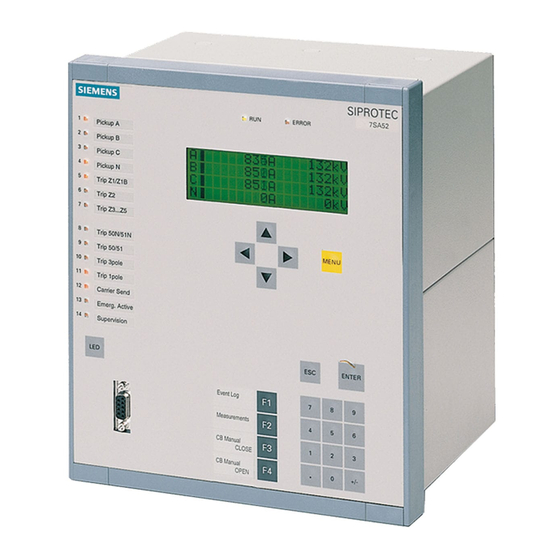
Introduction 1.1 Overall Operation Overall Operation The digital breaker management relay SIPROTEC 4 7VK61 is equipped with a powerful microprocessor system. All tasks are processed fully digitally, from the acquisition of measured values up to sending commands to the circuit breakers. Figure 1-1 shows the basic structure of the 7VK61. Analog Inputs The measuring inputs (MI) transform the currents and voltages from the instrument transformers and match them to the internal signal levels for processing in the device. - Page 17 Introduction 1.1 Overall Operation The AD analog-to-digital converter group contains analog/digital converters and memory chips for data transfer to the microcomputer system. Microcomputer System Apart from processing the measured values, the microcomputer system µC also executes the actual protection and control functions. They especially consist of: •...
-
Page 18: Application Scope
Introduction 1.2 Application Scope Application Scope The 7VK61 breaker management relay is a multi-purpose starting and control device for automatic and manual closing of circuit breakers in electrical networks of all voltage levels. The automatic reclose function may be used on overhead lines for single-pole, three-pole or single- and three- pole automatic reclosure as well as multi-shot automatic reclosure. - Page 19 Introduction 1.2 Application Scope Indications and Measured Values; Fault Recording The operational indications provide information about conditions in the power system and the device. Measure- ment quantities and values that are calculated can be displayed locally and communicated via the serial inter- faces.
-
Page 20: Characteristics
Introduction 1.3 Characteristics Characteristics General Features • Powerful 32-bit microprocessor system • complete numerical processing of measured values and control, from sampling and digitalising of the ana- logue input values up to tripping commands to the circuit breakers • complete galvanic and reliable separation between the internal processing circuits from the measurement, control, and power supply circuits by analogue input transducers, binary inputs and outputs and the DC/DC or AC voltage converters •... - Page 21 Introduction 1.3 Characteristics • Additional stage, e.g. stub protection, for fast tripping of faults between the current transformer and line iso- lator (when the isolator switching status feedback is available); particularly suitable for substation with circuit breaker arrangement 1 Circuit Breaker Failure Protection (optional) •...
- Page 22 Introduction 1.3 Characteristics Monitoring Functions • Availability of the device is greatly increased because of self-monitoring of the internal measurement circuits, power supply, hardware and software • Monitoring of the current and voltage transformer secondary circuits by means of summation and symmetry checks •...
-
Page 23: Functions
Functions This chapter describes the individual functions of the SIPROTEC 4 device 7VK61. It shows the setting possi- bilities for each function in maximum configuration. Guidelines for establishing setting values and, where re- quired, formulae are given. Based on the following information, it can also be determined which of the provided functions should be used. General Automatic reclosure function (optional) Overcurrent protection (optional) -
Page 24: General
Functions 2.1 General General A few seconds after the device is switched on, the initial display appears in the LCD. A selection of measured values is displayed. Configuration of the device functions are made via the DIGSI software from your PC. The procedure is de- scribed in detail in the SIPROTEC 4 System Description. - Page 25 Functions 2.1 General which is to be synchronized. Parameter 210 U4 voltage input U is always interpreted as the voltage U transformer is then invariably set to Usy2 transf. and excludes other setting options. Parameter 212 Usy2 connection is then set to determine which primary voltage is connected. The setting VT CONNECTION = NO hides all voltage-relevant functions and parameters.
-
Page 26: Settings
Functions 2.1 General reclosure does not have a general pickup signal for starting the action times, select ... Trip without T- action. For the trip circuit supervision set at address 140 Trip Cir. Sup. the number of trip circuits to be monitored: 1 trip circuit, 2 trip circuits or 3 trip circuits, unless you omit it (Disabled). -
Page 27: Device
Functions 2.1 General 2.1.2 Device The device requires some general information. This may be, for example, the type of indication to be issued in the event a power system fault occurs. 2.1.2.1 Trip-Dependent Indications The storing of indications masked to local LEDs, and the maintenance of spontaneous indications, can be made dependent on whether the device has issued a trip signal. -
Page 28: Settings
Functions 2.1 General 2.1.2.3 Settings Addresses which have an appended "A" can only be changed with DIGSI, under Additional Settings. Addr. Parameter Setting Options Default Setting Comments FltDisp.LED/LCD Target on PU Target on PU Fault Display on LED / LCD Target on TRIP 0 .. - Page 29 Functions 2.1 General Information Type of In- Comments formation Settings Check Settings Check Level-2 change Level-2 change Local change Local setting change Event Lost OUT_Ev Event lost Flag Lost Flag Lost Chatter ON Chatter ON ProtON/OFF IntSP Protection ON/OFF (via system port) AR ON/OFF IntSP Auto Reclose ON/OFF (via system port)
-
Page 30: Power System Data 1
Functions 2.1 General 2.1.3 Power System Data 1 The device requires some plant and power system data in order to be able to adapt its functions accordingly, dependent on the actual application. The data required include for instance rated data of the substation and the measuring transformers, polarity and connection of the measured quantities, if necessary features of the circuit breakers, and others. - Page 31 Functions 2.1 General Connection of the voltages The device features four voltage measuring inputs, three of which are connected to the set of voltage trans- formers. Various possibilities exist for the fourth voltage input U • Connection of the U input to the open delta winding e–n of the voltage transformer set: Address 210 is then set to: U4 transformer = Udelta transf..
- Page 32 Functions 2.1 General Figure 2-3 Busbar voltage measured via transformer • Connection of the U input to any other voltage signal U , which can be processed by the overvoltage pro- tection function: Address 210 is then set to: U4 transformer = Ux transformer. •...
- Page 33 Functions 2.1 General Rated frequency The nominal frequency of the system is set in address 230 Rated Frequency. The presetting according to the ordering code (MLFB) only needs to be changed if the device is applied in a region different to the one in- dicated when ordering.
-
Page 34: Settings
Functions 2.1 General 2.1.3.2 Settings Addresses which have an appended "A" can only be changed with DIGSI, under Additional Settings. Addr. Parameter Setting Options Default Setting Comments CT Starpoint towards Line towards Line CT Starpoint towards Busbar Unom PRIMARY 1.0 .. 1200.0 kV 400.0 kV Rated Primary Voltage Unom SECONDARY... -
Page 35: Change Group
Functions 2.1 General 2.1.4 Change Group 2.1.4.1 Purpose of the Setting Groups Up to four independent setting groups can be created for establishing the device's function settings. During op- eration, the user can locally switch between setting groups using the operator panel, binary inputs (if so con- figured), the operator and service interface per PC, or via the system interface. -
Page 36: Settings
Functions 2.1 General 2.1.4.3 Settings Addr. Parameter Setting Options Default Setting Comments CHANGE Group A Group A Change to Another Setting Group Group B Group C Group D Binary Input Protocol 2.1.4.4 Information List Information Type of In- Comments formation P-GrpA act IntSP Setting Group A is active... - Page 37 Functions 2.1 General Circuit breaker status Information regarding the circuit breaker position is required by various protection and supplementary functions to ensure their optimal functionality. The device has a circuit breaker status recognition which processes the status of the circuit breaker auxiliary contacts and contains also a detection based on the measured currents and voltages for opening and closing (see also Section 2.8.1).
-
Page 38: Settings
Functions 2.1 General breaker auxiliary contact must send a message that the circuit breaker is open. It is a prerequisite for this setting that the position of the auxiliary contact is allocated via a binary input. 2.1.5.2 Settings Addresses which have an appended "A" can only be changed with DIGSI, under Additional Settings. The table indicates region-specific presettings. - Page 39 Functions 2.1 General Information Type of In- Comments formation >FAIL:Feeder VT >Failure: Feeder VT (MCB tripped) >FAIL:Usy2 VT >Failure: Usy2 VT (MCB tripped) >CB1 Pole L1 >CB1 Pole L1 (for AR,CB-Test) >CB1 Pole L2 >CB1 Pole L2 (for AR,CB-Test) >CB1 Pole L3 >CB1 Pole L3 (for AR,CB-Test) >CB1 Ready >CB1 READY (for AR,CB-Test)
-
Page 40: Oscillographic Fault Records
Functions 2.1 General 2.1.6 Oscillographic Fault Records The 7VK61 breaker management relay features a fault memory. The instantaneous values of measured values and u (voltages depending on the connection) are sampled at intervals of 1 ms (for 50 Hz) and stored in a circulating buffer (20 samples per cycle). -
Page 41: Settings
Functions 2.1 General Pre-fault and post-fault times will be included. If the binary input time is set for ∞, then the length of the record equals the time that the binary input is activated (static), or the MAX. LENGTH setting in address 410, which- ever is shorter. -
Page 42: Ethernet En100-Module
Functions 2.1 General 2.1.7 Ethernet EN100-Module 2.1.7.1 Function Description An Ethernet EN100-Module allows to integrate the 7VK61 into 100 Mbit communication networks used by process control and automation systems in accordance with IEC 61850. This standard provides consistent inter-relay communication without gateways or protocol converters. This allows open and interoperable use of SIPROTEC 4 devices even in heterogeneous environments. -
Page 43: Automatic Reclosure Function (Optional)
Functions 2.2 Automatic reclosure function (optional) Automatic reclosure function (optional) Experience shows that about 85% of the arc faults on overhead lines are extinguished automatically after being tripped by the protection. The line can therefore be re-energised. Reclosure is performed by an automatic reclose function (AR). - Page 44 Functions 2.2 Automatic reclosure function (optional) The integrated automatic reclosing function allows up to 8 reclosing attempts. The first four reclose cycles may operate with different parameters (action and dead times, single-/three-pole). The parameters of the fourth cycle apply to the fifth cycle and onwards. Selectivity before Reclosure In order for automatic reclosing to be successful, all faults occurring on the entire line length must be cleared at both line ends simultaneously —...
- Page 45 Functions 2.2 Automatic reclosure function (optional) Those protection and monitoring functions in the device which do not respond to short-circuits or similar con- ditions (e.g. an overload protection) do not initiate the automatic reclosure function because a reclosure will be of no use here.
- Page 46 Functions 2.2 Automatic reclosure function (optional) reclosure operating mode selected when determining the function scope and the resulting signals of the starting protective functions. In control mode TRIP... (With TRIP command ...) single-pole or single-/three-pole reclose cycles are possible if the device and the circuit breaker are suitable. In this case, different dead times (for every AR cycle) are pos- sible after single-pole tripping and after three-pole tripping.
- Page 47 Functions 2.2 Automatic reclosure function (optional) Especially when multiple reclosing attempts are programmed, it is recommended to monitor the circuit breaker condition not only prior to the first, but also before each following reclosing attempt. Reclosure will be blocked until the binary input indicates that the circuit breaker is ready to complete another CLOSE-TRIP cycle. The time needed by the circuit breaker to regain the ready state can be monitored by the 7VK61.
- Page 48 Functions 2.2 Automatic reclosure function (optional) If the fault has not been eliminated (unsuccessful reclosure), the short-circuit protection initiates a final trip fol- lowing a protection stage active without reclosure. Any fault during the reclaim time leads to a final trip. After unsuccessful reclosure (final tripping) the automatic reclosure is blocked dynamically (see also margin heading „Reclose Block“, above).
- Page 49 Functions 2.2 Automatic reclosure function (optional) If the fault is cleared (successful reclosure), the reclaim time expires and all functions return to their quiescent state. The fault is cleared. If the fault has not been eliminated (unsuccessful reclosure), the short-circuit protection initiates a final three- pole trip with the protection stage valid without reclosure.
- Page 50 Functions 2.2 Automatic reclosure function (optional) There are also various selectable possibilities for the response of the internal auto- reclose function to a de- tected evolving fault. • EV. FLT. MODE blocks AR: The reclosure is blocked as soon as a sequential fault is detected. The tripping by the sequential fault is always three-pole.
- Page 51 Functions 2.2 Automatic reclosure function (optional) Figure 2-6 Example of a reduced dead time (RDT) A, B, C Busbars I, II, III Relay locations Tripped circuit breakers Adaptive Dead Time (ADT) In all the previous alternatives it was assumed that defined and equal dead times were set at both line ends, if necessary for different fault types and/or reclose cycles.
- Page 52 Functions 2.2 Automatic reclosure function (optional) As is shown by the example, the adaptive dead time has the following advantages: • The circuit breaker at position II is not reclosed at all if the fault persists and is not unnecessarily stressed as a result.
- Page 53 Functions 2.2 Automatic reclosure function (optional) To achieve three pole coupling of the external protection and to release, if necessary, its accelerated stages before reclosure, the following output functions are suitable: 2864 „AR 1p Trip Perm“ Internal automatic reclosure function ready for single-pole reclose cycle, i.e. allows single-pole tripping (logic inversion of the three-pole coupling).
- Page 54 Functions 2.2 Automatic reclosure function (optional) Figure 2-9 Connection example with external protection device for 3-pole reclosure; AR control mode = with TRIP If, however, the internal automatic reclose function is controlled by the pickup, the phase-dedicated pickup signals of the external protection must be connected if distinction shall be made between different types of fault. The general trip command then suffices for tripping (FNo.
-
Page 55: Setting Notes
Functions 2.2 Automatic reclosure function (optional) Section 2.2.2 at margin heading „Forced three-pole trip“). An external automatic three-pole coupling is there- fore unnecessary if the above conditions are met. This prevents two-pole tripping under all circumstances. Figure 2-11 Connection example for 2 protection devices with 2 automatic reclosure functions 2.2.2 Setting Notes General... - Page 56 Functions 2.2 Automatic reclosure function (optional) A prerequisite for automatic reclosure taking place after a trip due to a short-circuit is that the circuit breaker is ready for at least one OPEN-CLOSE-OPEN cycle at the time the automatic reclosure circuit is started, i.e. at the time of the first trip command.
- Page 57 Functions 2.2 Automatic reclosure function (optional) Address 3408 T-Start MONITOR monitors the reaction of the circuit breaker after a trip command. If the CB has not opened during this time (from the beginning of the trip command), the automatic reclosure is blocked dynamically.
- Page 58 Functions 2.2 Automatic reclosure function (optional) Adaptive Dead Time (ADT) When operating with adaptive dead time, it must be ensured in advance that one end per line operates with defined dead times and has an infeed. The other (or the others in multi-branch lines) may operate with adaptive dead time.
- Page 59 Functions 2.2 Automatic reclosure function (optional) pected during three-pole dead times (e.g. due to closely meshed networks or in radial networks), set address 3437 to NO. Addresses 3438 and 3440 are only significant if the voltage-controlled adaptive dead time is used. 3440 U- live>...
- Page 60 Functions 2.2 Automatic reclosure function (optional) time may be tolerated under certain circumstances. Longer three-pole dead times are also possible in radial networks. For AR control mode = with PICKUP ... it is possible to make the dead times dependent on the type of fault detected by the initiating protection function(s).
- Page 61 Functions 2.2 Automatic reclosure function (optional) For the 3rd cycle: 3472 3.AR: START Start in 3rd cycle generally allowed 3473 3.AR: T-ACTION Action time for the 3rd cycle 3475 3.AR Tdead 1Flt Dead time after single-phase pickup 3476 3.AR Tdead 2Flt Dead time after two-phase pickup 3477 3.AR Tdead 3Flt Dead time after three-phase pickup...
-
Page 62: Settings
Functions 2.2 Automatic reclosure function (optional) „AR is blocked“ (No. 2783) The automatic reclosure is blocked (e.g. circuit breaker not ready). This information indicates to the operational information system that in the event of an upcoming system fault there will be a final trip, i.e. without reclosure. If the automatic reclosure has been started, this information does not appear. - Page 63 Functions 2.2 Automatic reclosure function (optional) Addr. Parameter Setting Options Default Setting Comments 3407 EV. FLT. MODE blocks AR starts 3p AR Evolving fault (during the dead starts 3p AR time) 3408 T-Start MONITOR 0.01 .. 300.00 sec 0.20 sec AR start-signal monitoring time 3409 CB TIME OUT...
- Page 64 Functions 2.2 Automatic reclosure function (optional) Addr. Parameter Setting Options Default Setting Comments 0.01 .. 300.00 sec; ∞ 3462 2.AR: T-ACTION 0.20 sec Action time 0.01 .. 1800.00 sec; ∞ 3464 2.AR Tdead 1Flt 1.20 sec Dead time after 1phase faults 0.01 ..
-
Page 65: Information List
Functions 2.2 Automatic reclosure function (optional) 2.2.4 Information List Information Type of In- Comments formation 2701 >AR on >AR: Switch on auto-reclose function 2702 >AR off >AR: Switch off auto-reclose function 2703 >AR block >AR: Block auto-reclose function 2711 >AR Start >External start of internal Auto reclose 2712 >Trip L1 AR... - Page 66 Functions 2.2 Automatic reclosure function (optional) Information Type of In- Comments formation 2843 AR Tdead 3pFlt AR dead time after 3phase fault running 2844 AR 1stCyc. run. AR 1st cycle running 2845 AR 2ndCyc. run. AR 2nd cycle running 2846 AR 3rdCyc.
-
Page 67: Overcurrent Protection (Optional)
Functions 2.3 Overcurrent protection (optional) Overcurrent protection (optional) The 7VK61 features a time overcurrent protection function with four independent stages that can be combined freely with one another. 2.3.1 General For the overcurrent protection there are in total four stages for the phase currents and four stages for the earth currents as follows: •... - Page 68 Functions 2.3 Overcurrent protection (optional) Figure 2-12 Logic diagram of the I>> stage The output indications associated with the trip signals can be found in Table 2-3 The output indications associated with the trip signals can be found in Table 2-4 Definite time overcurrent stage I>...
- Page 69 Functions 2.3 Overcurrent protection (optional) The following figure shows the logic diagram. The setting addresses of the IEC characteristics are shown by way of an example. In the setting information (Subsection 2.3.3) the different setting addresses are elaborated upon. Figure 2-13 Logic diagram of the I stage (inverse time overcurrent protection), for example IEC characteristics The output indications associated with the pickup signals can be found in Table 2-3...
- Page 70 Functions 2.3 Overcurrent protection (optional) End fault protection A further overcurrent stage is the stub protection. It can however also be used as a normal additional definite time overcurrent stage, as it functions independent of the other stages. A stub fault is a short-circuit located between the current transformer set and the line isolator. It is of particular importance with the 1 circuit breaker arrangements.
- Page 71 Functions 2.3 Overcurrent protection (optional) Figure 2-15 Logic diagram of stub fault protection The output indications associated with the pickup signals can be found in Table 2-3 The output indications associated with the trip signals can be found in Table 2-4 Instantaneous tripping before automatic reclosure If automatic reclosure must be performed, a quick clearance of the fault before reclosure is usually desirable.
- Page 72 Functions 2.3 Overcurrent protection (optional) Switching onto a fault To achieve fast tripping of the circuit breaker in the event of an earth fault, the manual CLOSE detection function can be used. The time overcurrent protection can then trip three-pole without delay or with a reduced delay. It can be determined via parameter settings for which stage(s) the instantaneous tripping following energisation applies (see also the logic diagrams Figure 2-12, 2-13 and 2-15).
-
Page 73: Setting Notes
Functions 2.3 Overcurrent protection (optional) Table 2-4 Trip signals of the single phases Internal Indication Display Output Indication I>> TRIP L1 2-12 I> TRIP L1 7212 or „O/C TRIP 1p.L1“ or „O/C TRIP L123“ Ip TRIP L1 2-13 7215 I>>> TRIP L1 2-15 I>>... - Page 74 Functions 2.3 Overcurrent protection (optional) High-current elements I >>, 3I >> The I>> stages Iph>> (address 2610) and 3I0>> PICKUP (address 2612) together with the I> stages or the stages result in a two-stage characteristic. Of course, all three stages can be combined as well. If one stage is not required, the pickup value has to be set to ∞.
- Page 75 Functions 2.3 Overcurrent protection (optional) Note: the calculation was carried out with absolute values, which is sufficiently precise for overhead lines. If the angles of the source impedance and the line impedance vary considerably, a complex calculation must be carried out. A similar calculation must be carried out for earth faults, with the maximum earth current occurring at the line end during a short-circuit being decisive.
- Page 76 Functions 2.3 Overcurrent protection (optional) The set times are mere additional delays for the independent stages, which do not include the inherent oper- ating time of the protection. If only the phase currents are to be monitored, set the pickup value of the earth fault stage to ∞.
- Page 77 Functions 2.3 Overcurrent protection (optional) function as energizing of the line on to a fault should cause a large fault current. It is important to avoid that the selected stage picks up due to transients during line energization. Overcurrent StagesI , 3I for inverse time overcurrent protection with ANSI characteristics In the case of the inverse overcurrent stages, various characteristics can be selected, depending on the order-...
-
Page 78: Settings
Functions 2.3 Overcurrent protection (optional) sible that high short circuit currents flow from busbar A to busbar B or to feeder 2 via the current transformers. These currents could cause different transformation errors in the two current transformer sets I and I , espe- cially in the saturation range. - Page 79 Functions 2.3 Overcurrent protection (optional) Addr. Parameter Setting Options Default Setting Comments 2625 I> SOTF Instantaneous trip after SwitchOnToFault 0.10 .. 25.00 A; ∞ 2630 Iph> STUB 1.50 A Iph> STUB Pickup 0.50 .. 125.00 A; ∞ 7.50 A 0.00 .. 30.00 sec; ∞ 2631 T Iph STUB 0.30 sec...
-
Page 80: Information List
Functions 2.3 Overcurrent protection (optional) 2.3.5 Information List Information Type of In- Comments formation 7104 >BLOCK O/C I>> >BLOCK Backup OverCurrent I>> 7105 >BLOCK O/C I> >BLOCK Backup OverCurrent I> 7106 >BLOCK O/C Ip >BLOCK Backup OverCurrent Ip 7110 >O/C InstTRIP >Backup OverCurrent InstantaneousTrip 7130 >BLOCK I-STUB... -
Page 81: Synchronism And Voltage Check (Optional)
Functions 2.4 Synchronism and voltage check (optional) Synchronism and voltage check (optional) The synchronism and voltage check function ensures, when switching a line onto a busbar, that the stability of the network is not endangered. The voltage of the feeder to be energized is compared to that of the busbar to check conformances in terms of magnitude, phase angle and frequency within certain tolerances. - Page 82 Functions 2.4 Synchronism and voltage check (optional) Figure 2-17 Synchronism check across a transformer - example The synchronism check function in the 7VK61 usually operates in conjunction with the integrated automatic reclose, manual close, and the control functions of the relay. It is also possible to employ an external automatic reclosing system.
- Page 83 Functions 2.4 Synchronism and voltage check (optional) • Measuring request from the manual CLOSE detection. The manual CLOSE detection of the central function control (Section 2.8.1) issues a measuring request provided that this was configured in the power system data 2 (Section 2.1.5.1, address 1151). This requires that the device is informed of the manual closing via binary input „>Manual Close“...
- Page 84 Functions 2.4 Synchronism and voltage check (optional) SIPROTEC, 7VK61, Manual C53000-G1176-C159-3, Release date 05.2009...
- Page 85 Functions 2.4 Synchronism and voltage check (optional) Figure 2-18 Synchro check logic Operating modes The closing check for automatic reclosing is possible in one of the following operating modes: AR SYNC-CHECK Released at synchronism, that is when the critical values AR maxVolt.Diff, AR maxFreq.Diff, AR maxAngleDiff are within the set limits.
- Page 86 Functions 2.4 Synchronism and voltage check (optional) The closing check for manual reclosing is possible in one of the following operating modes: MC SYNCHR Released at synchronism, that is when the critical values MC maxVolt.Diff, MC maxFreq.Diff, MC maxAngleDiff are within the set limits.
-
Page 87: Setting Notes
Functions 2.4 Synchronism and voltage check (optional) Closing under asynchronous system conditions Before releasing a closing command at asynchronous conditions, the following conditions are checked: • Is the busbar voltage above the setting value Live Volt. Thr. but below the maximum voltage Umax? •... - Page 88 Functions 2.4 Synchronism and voltage check (optional) 230 Rated Frequency the operating range of the synchronism check refers to the nominal frequen- ± 3 Hz); cy of the power system (f 1103 FullScaleVolt. Nominal operational voltage of the primary power system (phase-phase) in and, if closing at asynchronous system conditions is allowed, 239 T-CB close the closing time of the circuit breaker.
- Page 89 Functions 2.4 Synchronism and voltage check (optional) For switching under non-asynchronous conditions, you can also set a delay T SYNC-STAB (address 3508) during which the voltage conditions must at least be satisfied before closing is released. Synchronism conditions for automatic reclosure Addresses 3510 to 3519 are relevant to the check conditions before automatic reclosure of the circuit breaker.
- Page 90 Functions 2.4 Synchronism and voltage check (optional) you set SyncCB = none here, a CLOSE command via the integrated control will be carried out without syn- chronism check. Address 3530 Op.mode with MC determines whether closing under asynchronous system conditions is allowed for manual closing or reclosure via control command.
- Page 91 Functions 2.4 Synchronism and voltage check (optional) Notes on the Information List The most important information of the device is briefly explained in so far as it cannot be interpreted in the fol- lowing information lists or described in detail in the foregoing text. „>Sync.
- Page 92 Functions 2.4 Synchronism and voltage check (optional) Figure 2-19 Example of a three-phase phase-to-earth connection Connection, single-phase , parameter106 is set to VT CONNECTION If only a single-phase voltage is available as reference voltage U = 1phase during configuration. If this type of connection is used, the reference voltage U must always be connected to the voltage input U of the 7VK61, regardless of the phase actually used at the primary voltage...
-
Page 93: Settings
Functions 2.4 Synchronism and voltage check (optional) Figure 2-20 Example of a single-phase phase-to-earth connection 2.4.3 Settings Addresses which have an appended "A" can only be changed with DIGSI, under Additional Settings. Addr. Parameter Setting Options Default Setting Comments 3501 FCT Synchronism Synchronism and Voltage Check function... -
Page 94: Information List
Functions 2.4 Synchronism and voltage check (optional) Addr. Parameter Setting Options Default Setting Comments 3517 AR Usy1>Usy2< AR at Usy1> and Usy2< 3518 AR Usy1<Usy2< AR at Usy1< and Usy2< 3519 AR OVERRIDE Override of any check before AR 3530 Op.mode with MC with T-CB close w/o T-CB close... - Page 95 Functions 2.4 Synchronism and voltage check (optional) Information Type of In- Comments formation 2944 SYNC Usy1>Usy2< SYNC Condition Usy1>Usy2< true 2945 SYNC Usy1<Usy2> SYNC Condition Usy1<Usy2> true 2946 SYNC Usy1<Usy2< SYNC Condition Usy1<Usy2< true 2947 Sync. Udiff> Sync. Voltage diff. greater than limit 2948 Sync.
-
Page 96: Under And Over-Voltage Protection (Optional)
Functions 2.5 Under and over-voltage protection (optional) Under and over-voltage protection (optional) Voltage protection has the function of protecting electrical equipment against undervoltage and overvoltage. Both operational states are unfavourable as overvoltage may cause, for example, insulation problems or und- ervoltage may cause stability problems. - Page 97 Functions 2.5 Under and over-voltage protection (optional) Figure 2-21 Logic diagram of the overvoltage protection for phase voltage Phase-phase overvoltage The phase–phase overvoltage protection operates just like the phase–earth protection except that it detects phase–to–phase voltages. Accordingly, phase–to–phase voltages which have exceeded one of the stage thresholds Uph-ph>...
- Page 98 Functions 2.5 Under and over-voltage protection (optional) Overvoltage positive sequence systemU The device calculates the positive sequence system according to its defining equation ·(U + a·U ·U j120° where a = e The resulting single–phase AC voltage is fed to the two threshold stages U1> and U1>> (see Figure 2-22). Combined with the associated time delays T U1>...
- Page 99 Functions 2.5 Under and over-voltage protection (optional) Figure 2-23 Logic diagram of the overvoltage protection for the negative sequence voltage system U The overvoltage protection for the negative sequence system can also be blocked via a binary input „>U2>(>) BLK“. The stages of the negative sequence voltage protection are automatically blocked as soon as an asym- metrical voltage failure was detected („Fuse–Failure–Monitor“, also see Section 2.7.1, margin heading „Fuse Failure Monitor (Non-symmetrical Voltages))“...
- Page 100 Functions 2.5 Under and over-voltage protection (optional) zero sequence system. Here too, the drop-off to pickup ratio can be set (3U0>(>) RESET). Furthermore, a restraint delay can be configured which is implemented by repeated measuring (approx. 3 periods). The overvoltage protection for the zero sequence system can also be blocked via a binary input „>3U0>(>) BLK“.
- Page 101 Functions 2.5 Under and over-voltage protection (optional) Figure 2-24 Logic diagram of the overvoltage protection for zero sequence voltage Freely selectable single-phase voltage As the zero sequence voltage stages operate separately and independent from the other protective overvoltage functions they can be used for any other single–phase voltage. Therefore the fourth voltage input U of the device must be assigned accordingly (also see Section 2.1.3, „Voltage Transformer Connection“).
-
Page 102: Undervoltage Protection
Functions 2.5 Under and over-voltage protection (optional) 2.5.2 Undervoltage protection Undervoltage Phase–Earth Figure 2-25 depicts the logic diagram of the phase voltage stages. The fundamental frequency is numerically filtered from each of the three measuring voltages so that harmonics or transient voltage peaks are largely harmless. - Page 103 Functions 2.5 Under and over-voltage protection (optional) Figure 2-25 Logic diagram of the undervoltage protection for phase voltages Phase-phase undervoltage Basically, the phase-phase undervoltage protection operates like the phase-earth protection except that it detects phase-to-phase voltages. Accordingly, both phases are indicated during pickup of an undervoltage stage if one of the stage thresholds Uph-ph<...
- Page 104 Functions 2.5 Under and over-voltage protection (optional) The phase–phase undervoltage protection can also be blocked via a binary input „>Uphph<(<) BLK“. There is an automatic blocking if the measuring voltage failure was detected or voltage mcb tripping was indicated (internal blocking of the phases affected by the voltage failure). During single-pole dead time for automatic reclosure the stages of the undervoltage protection are automati- cally blocked in the disconnected phase so that it does not respond to the undervoltage of the disconnected phase provided that the voltage transformers are located on the outgoing side.
- Page 105 Functions 2.5 Under and over-voltage protection (optional) Figure 2-26 Logic diagram of the undervoltage protection for positive sequence voltage system During single-pole dead time for automatic reclosure the stages of the undervoltage protection are automati- cally blocked in the positive sequence system so that they do not respond to the reduced voltage caused by the disconnected phase in case the voltage transformers are located on the outgoing side.
-
Page 106: Setting Notes
Functions 2.5 Under and over-voltage protection (optional) 2.5.3 Setting Notes General The voltage protection can only operate if it has been set to 137 during the configuration of the device scope (address Enabled). The overvoltage and undervoltage stages can detect phase-to-earth voltages, phase-to-phase voltages or the symmetrical positive sequence system of the voltages;... - Page 107 Functions 2.5 Under and over-voltage protection (optional) Overvoltage positive sequence systemU You can use the positive sequence voltage stages instead of or in addition to previously mentioned overvoltage stages. Depending on your choice, set address 3731 U1>(>) to ON, OFF, Alarm Only or U>Alarm U>>Trip.
- Page 108 Functions 2.5 Under and over-voltage protection (optional) The dropout to pickup ratio 3U0>(>) RESET can be set in address 3729. This parameter can only be altered in DIGSI at Display Additional Settings. When setting the voltage values please observe the following: •...
-
Page 109: Settings
Functions 2.5 Under and over-voltage protection (optional) If the voltage transformers are located on the line side, the measuring voltages will be missing when the line is disconnected. To avoid that the undervoltage levels in these cases are or remain picked up, the current criterion CURR.SUP.Uphph<... - Page 110 Functions 2.5 Under and over-voltage protection (optional) Addr. Parameter Setting Options Default Setting Comments 0.00 .. 100.00 sec; ∞ 3713 T Uph-ph> 2.00 sec T Uph-ph> Time Delay 2.0 .. 220.0 V; ∞ 3714 Uph-ph>> 175.0 V Uph-ph>> Pickup 0.00 .. 100.00 sec; ∞ 3715 T Uph-ph>>...
-
Page 111: Information List
Functions 2.5 Under and over-voltage protection (optional) Addr. Parameter Setting Options Default Setting Comments 3759A Uph-e<(<) RESET 1.01 .. 1.20 1.05 Uph-e<(<) Reset ratio 3761 Uph-ph<(<) Operating mode Uph-ph under- Alarm Only voltage prot. U<Alarm U<<Trip 3762 Uph-ph< 1.0 .. 175.0 V; 0 50.0 V Uph-ph<... - Page 112 Functions 2.5 Under and over-voltage protection (optional) Information Type of In- Comments formation 10222 U1>(>) BLK U1>(>) Overvolt. is BLOCKED 10223 U2>(>) OFF U2>(>) Overvolt. is switched OFF 10224 U2>(>) BLK U2>(>) Overvolt. is BLOCKED 10225 Uph-e<(<) OFF Uph-e<(<) Undervolt. is switched OFF 10226 Uph-e<(<) BLK Uph-e<(<) Undervolt.
- Page 113 Functions 2.5 Under and over-voltage protection (optional) Information Type of In- Comments formation 10283 U1>> TimeOut U1>> TimeOut 10284 U1>(>) TRIP U1>(>) TRIP command 10290 U2> Pickup U2> Pickup 10291 U2>> Pickup U2>> Pickup 10292 U2> TimeOut U2> TimeOut 10293 U2>>...
-
Page 114: Circuit Breaker Failure Protection (Optional)
Functions 2.6 Circuit breaker failure protection (optional) Circuit breaker failure protection (optional) The circuit breaker failure protection provides rapid back-up fault clearance in the event that the circuit breaker fails to respond to a trip command from a protective function of the local circuit breaker. 2.6.1 Method of Operation General... - Page 115 Functions 2.6 Circuit breaker failure protection (optional) Figure 2-28 Simplified function diagram of circuit breaker failure protection controlled by circuit breaker aux- iliary contact Current flow monitoring Each of the phase currents and an additional plausibility current (see below) are filtered by numerical filter al- gorithms so that only the fundamental component is used for further evaluation.
- Page 116 Functions 2.6 Circuit breaker failure protection (optional) Figure 2-29 Current flow monitoring with plausibility currents 3·I and 3·I Monitoring the circuit breaker auxiliary contacts It is the central function control of the device that informs the breaker failure protection on the position of the circuit breaker (refer also to Section 2.8.1).
- Page 117 Functions 2.6 Circuit breaker failure protection (optional) Figure 2-30 Interlock of the auxiliary contact criterion - example for phase L1 if phase-segregated auxiliary contacts are available if series-connected NC contacts are available On the other hand, current flow is not a reliable criterion for proper operation of the circuit breaker for faults which do not cause detectable current flow (e.g.
- Page 118 Functions 2.6 Circuit breaker failure protection (optional) Creation of signal "CB ≥ any pole closed" Figure 2-31 If the trip is generated by an internal protection function or by an external protection device whose operating principle is not necessarily associated with current flow, this is processed internally via the input „Start internal w/o I“...
- Page 119 Functions 2.6 Circuit breaker failure protection (optional) Phase-segregated initiation Phase segregated initiation of the breaker failure protection is necessary if the circuit breaker poles are oper- ated individually, e.g. if single-pole automatic reclosure is used. This is possible if the device is able to trip single-pole.
- Page 120 Functions 2.6 Circuit breaker failure protection (optional) Initiation of an individual phase, e.g. „Start only L1“, is only valid if the starting signal (= tripping signal of the feeder protection) appears for exactly this phase and if the current criterion is met for at least this phase. If it is not met, the circuit breaker auxiliary contact can be interrogated according to Figure 2-30 –...
- Page 121 Functions 2.6 Circuit breaker failure protection (optional) Figure 2-35 Initiation conditions for single-pole trip commands SIPROTEC, 7VK61, Manual C53000-G1176-C159-3, Release date 05.2009...
- Page 122 Functions 2.6 Circuit breaker failure protection (optional) Delay times When the initiate conditions are fulfilled, the associated timers are started. The circuit breaker pole(s) must open before the associated time has elapsed. Different delay times are possible for single-pole and three-pole initiation. An additional delay time can be used for two-stage breaker failure protection.
- Page 123 Functions 2.6 Circuit breaker failure protection (optional) Address 3913 T2StartCriteria is used to set whether the delay time T2 is started after expiration of the time T1 (T2StartCriteria = With exp. of T1) or parallel to this time (T2StartCriteria = Parallel withT1).
- Page 124 Functions 2.6 Circuit breaker failure protection (optional) started (Figure 2-39). Thus, the adjacent circuit breakers (bus-bar) are tripped immediately in case the feeder circuit breaker is not operational. Figure 2-39 Circuit breaker faulty Transfer trip to the remote end circuit breaker The device has the facility to provide an additional intertrip signal to the circuit breaker at the remote line end in the event that the local feeder circuit breaker fails.
- Page 125 Functions 2.6 Circuit breaker failure protection (optional) signal. Figure 2-41 illustrates the functional principle. If the breaker failure protection is initiated and current flow is detected (current criteria „L*> current criterion“ according to Figure 2-29), but no circuit breaker pole is closed (auxiliary contact criterion „...
-
Page 126: Setting Notes
Functions 2.6 Circuit breaker failure protection (optional) 2.6.2 Setting Notes General The circuit breaker failure protection and its ancillary functions (end fault protection, pole discrepancy supervi- sion) can only operate if they were set during configuration of the scope of functions (address 139 BREAKER FAILURE, setting Enabled or enabled w/ 3I0>). - Page 127 Functions 2.6 Circuit breaker failure protection (optional) Note If the breaker failure protection is to perform a single-pole TRIP repetition, the time set for the AR, address 3408 T-Start MONITOR, has to be longer than the time set for address 3903 1p-RETRIP (T1) to prevent 3-pole coupling by the AR before T1 expires.
- Page 128 Functions 2.6 Circuit breaker failure protection (optional) Figure 2-44 Time sequence example for normal clearance of a fault, and with circuit breaker failure, using single-stage breaker failure protection Circuit breaker not operational If the circuit breaker associated with the feeder is not operational (e.g. control voltage failure or air pressure failure), it is apparent that the local breaker cannot clear the fault.
-
Page 129: Settings
Functions 2.6 Circuit breaker failure protection (optional) vision issues a three-pole trip command. This time must be clearly longer than the duration of a single-pole automatic reclose cycle. The time should be less than the permissible duration of an unbalanced load condition which is caused by the unsymmetrical position of the circuit breaker poles. -
Page 130: Information List
Functions 2.6 Circuit breaker failure protection (optional) 2.6.4 Information List Information Type of In- Comments formation 1401 >BF on >BF: Switch on breaker fail protection 1402 >BF off >BF: Switch off breaker fail protection 1403 >BLOCK BkrFail >BLOCK Breaker failure 1415 >BF Start 3pole >BF: External start 3pole... -
Page 131: Monitoring Function
Functions 2.7 Monitoring Function Monitoring Function The device incorporates extensive monitoring functions of both the device hardware and software; the mea- sured values are also continually checked to ensure their plausibility; the current and voltage transformer sec- ondary circuits are thereby substantially covered by the monitoring function. It is also possible to implement trip circuit monitoring, using appropriate binary inputs as available. - Page 132 Functions 2.7 Monitoring Function Offset of the Analogue-to-Digital Converter The offset of the ADC is measured cyclically for each channel and corrected. When the offset reaches an in- admissibly high value, the indication „Error Offset“ (No. 191) is displayed. The protective functions remain active.
-
Page 133: Software Monitoring
Functions 2.7 Monitoring Function Measured value acquisition voltages Four measuring inputs are available in the voltage circuit: three for phase-to-earth voltages and one input for the displacement voltage (e-n voltage of open delta winding) or a busbar voltage. If the displacement voltage is connected to the device, the sum of the three digitized phase voltages must equal three times the zero se- quence voltage. - Page 134 Functions 2.7 Monitoring Function Figure 2-46 Current symmetry monitoring Broken Conductor A broken wire of the protected line or in the current transformer secondary circuit can be detected if a minimum current PoleOpenCurrent flows via the line. If the minimum phase current is below this limit while the other phase currents are above this limit, an interruption of this conductor may be assumed.
- Page 135 Functions 2.7 Monitoring Function Figure 2-47 Voltage symmetry monitoring Voltage Phase Sequence Verification of the faulted phases, phase preference, direction measurement and polarisation with quadrature voltages usually require clockwise rotation of the measured values. The phase rotation of the measured volt- ages is checked by monitoring the voltage phase sequence before U before U...
- Page 136 Functions 2.7 Monitoring Function if both the zero sequence as well as the negative sequence current are below the settable threshold FFM I< (max) . As soon as this state is recognized, the undervoltage protection and the two overvoltage stages U and 3U are blocked.
- Page 137 Functions 2.7 Monitoring Function Three-Phase Measuring Voltage Failure "Fuse Failure Monitor" A three-phase failure of the secondary measured voltages can be distinguished from an actual system fault by the fact that the currents have no significant change in the event of a failure in the secondary measured voltage. For this reason, the current values are routed to a buffer so that the difference between present and stored current values can be analysed to recognise the magnitude of the current differential (current differential crite- rion).
-
Page 138: Monitoring The Phase Angle Of The Positive Sequence Power
Functions 2.7 Monitoring Function Figure 2-49 Logic diagram of the additional measured voltage failure monitoring 2.7.1.4 Monitoring the Phase Angle of the Positive Sequence Power This monitoring function allows to determine the direction of power flow. You can monitor the phase angle of the complex power, and generate an indication when the power phasor is inside a settable segment. - Page 139 Functions 2.7 Monitoring Function Figure 2-50 Characteristic of the Positive Sequence System Phase Angle Monitoring The monitoring function can also be used for the display of negative active power. In this case the areas must be defined as shown in Figure 2-51. SIPROTEC, 7VK61, Manual C53000-G1176-C159-3, Release date 05.2009...
- Page 140 Functions 2.7 Monitoring Function Figure 2-51 Phase Angle Monitoring for Negative Active Power The two angles must be at least 3° apart; if this is not the case, monitoring is blocked and the indication „ϕ Set wrong“ (No. 132) is output. The following conditions must be fulfilled for measurement to be enabled: is higher than the value set in parameter 2943 I1>.
-
Page 141: Malfunction Reaction
Functions 2.7 Monitoring Function Figure 2-52 Logic of the Positive Sequence System Phase Angle Monitoring 2.7.1.5 Malfunction Reaction Depending which kind of self supervision function is picked up, an alarm is given, the processor is restarted or the device is taken out of operation. If the fault is still present after three restart attempts, the device will take itself out of service and indicate this condition by dropout of the “Device OK”... - Page 142 Functions 2.7 Monitoring Function Monitoring possible causes Malfunction Re- Message (F.No) Device sponse 1 A/5 A-Setting Jumper wrong 1/5 A Indications: „Error1A/5Awrong“ drops out Protection out of opera- (192) „Error A/D- tion conv.“ (181) LED „ERROR“ Calibration data Internal (EEPROM or RAM) Indication: „Alarm adjustm.“...
-
Page 143: Setting Notes
Functions 2.7 Monitoring Function 2.7.1.6 Setting Notes General The sensitivity of the measured value monitoring can be changed. Experiential values set ex works are ade- quate in most cases. If particularly high operational asymmetries of the currents and/or voltages are expected, or if one or more monitoring functions pick up sporadically during normal operation, the sensitivity setting(s) should be reduced. -
Page 144: Settings
Functions 2.7 Monitoring Function 2.7.1.7 Settings Addresses which have an appended "A" can only be changed with DIGSI, under Additional Settings. The table indicates region-specific presettings. Column C (configuration) indicates the corresponding second- ary nominal current of the current transformer. Addr. -
Page 145: Information List
Functions 2.7 Monitoring Function 2.7.1.8 Information List Information Type of In- Comments formation ϕ(PQ Pos. Seq.) Load angle Phi(PQ Positive sequence) ϕ(PQ Pos) block Load angle Phi(PQ) blocked ϕ Set wrong Setting error: |PhiA - PhiB| < 3° Fail I Superv. Failure: General Current Supervision Failure Σ... - Page 146 Functions 2.7 Monitoring Function Figure 2-53 Principle of trip circuit monitoring with two binary inputs Monitoring with two binary inputs not only detects interruptions in the trip circuit and loss of control voltage, it also supervises the response of the circuit breaker using the position of the circuit breaker auxiliary contacts. Depending on the conditions of the trip contact and the circuit breaker, the binary inputs are activated (logical condition „H“...
- Page 147 Functions 2.7 Monitoring Function Figure 2-54 Logic diagram of the trip circuit monitoring with two binary inputs Supervision with One Binary Input The binary input is connected in parallel to the respective command relay contact of the protection device ac- cording to Figure 2-55.
-
Page 148: Setting Notes
Functions 2.7 Monitoring Function Figure 2-56 Logic diagram for trip circuit supervision with one binary input 2.7.2.2 Setting Notes General The number of circuits to be supervised was set during the configuration in address 140 Trip Cir. Sup. (Section 2.1.1.2). If the trip circuit supervision is not used at all, the setting Disabled must be applied there. The trip circuit supervision can be switched ON or OFF in address 4001 FCT TripSuperv.. -
Page 149: Settings
Functions 2.7 Monitoring Function 2.7.2.3 Settings Addr. Parameter Setting Options Default Setting Comments 4001 FCT TripSuperv. TRIP Circuit Supervision is 4002 No. of BI 1 .. 2 Number of Binary Inputs per trip circuit 4003 Alarm Delay 1 .. 30 sec 2 sec Delay Time for alarm 2.7.2.4 Information List... -
Page 150: Function Control
Functions 2.8 Function Control Function Control 2.8.1 General The function control is the control centre of the device. It coordinates the sequence of the protection and ancil- lary functions, processes their decisions and the information coming from the power system. Applications •... - Page 151 Functions 2.8 Function Control Reclosure via the integrated control functions - on-site control, control via DIGSI, control via serial interface - can have the same effect as manual closure, see parameter 1152 Chapter 2.1.5.1 at margin heading „Circuit Breaker Status“. If the device has an integrated automatic reclosure, the integrated manual closure logic of the 7VK61 automat- ically distinguishes between an external control command via the binary input and an automatic reclosure by the internal automatic reclosure so that the binary input „>Manual Close“...
-
Page 152: Detection Of The Circuit Breaker Position
Functions 2.8 Function Control Figure 2-59 Manual closing with external automatic reclosure device Circuit breaker Circuit breaker close coil CBaux Circuit breaker auxiliary contact 2.8.1.2 Detection of the Circuit Breaker Position For Protection Purposes Information regarding the circuit breaker position is required by various protective and supplementary functions to ensure their optimal functionality. - Page 153 Functions 2.8 Function Control Please note that Figure 2-60 shows the complete logic for all connection alternatives. For each particular ap- plication, only a portion of the inputs is used as described above. The eight output signals of the circuit breaker position logic can be processed by the individual protective and supplementary functions.
-
Page 154: Open Pole Detector
Functions 2.8 Function Control For automatic reclosure and circuit breaker test Separate binary inputs comprising information on the position of the circuit breaker are available for the auto- matic reclosure and the circuit breaker test. This is important for • The plausibility check before automatic reclosure (refer to Section 2.2), •... - Page 155 Functions 2.8 Function Control Figure 2-61 Open pole detector logic SIPROTEC, 7VK61, Manual C53000-G1176-C159-3, Release date 05.2009...
-
Page 156: Pickup Logic Of The Entire Device
Functions 2.8 Function Control 1-pole dead time During a 1-pole dead time, the load current flowing in the two healthy phases forces a current flow via earth which may cause undesired pickup. The developing zero sequence voltage may also prompt undesired re- sponses of the protective functions. -
Page 157: Tripping Logic Of The Entire Device
Functions 2.8 Function Control Spontaneous indications Spontaneous indications are fault indications which appear in the display automatically following a general fault detection or trip command of the device. For the 7VK61, these indications include: „Relay PICKUP“: protective function that picked up; „S/E/F TRIP“: protective function which tripped (only device with graphical display);... - Page 158 Functions 2.8 Function Control Figure 2-62 Storage and termination of the trip command Reclosure Interlocking When tripping the circuit breaker by a protection function the manual reclosure must often be blocked until the cause for the protection function operation is found. 7VK61 enables this via the integrated reclosure interlock- ing.
- Page 159 Functions 2.8 Function Control applied, only the final trip of the protection function should activate reclosing lockout. Please bear in mind that the message „Definitive TRIP“ (no. 536) applies only for 500 ms. Then combine the output indication „Definitive TRIP“ (no. 536) with the interlocking input „>Lockout SET“, so that the interlocking function is not established when an automatic reclosure is still expected to come.
- Page 160 Functions 2.8 Function Control If the device issues a final trip command, the contact remains closed. This is the case, during the reclaim time of the automatic reclosure cycle, when the automatic reclosure is blocked or switched off or, due to other reasons is not ready for automatic reclosure (e.g.
-
Page 161: Setting Notes
Functions 2.8 Function Control Switching Statistics The number of trips initiated by the device 7VK61 is counted. If the device is capable of single-pole tripping, a separate counter for each circuit breaker pole is provided. Furthermore, the interrupted current for each pole is determined during each trip command, output in the trip log and accumulated in a memory. -
Page 162: Information List
Functions 2.8 Function Control Table 2-7 Circuit breaker test programs Serial Test Programs Circuit Output Indications (No.) Breaker 1-pole TRIP/CLOSE-cycle phase L1 CB1-TESTtrip L1 (7325) 1-pole TRIP/CLOSE-cycle phase L2 CB1-TESTtrip L2 (7326) 1-pole TRIP/CLOSE-cycle phase L3 CB 1 CB1-TESTtrip L3 (7327) 3-pole TRIP/CLOSE-cycle CB1-TESTtrip 123 (7328) Associated close command... -
Page 163: Auxiliary Functions
Functions 2.9 Auxiliary Functions Auxiliary Functions The additional functions of the 7VK61 breaker management relay include: • processing of messages, • processing of operational measured values, • storage of fault record data. 2.9.1 Message Processing After the occurrence of a system fault, data regarding the response of the protective relay and the measured quantities should be saved for future analysis. - Page 164 Functions 2.9 Auxiliary Functions Figure 2-68 shows an example of a preset default display. Various default displays can be selected via the arrow keys. Parameter 640 can be set to change the default setting for the default display page shown in idle state. Two examples of possible default display selections are given below.
- Page 165 Functions 2.9 Auxiliary Functions Also the information transmitted to the control centre can be influenced during operation or tests. The IEC 60870-5-103 protocol allows to identify all indications and measured values transferred to the central control system with an added indication „test mode“ while the device is being tested on site (test mode). This identifi- cation prevents the indications from being incorrectly interpreted as resulting from an actual power system dis- turbance or event.
-
Page 166: Statistics
Functions 2.9 Auxiliary Functions Figure 2-70 Display of spontaneous messages in the display — Example Retrievable Indications The indications of the last eight system faults can be retrieved and read out. A total of 600 indications can be stored. The oldest indications are erased for the newest fault indications when the buffer is full. Spontaneous Indications Spontaneous indications contain information that new indications have arrived. -
Page 167: Setting Notes
Functions 2.9 Auxiliary Functions Number of automatic reclosing commands If the device is equipped with the integrated automatic reclosure, the automatic close commands are also counted, separately for reclosure after single-pole tripping, after three-pole tripping as well as separately for the first reclosure cycle and other reclosure cycles. - Page 168 Functions 2.9 Auxiliary Functions This requires the three voltage inputs phase-to-earth to be connected. The zero-sequence voltage U indicates the voltage between the delta center and earth. If the device features a synchronism and voltage check function, the characteristic values (voltages, frequen- cies, differences) can be read out.
-
Page 169: Information List
Functions 2.9 Auxiliary Functions 2.9.3.2 Information List Information Type of In- Comments formation IL1 = I L1 IL2 = I L2 IL3 = I L3 3I0 = 3I0 (zero sequence) I1 (positive sequence) I2 (negative sequence) UL1E= U L1-E UL2E= U L2-E UL3E= U L3-E... -
Page 170: Energy
Functions 2.9 Auxiliary Functions 2.9.4 Energy Metered values for active and reactive power are determined in the background by the processor system. They can be called up at the front of the device, read out via the operating interface using a PC with DIGSI, or trans- ferred to a central master station via the system interface. -
Page 171: Command Processing
Functions 2.10 Command Processing 2.10 Command Processing The SIPROTEC 4 7VK61 includes a command editing for initiating switching operations in the system. Control can originate from four command sources: • Local operation using the keypad on the local user interface of the device, •... -
Page 172: Sequence In The Command Path
Functions 2.10 Command Processing 2.10.1.2 Sequence in the Command Path Safety mechanisms in the command sequence ensure that a command can only be released after a thorough check of preset criteria has been successfully concluded. Additionally, user-defined interlocking conditions can be configured separately for each device. -
Page 173: Interlocking
Functions 2.10 Command Processing 2.10.1.3 Interlocking Interlocking can be executed by the user-defined logic (CFC). Switchgear interlocking checks in a SI- CAM/SIPROTEC 4 system are normally divided in the following groups: • System interlocking checked by a central control system (for interbay interlocking), •... - Page 174 Functions 2.10 Command Processing Figure 2-71 Example of an operational indication for switching circuit breaker 52 Standard Interlocking The standard interlocking includes the checks for each switchgear which were set during the configuration of inputs and outputs, see SIPROTEC 4 System Description. An overview for processing the interlocking conditions in the relay is shown in Figure 2-72.
-
Page 175: Information List
Functions 2.10 Command Processing Table 2-11 Interlocking Commands Interlocking Commands Command Display Switching Authority System Interlocking Bay Interlocking SET = ACTUAL (switch direction check) Protection Blockage Figure 2-73 shows all interlocking conditions (which usually appear in the display of the device) for three switch- gear items with the relevant abbreviations explained in Table 2-11. -
Page 176: Description
Functions 2.10 Command Processing 2.10.2.1 Description Operation via integrated control panel Using the navigation keys ▲, ▼, , the control menu can be accessed and the switchgear to be operated selected. After entering a password, a new window is displayed where multiple control options (ON, OFF, ABORT) are available using the ▼... -
Page 177: Process Data
Functions 2.10 Command Processing 2.10.3 Process Data During the processing of commands, independently of the further allocation and processing of indications, command and process feedbacks are sent to the indication processing. These indications contain information on the cause. With the corresponding allocation (configuration) these indications are entered in the event log, thus serving as a report. -
Page 178: Information List
Functions 2.10 Command Processing 2.10.3.2 Information List Information Type of In- Comments formation >Door open >Cabinet door open >CB wait >CB waiting for Spring charged >Err Mot U >Error Motor Voltage >ErrCntrlU >Error Control Voltage >SF6-Loss >SF6-Loss >Err Meter >Error Meter >Tx Temp. -
Page 179: Mounting And Commissioning
Mounting and Commissioning This chapter is primarily intended for experienced commissioning engineers. The commissioning engineer must be familiar with the commissioning of protection and control systems, with the management of power systems and with the relevant safety rules and guidelines. Under certain circumstances adaptations of the hardware to the particular power system data may be necessary. -
Page 180: Mounting And Connections
Mounting and Commissioning 3.1 Mounting and Connections Mounting and Connections General WARNING! Warning of improper transport, storage, installation, and application of the device. Non-observance can result in death, personal injury or substantial property damage. Trouble free and safe use of this device depends on proper transport, storage, installation, and application of the device according to the warnings in this instruction manual. - Page 181 Mounting and Commissioning 3.1 Mounting and Connections Further figures show examples for the additional connection of a different voltage, in this case the busbar voltage (e.g. for voltage protection or synchronism check). For the voltage protection the address 210 U4 transformer = Ux transformer has to be set,U4 transformer = Usy2 transf.
- Page 182 Mounting and Commissioning 3.1 Mounting and Connections Figure 3-1 Connection diagram (example) for setting group switching with binary inputs Trip Circuit Monitoring It must be noted that two binary inputs or one binary input and one substitute resistor R must be connected in series.
- Page 183 Mounting and Commissioning 3.1 Mounting and Connections This results in an upper limit for the resistance dimension, R , and a lower limit R , from which the optimal value of the arithmetic mean R should be selected: In order that the minimum voltage for controlling the binary input is ensured, R is derived as: To keep the circuit breaker trip coil not energized in the above case, R is derived as:...
-
Page 184: Hardware Modifications
Mounting and Commissioning 3.1 Mounting and Connections The closest standard value of 39 kΩ is selected; the power is: 3.1.2 Hardware Modifications 3.1.2.1 General A subsequent adaptation of hardware to the power system conditions can be necessary for example with regard to the control voltage for binary inputs or termination of bus-capable interfaces. - Page 185 Mounting and Commissioning 3.1 Mounting and Connections Note If binary inputs are used for trip circuit supervision, note that two binary inputs (or a binary input and a substitute resistor) are connected in series. The switching threshold must lie clearly below half of the nominal control volt- age.
-
Page 186: Disassembly
Mounting and Commissioning 3.1 Mounting and Connections 3.1.2.2 Disassembly Work on the Printed Circuit Boards Note It is assumed for the following steps that the device is not operative. Caution! Caution when changing jumper settings that affect nominal values of the device: As a consequence, the ordering number (MLFB) and the ratings on the name plate no longer match the actual device properties. - Page 187 Mounting and Commissioning 3.1 Mounting and Connections • Remove the boards and set them on the grounded mat to protect them from ESD damage. In the case of the device variant for panel surface mounting, please be aware of the fact that a certain amount of force is required in order to remove the C-CPU-2 module due to the existing plug connectors.
-
Page 188: Switching Elements On Printed Circuit Boards
Mounting and Commissioning 3.1 Mounting and Connections 3.1.2.3 Switching Elements on Printed Circuit Boards C-CPU-2 processor board The layout of the printed circuit board for the processor board C-CPU-2 is illustrated in the following figure. The set nominal voltage of the integrated supply is checked according to Table 3-2, the quiescent state of the life contact according to Table 3-3 and the selected control voltages of the binary inputs BI1 to BI5 according to Table 3-4 and the integrated interface RS232 / RS485 according to Table 3-5 to 3-7. - Page 189 Mounting and Commissioning 3.1 Mounting and Connections Table 3-2 Jumper setting of the rated voltage of the integrated Power Supply on the C-CPU-2 processor board Jumper Nominal Voltage 24 to 48 VDC 60 to 125 VDC 110 to 250 VDC, 115/230 VAC Not used Not used...
- Page 190 Mounting and Commissioning 3.1 Mounting and Connections Jumper setting 2-3: The connection to the modem is usually established with a star coupler or fibre-optic con- verter. Therefore the modem control signals according to RS232 standard DIN 66020 are not available. Modem signals are not required since the connection to the SIPROTEC 4 devices is always operated in the half-duplex mode.
- Page 191 Mounting and Commissioning 3.1 Mounting and Connections C-I/O-4 Input/Output Board(s) The layout of the PCB for the input/output board C-I/O-4 is shown in the following Figure. The selected control voltages of the binary inputs BE6 to BE20 are checked according to table 3-4. Figure 3-7 Input/output board C-I/O-4 with representation of jumper settings required for configuration SIPROTEC, 7VK61, Manual...
- Page 192 Mounting and Commissioning 3.1 Mounting and Connections Table 3-8 Jumper settings of Control Voltages of the binary inputs BI6 to BI20 on the input/output board C-I/O-4 Binary Inputs Jumper 17 V Pickup 73 V Pickup 154 V Pickup BI10 BI11 BI12 BI13 BI14...
- Page 193 Mounting and Commissioning 3.1 Mounting and Connections Input/output module C-I/O-2 up to release 7VK61 .../DD There are two different releases of the input output module C-I/O-2. For devices up to release 7VK61.../DD the layout of the printed circuit board is shown in Figure 3-8, for devices of release 7VK61.../EE and higher it is shown in Figure 3-9.
- Page 194 Mounting and Commissioning 3.1 Mounting and Connections Jumpers X71, X72 and X73 on the input/output module C-I/O-2 serve for setting the bus address and must nob be changed. The following table shows the preset jumper positions. Table 3-11 Jumper settings of the module address of the input/output module C-I/O-2 Jumper Factory setting 1-2 (H)
- Page 195 Mounting and Commissioning 3.1 Mounting and Connections Input/Output Board C-I/O-2 Release ../7VK61 .../EE or Higher This module is available in two configuration variants: • Variant with normal earth fault detection, PCB number C53207-A324-B50-* • Variant with sensitive earth fault detection, PCB number C53207-A324-B60-* A table imprinted on the printed-circuit board indicates the respective PCB number.
- Page 196 Mounting and Commissioning 3.1 Mounting and Connections Table 3-12 Jumper setting for nominal current or measuring range Jumper Nominal current 1 A Nominal current 5 A Measuring range 20 A Measuring range 100 A Not for variant with sensitive earth fault detection Contacts of relays for binary outputs BO6, BO7 and BO8 can be configured as normally open or normally closed (see also General Diagrams in the Appendix).
- Page 197 Mounting and Commissioning 3.1 Mounting and Connections Input/Output Board C-I/O-11 Figure 3-10 C-I/O-11 input/output board with representation of jumper settings required for checking con- figuration settings Table 3-16 Jumper settings for Pickup Voltages of the binary inputs BI6 and BIG7 on the input/output board C-I/O-11 Binary Input Jumper...
- Page 198 Mounting and Commissioning 3.1 Mounting and Connections The set nominal current of the current input transformers are to be checked on the input/output board C-I/O- 11. The jumpers X60 to X63 must all be set to the same rated current, i.e. one jumper (X61 to X63) for each input transformer of the phase currents and in addition the common jumper X60.
-
Page 199: Interface Modules
Mounting and Commissioning 3.1 Mounting and Connections 3.1.2.4 Interface Modules Exchanging Interface Modules The interface modules are located on the processor board C-CPU-2 (Serial. No 1 in Figure 3-3 to 3-4). Figure 3-11 C–CPU–2 processor board with interface boards Please note the following: •... - Page 200 Mounting and Commissioning 3.1 Mounting and Connections Table 3-18 Exchange System Interface Modules Interface Mounting location / interface Exchange module only interface modules that can be System Interface ordered in our facilities via the order key (see also Appendix, Section A.1). The order numbers of the exchange modules can be found in the Appendix in Section A.1, Accessories.
- Page 201 Mounting and Commissioning 3.1 Mounting and Connections Note For a direct connection to DIGSI with interface RS232 jumper X11 must be plugged in position 2-3. RS485 Interface The following figure shows the location of the jumpers of interface RS485 on the interface module. Interface RS485 can be modified to interface RS232 and vice versa, according to Figure 3-12.
-
Page 202: Reassembly
Mounting and Commissioning 3.1 Mounting and Connections RS485 Termination For bus-capable interfaces a termination is necessary at the bus for each last device, i.e. terminating resistors must be connected. On the 7VK61 device, this concerns the variants with RS485 or PROFIBUS7/DNP inter- faces. -
Page 203: Mounting
Mounting and Commissioning 3.1 Mounting and Connections 3.1.3 Mounting 3.1.3.1 Panel Flush Mounting • Remove the 4 covers at the corners of the front cover. That exposes the 4 elongated holes in the mounting bracket. • Insert the device into the panel cut out and fasten it with 4 screws. For dimensions refer to section 4.10. •... -
Page 204: Rack And Cubicle Mounting
Mounting and Commissioning 3.1 Mounting and Connections Figure 3-17 Example of panel flush mounting of a device (housing size 3.1.3.2 Rack and Cubicle Mounting To install the device in a rack or cubicle, a pair of mounting rails; one for top, one for bottom are required. The ordering codes are stated in Appendix, Section A.1 •... - Page 205 Mounting and Commissioning 3.1 Mounting and Connections Figure 3-18 Installing a device in a rack or cubicle (housing size SIPROTEC, 7VK61, Manual C53000-G1176-C159-3, Release date 05.2009...
-
Page 206: Panel Mounting
Mounting and Commissioning 3.1 Mounting and Connections Figure 3-19 Installing a device in a rack or cubicle (housing size 3.1.3.3 Panel Mounting For mounting proceed as follows: • Secure the device to the panel with four screws. For dimensions see the Technical Data in Section 4.10. •... -
Page 207: Checking Connections
Mounting and Commissioning 3.2 Checking Connections Checking Connections 3.2.1 Checking Data Connections of Serial Interfaces The tables of the following margin headings list the pin assignments for the different serial interfaces, the time synchronization interface and the Ethernet interface of the device. The position of the connections can be seen in the following figures. - Page 208 Mounting and Commissioning 3.2 Checking Connections System interface For versions equipped with a serial interface to a control center, the user must check the data connection. The visual check of the assignment of the transmission and reception channels is of particular importance. With RS232 and fibre optic interfaces, each connection is dedicated to one transmission direction.
- Page 209 Mounting and Commissioning 3.2 Checking Connections Time Synchronisation Interface It is optionally possible to process 5 V, 12 V or 24 V time synchronization signals, provided that these are con- nected to the inputs named in the following table. Table 3-21 D-subminiature connector assignment of the time synchronization interface Pin No.
-
Page 210: Checking The System Connections
Mounting and Commissioning 3.2 Checking Connections 3.2.2 Checking the System Connections WARNING! Warning of dangerous voltages Non-observance of the following measures can result in death, personal injury or substantial property damage. Therefore, only qualified people who are familiar with and adhere to the safety procedures and precautionary measures shall perform the inspection steps. - Page 211 Mounting and Commissioning 3.2 Checking Connections – Firmly re-insert the I/O board. Carefully connect the ribbon cable. Be careful that no connector pins are bent! Don't apply force! – At the terminals of the device, again check continuity for each pair of terminals that receives current from the CTs.
-
Page 212: Commissioning
Mounting and Commissioning 3.3 Commissioning Commissioning WARNING! Warning of dangerous voltages when operating an electrical device Non-observance of the following measures can result in death, personal injury or substantial property damage. Only qualified people shall work on and around this device. They must be thoroughly familiar with all warnings and safety notices in this instruction manual as well as with the applicable safety steps, safety regulations, and precautionary measures. -
Page 213: Test Mode / Transmission Block
Mounting and Commissioning 3.3 Commissioning 3.3.1 Test Mode / Transmission Block Activation and Deactivation If the device is connected to a central control system or a server via the SCADA interface, then the information that is transmitted can be modified with some of the protocols available (see Table „Protocol-dependent func- tions“... -
Page 214: Testing The System Interface
Mounting and Commissioning 3.3 Commissioning 3.3.3 Testing the System Interface Prefacing Remarks If the device features a system interface and uses it to communicate with the control centre, the DIGSI device operation can be used to test if messages are transmitted correctly. This test option should however definitely „not“... - Page 215 Mounting and Commissioning 3.3 Commissioning Figure 3-22 System interface test with dialog box: Generating indications – Example Changing the Operating State On clicking one of the buttons in the column Action you will be prompted for the password No. 6 (for hardware test menus).
-
Page 216: Checking The Switching States Of The Binary Inputs/Outputs
Mounting and Commissioning 3.3 Commissioning 3.3.4 Checking the switching states of the binary Inputs/Outputs Prefacing Remarks The binary inputs, outputs, and LEDs of a SIPROTEC 4 device can be individually and precisely controlled in DIGSI. This feature is used to verify control wiring from the device to plant equipment (operational checks) during commissioning. - Page 217 Mounting and Commissioning 3.3 Commissioning Figure 3-23 Test of the Binary Inputs and Outputs — Example Changing the operating state To change the operating state of a hardware component, click on the associated switching field in the Sched- uled column. Before executing the first change of the operating state the password No.
-
Page 218: Checking For Breaker Failure Protection
Mounting and Commissioning 3.3 Commissioning Proceed as follows in order to check the binary inputs: • Each state in the system which causes a binary input to pick up must be generated. • Check the reaction in the Status column of the dialog box. To do this, the dialog box must be updated. The options may be found below under the margin heading „Updating the Display“. - Page 219 Mounting and Commissioning 3.3 Commissioning Caution! Also for tests on the local circuit breaker of the feeder a trip command to the surrounding circuit breakers can be issued for the busbar. Non-observance of the following measure can result in minor personal injury or property damage. Therefore, primarily it is recommended to interrupt the tripping commands to the adjacent (busbar) breakers, e.g.
-
Page 220: Current, Voltage, And Phase Rotation Testing
Mounting and Commissioning 3.3 Commissioning If start is possible without current flow: • Starting by trip command of the external protection without current flow: Binary input functions „>BF Start w/o I“ and, if necessary, „>BF release“ (in spontaneous or fault indications). -
Page 221: Directional Check With Load Current
Mounting and Commissioning 3.3 Commissioning If the measured values are not plausible, the connection must be checked and corrected after the line has been isolated and the current transformer circuits have been short-circuited. The measurements must then be re- peated. Phase Rotation The phase rotation must correspond to the configured phase rotation, in general a clockwise phase rotation. -
Page 222: Polarity Check For The Voltage Input U
Mounting and Commissioning 3.3 Commissioning Figure 3-24 Apparent Load Power The power measurement provides an initial indication as to whether the measured values have the correct po- larity. If both the active power as well as the reactive power have the wrong sign, the polarity in address 201 CT Starpoint must be checked and rectified. - Page 223 Mounting and Commissioning 3.3 Commissioning An additional for checking the connections are the messages 2947 „Sync. Udiff>“ and 2949 „Sync. ϕ- diff>“ in the spontaneous annunciations. • The circuit breaker is open. The feeder is de-energised. The VTmcb's of both voltage transformer circuits must be closed.
-
Page 224: Polarity Check For The Current Input I
Mounting and Commissioning 3.3 Commissioning • Via binary input (No. 2906„>Sync. Start AR“) initiate the measuring request. The synchronism check must release closing (message „Sync. release“, No. 2951). If not, check all voltage connections and the corresponding parameters again carefully as described in Section 2.1.3.1. (No. -
Page 225: Check Of The Signal Transmission For Breaker Failure Protection And/Or End Fault Protection
Mounting and Commissioning 3.3 Commissioning It is particularly favourable to calculate the mean value from several (3 to 5) successful switching attempts. Set the calculated time under address 239 as T-CB close (under P.System Data 1). Select the next lower settable value. -
Page 226: Switching Test Of The Configured Operating Equipment
Mounting and Commissioning 3.3 Commissioning It must be noted that the binary inputs used for the circuit breaker auxiliary contacts must be assigned sepa- rately for the CB-test. This means it is not sufficient that the auxiliary contacts are allocated to the binary inputs FNo. - Page 227 Mounting and Commissioning 3.3 Commissioning Start Test Measurement Recording To trigger test measurement recording with DIGSI, click on Test in the left part of the window. Double click in the list view the Test fault recording entry (see Figure 3-27). Figure 3-27 Triggering oscillographic recording with DIGSI —...
-
Page 228: Final Preparation Of The Device
Mounting and Commissioning 3.4 Final Preparation of the Device Final Preparation of the Device The used terminal screws must be tightened, including those that are not used. All the plug connectors must be correctly inserted. Caution! Do not apply force! The tightening torques must not be exceeded as the threads and terminal chambers may otherwise be dam- aged! The setting values should be checked again if they were changed during the tests. -
Page 229: Technical Data
Technical Data This chapter presents the technical data of SIPROTEC 4 7VK61 device and its individual functions, including the limit values that must not be exceeded under any circumstances. The electrical and functional data of fully equipped devices are followed by the mechanical data, with dimensional drawings. General Automatic Reclosure (optional) Time Overcurrent Protection... -
Page 230: General
Technical Data 4.1 General General 4.1.1 Analogue Inputs and Outputs Current Inputs Nominal Frequency 50 Hz or 60 Hz (adjustable) Nominal current 1 A or 5 A Power consumption per phase and earth path - at I = 1 A approx. -
Page 231: Binary Inputs And Outputs
Technical Data 4.1 General Alternating Voltage Voltage supply using integrated converter Nominal auxiliary AC voltage U 115 VAC 230 VAC admissible voltage ranges 92 to 132 V~ 184 to 265 V~ Power input - quiescent approx. 7 VA - energized 7VK610 approx.12 VA 7VK611... -
Page 232: Communication Interfaces
Technical Data 4.1 General 250 V admissible current per contact ( continuous) admissible current per contact (close and hold) 30 A for 0.5 s (NO contact) Total current on common path 5 A continuous 30 A for 0.5 s Operating time, approx. 8 ms Alarm relay with 1 NC contact or 1 NO contact... - Page 233 Technical Data 4.1 General System Interface (optional) RS232/RS485/Optical fibre/ Isolated interface for data transfer to a control terminal Profibus RS485 / Profibus optical fibre DNP3.0 RS485 DNP3.0 Optical Fibre acc. to ordered version RS232 Connection for panel flush mounting Rear panel, slot „B“, housing 9-pin D-subminiature female connector For panel surface mounting housing...
- Page 234 Technical Data 4.1 General Profibus FO (FMS and DP) FO connector type ST connector single ring / double ring FMS: depending on ordered version; DP: only double ring available Connection for panel flush mounting Rear panel, slot „B“ housing For panel surface mounting housing please use version with Profibus RS485 in the console housing as well as separate electrical/optical converter.
- Page 235 If the optical interface is required you must order the following: 11th Position 4 (FMS) or L0A (DP) and additionally: For single ring: SIEMENS OLM 6GK1502-3AB10, for double ring: SIEMENS OLM 6GK1502-4AB10 The OLM converter requires an operating voltage of 24 VDC. If the operating voltage is > 24 VDC the additional power supply 7XV5810-0BA00 is required.
-
Page 236: Electrical Tests
Technical Data 4.1 General 4.1.5 Electrical Tests Regulations Standards: IEC 60255 (product standards) IEEE Std C37.90.0/.1 VDE 0435 See also standards for individual tests Insulation Test Standards: IEC 60255-5 and IEC 60870-2-1 High voltage test (routine test) All circuits except power 2.5 kV (rms), 50 Hz supply, Binary Inputs, Communication Interface and Time Synchronization Interfaces... -
Page 237: Mechanical Tests
Technical Data 4.1 General Power system frequency magnetic field IEC 60255-6 0.5 mT; 50 Hz IEC 61000-4-8 Class IV: 30 A/m; continuous; 300 A/m for 3 s; 50 Hz 2.5 kV (Peak); 1 MHz; τ = 15 µs; 400 Surges per s; Test Du- Oscillatory surge withstand capability = 200 Ω... -
Page 238: Climatic Stress Tests
Technical Data 4.1 General Vibration and Shock Resistance during Transport Standards: IEC 60255-21 and IEC 60068 Oscillation Sinusoidal 5 Hz to 8 Hz: ± 7.5 mm Amplitude; IEC 60255-21-1, Class 2 IEC 60068-2-6 8 Hz to 150 Hz: 2 g acceleration frequency sweep 1 octave/min 20 cycles in 3 orthogonal axes Shock... -
Page 239: Deployment Conditions
Technical Data 4.1 General 4.1.8 Deployment Conditions The protection device is designed for installation in normal relay rooms and plants, so that electromagnetic immunity is ensured if installation is done properly. In addition the following is recommended: • Contacts and relays operating within the same cabinet or on the same relay board with digital protection equipment, should be in principle provided with suitable surge suppression components. -
Page 240: Automatic Reclosure (Optional)
Technical Data 4.2 Automatic Reclosure (optional) Automatic Reclosure (optional) Automatic Reclosures Number of reclosures Max. 8, first 4 with individual settings Type (depending on ordered version) 1-pole, 3-pole or 1-/3-pole Control With pickup or trip command 0.01 s to 300.00 s; ∞ Action times Increments 0.01 s Initiation possible without pickup and action time... -
Page 241: Time Overcurrent Protection
Technical Data 4.3 Time Overcurrent Protection Time Overcurrent Protection Operating modes Function is disabled Function is active independently Characteristics Definite time stages (definite) >>>, 3I >>>, I >>,3I >>, I >, 3I > Inverse time stages (IDMTL) , 3I ; one of the characteristics according to Figure 4-1 to 4-3 can be selected SIPROTEC, 7VK61, Manual C53000-G1176-C159-3, Release date 05.2009... - Page 242 Technical Data 4.3 Time Overcurrent Protection Figure 4-1 Trip time characteristics of inverse time overcurrent stage, acc. IEC (phases and earth) SIPROTEC, 7VK61, Manual C53000-G1176-C159-3, Release date 05.2009...
- Page 243 Technical Data 4.3 Time Overcurrent Protection Figure 4-2 Trip time characteristics of inverse time overcurrent stage, acc. ANSI/IEEE (phases and earth) SIPROTEC, 7VK61, Manual C53000-G1176-C159-3, Release date 05.2009...
- Page 244 Technical Data 4.3 Time Overcurrent Protection Figure 4-3 Trip time characteristics of inverse time overcurrent stage, acc. ANSI/IEEE (phases and earth) SIPROTEC, 7VK61, Manual C53000-G1176-C159-3, Release date 05.2009...
- Page 245 Technical Data 4.3 Time Overcurrent Protection High set current stages Pickup value I >> (phases) for I = 1 A 0.10 A to 25.00 A Increments 0.01 A or ∞ (ineffective) for I = 5 A 0.50 A to 125.00 A or ∞...
- Page 246 Technical Data 4.3 Time Overcurrent Protection Inverse Current Stage (IEC) Pickup value I (phases) for I = 1 A 0.10 A to 4.00 A Increments 0.01 A or ∞ (ineffective) for I = 5 A 0.50 A to 20.00 A or ∞...
- Page 247 Technical Data 4.3 Time Overcurrent Protection Stub fault protection Pickup value I >>>(phases) for I = 1 A 0.10 A to 25.00 A Increments 0.01 A or ∞ (ineffective) for I = 5 A 0.50 A to 125.00 A or ∞ (ineffective) Pickup value 3I >>>...
-
Page 248: Synchronism And Voltage Check (Optional)
Technical Data 4.4 Synchronism and Voltage Check (optional) Synchronism and Voltage Check (optional) Operating modes Operating modes Synchronism check with automatic reclosure Live bus - dead line Dead bus - live line Dead bus and dead line Bypassing Or combination of the above Synchronism Closing the circuit breaker under asynchronous power condi- tions possible (with circuit breaker action time) - Page 249 Technical Data 4.4 Synchronism and Voltage Check (optional) Times Minimum time for filtering the measured values Approx. 80 ms 0.01 s to 600.00 s; ∞ Maximum measuring time Increments 0.01 s Tolerance of all timers 1 % of setting value or 10 ms SIPROTEC, 7VK61, Manual C53000-G1176-C159-3, Release date 05.2009...
-
Page 250: Voltage Protection (Optional)
Technical Data 4.5 Voltage Protection (optional) Voltage Protection (optional) Phase-earth overvoltages 1.0 V to 170.0 V; ∞ Overvoltage U >> Increments 0.1 V 0.00 s to 100.00 s; ∞ Delay T Increments 0.01 s UPh>> 1.0 V to 170.0 V; ∞ Overvoltage U >... - Page 251 Technical Data 4.5 Voltage Protection (optional) Overvoltage negative sequence system U 2.0 V to 220.0 V; ∞ Overvoltage U >> Increments 0.1 V 0.00 s to 100.00 s; ∞ Delay T Increments 0.01 s U2>> 2.0 V to 220.0 V; ∞ Overvoltage U >...
- Page 252 Technical Data 4.5 Voltage Protection (optional) Phase-phase undervoltages Undervoltage U << 1.0 V to 175.0 V Increments 0.1V PhPh 0.00 s to 100.00 s; ∞ Delay T Steps 0.01 s UPhPh<< Undervoltage U < 1.0 V to 175.0 V Increments 0.1V PhPh 0.00 s to 100.00 s;...
-
Page 253: Circuit Breaker Failure Protection (Optional)
Technical Data 4.6 Circuit Breaker Failure Protection (optional) Circuit Breaker Failure Protection (optional) Circuit breaker monitoring Current flow monitoring for I = 1 A 0.05 A to 20.00 A Increments 0.01 A for I = 5 A 0.25 A to 100.00 A Zero sequence current monitoring for I = 1 A 0.05 A to 20.00 A... -
Page 254: Monitoring Functions
Technical Data 4.7 Monitoring Functions Monitoring Functions Measured values Current sum = | I · I | > SUM.I Threshold · I + SUM.FactorI ·Σ | I | - SUM.ILimit for I = 1 A 0.10 A to 2.00 A Increments 0.01 A for I = 5 A 0.50 A to 10.00 A... - Page 255 Technical Data 4.7 Monitoring Functions Phase angle positive sequence power Message when the angle lies inside the area of the P-Q level parameterised by ϕA and ϕB. - ϕA, ϕB 0° to 259° Increments 1° - I1 for I = 1 A 0.05 A to 2.00 A Increments 0.01 A for I = 5 A 0.25 A to 10.00 A...
-
Page 256: User Defined Functions (Cfc)
Technical Data 4.8 User Defined Functions (CFC) User Defined Functions (CFC) Function Blocks and their Possible Allocation to the Priority Classes Function Module Explanation Task Level MW_BEARB PLC1_BEARB PLC_BEARB SFS_BEARB ABSVALUE Magnitude Calculation – – – Addition ALARM Alarm clock AND - Gate BLINK Flash block... - Page 257 Technical Data 4.8 User Defined Functions (CFC) MV_SET_STATUS Measured value with status, encoder NAND NAND - Gate Negator NOR - Gate OR - Gate REAL_TO_DINT Real after DoubleInt, adapter REAL_TO_UINT Real after U-Int, adapter RISE_DETECT Rising edge detector RS_FF RS- Flipflop –...
- Page 258 Technical Data 4.8 User Defined Functions (CFC) General limits Description Limit Comments Maximum number of all CFC charts considering all task When the limit is exceeded, an error levels message is output by the device. Conse- quently, the device is put into monitoring mode.
- Page 259 Technical Data 4.8 User Defined Functions (CFC) Maximum Number of TICKS in the Task Levels Task Level Limit in TICKS MW_BEARB (Measured Value Processing) 10 000 PLC1_BEARB (Slow PLC Processing) 2 000 PLC_BEARB (Fast PLC Processing) SFS_BEARB (Switchgear Interlocking) 10 000 When the sum of TICKS of all blocks exceeds the limits before-mentioned, an error message is output by CFC.
-
Page 260: Auxiliary Functions
Technical Data 4.9 Auxiliary Functions Auxiliary Functions Measured Values Operational Measured Values for Currents ; 3I in A primary and secondary and in % I Tolerance 0.5 % of measured value, or 0.5 % of I Operational measured values for voltages L1-E L2-E L3-E... - Page 261 Technical Data 4.9 Auxiliary Functions Fault Recording Number of stored fault records Max. 8 Storage time Max. 5 s for each fault Approx. 15 s in total Sampling rate at f = 50 Hz 1 ms Sampling rate at f = 60 Hz 0.83 ms Statistical Counters...
-
Page 262: Dimensions
Technical Data 4.10 Dimensions 4.10 Dimensions 4.10.1 Panel Flush Mounting or Cubicle Mounting (housing size Figure 4-4 Dimensional drawing of a 7VK610 for panel flush or cubicle mounting (housing size SIPROTEC, 7VK61, Manual C53000-G1176-C159-3, Release date 05.2009... -
Page 263: Panel Flush Mounting Or Cubicle Installation (Housing Size / )
Technical Data 4.10 Dimensions 4.10.2 Panel flush mounting or cubicle installation (housing size Figure 4-5 Dimensional drawing of a 7VK611 for panel flush or cubicle mounting (housing size SIPROTEC, 7VK61, Manual C53000-G1176-C159-3, Release date 05.2009... -
Page 264: Panel Surface Mounting (Housing Size 1 / 3 )
Technical Data 4.10 Dimensions 4.10.3 Panel surface mounting (housing size Figure 4-6 Dimensional drawing of a 7VK610 for panel surface mounting (housing size 4.10.4 Panel surface mounting (housing size Figure 4-7 Dimensional drawing of a 7VK611 for panel surface mounting (housing size ■... -
Page 265: Appendix
Appendix This appendix is primarily a reference for the experienced user. This section provides ordering information for the models of this device. Connection diagrams for indicating the terminal connections of the models of this device are included. Following the general diagrams are diagrams that show the proper connections of the devices to primary equipment in many typical power system configurations. -
Page 266: Ordering Information And Accessories
Appendix A.1 Ordering Information and Accessories Ordering Information and Accessories A.1.1 Ordering Information A.1.1.1 Ordering Code (MLFB) 10 11 12 13 14 15 16 Supplement Breaker Manage- – – ment Relay Device Type/Number of Binary Inputs and Outputs Pos. 6 Housing size x 19'', 7 BI, 5 BO, 1 Live status contact Housing size... - Page 267 Cannot be ordered for the surface-mounted housing; if optical port is required, please order the version with RS485 in- terface and a separate optical converter. Cannot be delivered if 9th digit = E Converter Order number SIEMENS OLM 6GK1502–3AB10 For single ring SIEMENS OLM 6GK1502–4AB10 For twin ring The converter requires an operating voltage of 24 V DC.
-
Page 268: Accessories
Appendix A.1 Ordering Information and Accessories A.1.2 Accessories Voltage Transformer Miniature Circuit Breaker Nominal Values Order number Thermal 1.6 A; magnetic 6 A 3RV1611-1AG14 Interface Modules Exchange modules for interfaces Order number RS232 C53207-A351-D641-1 RS 485 C53207-A351-D642-1 FO 820 nm C53207-A351-D643-1 Profibus FMS RS485 C53207-A351-D603-1... - Page 269 Appendix A.1 Ordering Information and Accessories Mounting Rail for 19"- Racks Name Order number Angle strip (mounting rail) C73165-A63-D200-1 Buffer battery Lithium battery 3 V/1 Ah, type CR 1/2 AA Order number VARTA 6127 101 501 Interface Cable An interface cable and the DIGSI software is necessary for communication between the SIPROTEC 4 device and a PC or laptop: Requirements for the com- puter are MS-WINDOWS 95 or MS WINDOWS NT 4 Order number...
- Page 270 Appendix A.1 Ordering Information and Accessories DIGSI REMOTE 4 Software for remotely operating protection devices via modem (and star coupler if necessary) using DIGSI (optional package for the complete version of DIGSI Order number DIGSI REMOTE 4; Full version with license for 10 PCs; Language: German 7XS5440-1AA0 SIMATIC CFC 4 Graphical software for setting interlocking (latching) control conditions and cre-...
-
Page 271: Terminal Assignments
Appendix A.2 Terminal Assignments Terminal Assignments A.2.1 Housing for Panel Flush or Cubicle Mounting 7VK610*-*A Figure A-1 General diagram for 7VK610*-*A (panel flush mounted or cubicle mounted) SIPROTEC, 7VK61, Manual C53000-G1176-C159-3, Release date 05.2009... - Page 272 Appendix A.2 Terminal Assignments 7VK611*-*A Figure A-2 General diagram for 7VK611*-*A (panel flush mounted or cubicle mounted) SIPROTEC, 7VK61, Manual C53000-G1176-C159-3, Release date 05.2009...
-
Page 273: Housing For Panel Surface Mounting
Appendix A.2 Terminal Assignments A.2.2 Housing for Panel Surface Mounting 7VK610*-*E Figure A-3 General diagram for 7VK610*-*E (panel surface mounted) SIPROTEC, 7VK61, Manual C53000-G1176-C159-3, Release date 05.2009... - Page 274 Appendix A.2 Terminal Assignments 7VK611*-*E Figure A-4 General diagram for 7VK611*-*E (panel surface mounted) SIPROTEC, 7VK61, Manual C53000-G1176-C159-3, Release date 05.2009...
-
Page 275: Connection Examples
Appendix A.3 Connection Examples Connection Examples A.3.1 Current Transformer Connection Examples Figure A-5 Current connections to three current transformers and a starpoint connection (normal circuit layout, for breaker failure protection and operational measurement) Figure A-6 Current connections to 2 current transformer (for circuit breaker failure protection and opera- tional measurement)—... -
Page 276: Voltage Transformer Connection Examples
Appendix A.3 Connection Examples A.3.2 Voltage Transformer Connection Examples Figure A-7 Voltage connections to three star-connected voltage transformers and additionally to any phase-to-phase voltage (for example for the control of synchronism check with three-phase dead line check, for voltage protection, operational measurement) – preferred for voltage con- nection SIPROTEC, 7VK61, Manual C53000-G1176-C159-3, Release date 05.2009... - Page 277 Appendix A.3 Connection Examples Irrespective of the connection type of the primary side, a single-phase voltage transformer must always be con- nected on secondary side to the first of the three-phase voltage inputs (R15/16) of the 7VK61! Figure A-8 Connection circuit for single-phase voltage transformers with phase-to-phase voltages (for the control of synchronism check with single-phase dead-line check, limited operational measure- ment) Figure A-9...
- Page 278 Appendix A.3 Connection Examples Figure A-10 Voltage connections to three star-connected voltage transformers with additional open-delta windings (da–dn–winding, for voltage protection, voltage sum monitoring – not available for snychronism check applications SIPROTEC, 7VK61, Manual C53000-G1176-C159-3, Release date 05.2009...
-
Page 279: Default Settings
Appendix A.4 Default Settings Default Settings When the device leaves the factory, a large number of LED indicators, binary inputs and outputs as well as function keys are already preset. They are summarized in the following table. A.4.1 LEDs Table A-1 LED Indication Presettings LEDs Allocated... - Page 280 Appendix A.4 Default Settings Table A-3 Further binary input presettings for 7VK611 Binary Input Allocated Function No. Description Function >AR Start 2711 >External start of internal Auto reclose >BF release 1432 >BF: External release >BLOCK 1pole AR 2737 >AR: Block 1pole AR-cycle >BLOCK 3pole AR 2738 >AR: Block 3pole AR-cycle...
-
Page 281: Binary Output
Appendix A.4 Default Settings A.4.3 Binary Output Table A-4 Further output relay presettings for 7VK610 Binary Output Allocated Function No. Description Function Relay PICKUP Relay PICKUP Relay TRIP Relay GENERAL TRIP command Alarm Sum Event Alarm Summary Event BF T2-TRIP(bus) 1494 BF Trip T2 (busbar trip) AR CLOSE Cmd. -
Page 282: Default Display
Appendix A.4 Default Settings A.4.5 Default Display 4-line Display The following selection is available as start page which may be configured. Parameter 640Start image DD allows to select which of the available default displays will be displayed in normal mode. Figure A-11 Default displays Spontaneous Fault Indication of the 4-Line Display... -
Page 283: Pre-Defined Cfc Charts
Appendix A.4 Default Settings A.4.6 Pre-defined CFC Charts One CFC chart is already installed when the SIPROTEC 4 device is delivered. Device and System Logic An event-controlled logic operation is implemented with blocks of the slow logic (PLC1_BEARB = slow PLC processing). -
Page 284: Protocol-Dependent Functions
Appendix A.5 Protocol-dependent Functions Protocol-dependent Functions Protocol → IEC 60870-5- IEC 61850 Profibus FMS Profibus DP DNP3.0 Additional Ethernet service inter- Function ↓ face (EN-100) (optional) Operational mea- sured values Metered values Fault recording No. Only via No. Only via the additional the additional service inter-... -
Page 285: Functional Scope
Appendix A.6 Functional Scope Functional Scope Addr. Parameter Setting Options Default Setting Comments Grp Chge OPTION Disabled Disabled Setting Group Change Option Enabled VT CONNECTION 3phase 3phase Voltage transformer connection 1phase CT CONNECTION Current transformer connection Trip mode 3pole only 3pole only Trip mode 1-/3pole... -
Page 286: Settings
Appendix A.7 Settings Settings Addresses which have an appended "A" can only be changed with DIGSI, under Additional Settings. The table indicates region-specific presettings. Column C (configuration) indicates the corresponding second- ary nominal current of the current transformer. Addr. Parameter Function Setting Options Default Setting... - Page 287 Appendix A.7 Settings Addr. Parameter Function Setting Options Default Setting Comments FltDisp.LED/LCD Device Target on PU Target on PU Fault Display on LED / LCD Target on TRIP 0 .. 60 min; ∞ 625A T MIN LED HOLD Device 0 min Minimum hold time of lachted LEDs Start image DD...
- Page 288 Appendix A.7 Settings Addr. Parameter Function Setting Options Default Setting Comments 2634 I-STUB Telep/BI Back-Up O/C Instantaneous trip via Tele- prot./BI 2635 I-STUB SOTF Back-Up O/C Instantaneous trip after Switch- OnToFault 0.10 .. 4.00 A; ∞ ∞ A 2640 Ip> Back-Up O/C Ip>...
- Page 289 Appendix A.7 Settings Addr. Parameter Function Setting Options Default Setting Comments ϕB 2942 Measurem.Superv 0 .. 359 ° 340 ° Limit setting PhiB 2943 I1> Measurem.Superv 0.05 .. 2.00 A 0.05 A Minimum value I1> 0.25 .. 10.00 A 0.25 A 2944 U1>...
- Page 290 Appendix A.7 Settings Addr. Parameter Function Setting Options Default Setting Comments 0.01 .. 1800.00 sec; ∞ 3465 2.AR Tdead 2Flt Autoreclosure 1.20 sec Dead time after 2phase faults 0.01 .. 1800.00 sec; ∞ 3466 2.AR Tdead 3Flt Autoreclosure 0.50 sec Dead time after 3phase faults 0.01 ..
- Page 291 Appendix A.7 Settings Addr. Parameter Function Setting Options Default Setting Comments 3519 AR OVERRIDE Sync. Check Override of any check before AR 3530 Op.mode with MC Sync. Check with T-CB close w/o T-CB close Operating mode with Man.Cl w/o T-CB close 3531 MC maxVolt.Diff Sync.
- Page 292 Appendix A.7 Settings Addr. Parameter Function Setting Options Default Setting Comments 0.00 .. 100.00 sec; ∞ 3745 T U2>> Voltage Prot. 1.00 sec T U2>> Time Delay 3749A U2>(>) RESET Voltage Prot. 0.30 .. 0.99 0.98 U2>(>) Reset ratio 3751 Uph-e<(<) Voltage Prot.
- Page 293 Appendix A.7 Settings Addr. Parameter Function Setting Options Default Setting Comments 3931 PoleDiscrepancy Breaker Failure Pole Discrepancy supervision 0.00 .. 30.00 sec; ∞ 3932 T-PoleDiscrep. Breaker Failure 2.00 sec Trip delay with pole discrepancy 4001 FCT TripSuperv. TripCirc.Superv TRIP Circuit Supervision is 4002 No.
-
Page 294: Information List
Appendix A.8 Information List Information List Indications for IEC 60 870-5-103 are always reported ON / OFF if they are subject to general interrogation for IEC 60 870-5-103. If not, they are reported only as ON. New user-defined indications or such newly allocated to IEC 60 870-5-103 are set to ON / OFF and subjected to general interrogation if the information type is not a spontaneous event („.._Ev“). - Page 295 Appendix A.8 Information List Description Function Type Log Buffers Configurable in Matrix IEC 60870-5-103 of In- for- matio Fault Recording Start (FltRecSta) Osc. Fault Rec. IntSP CB1-TEST trip/close - Only L1 Testing (CB1tst L1) CB1-TEST trip/close - Only L2 Testing (CB1tst L2) CB1-TEST trip/close - Only L3 Testing...
- Page 296 Appendix A.8 Information List Description Function Type Log Buffers Configurable in Matrix IEC 60870-5-103 of In- for- matio >Error Motor Voltage (>Err Mot Process Data LED BI >Error Control Voltage (>ErrCntr- Process Data LED BI >SF6-Loss (>SF6-Loss) Process Data LED BI >Error Meter (>Err Meter) Process Data LED BI...
- Page 297 Appendix A.8 Information List Description Function Type Log Buffers Configurable in Matrix IEC 60870-5-103 of In- for- matio Resume (Resume) Device Clock Synchronization Error Device (Clock SyncError) Daylight Saving Time (DayLight- Device SavTime) Setting calculation is running Device (Settings Calc.) Settings Check (Settings Check) Device Level-2 change (Level-2 change) Device Local setting change (Local...
- Page 298 Appendix A.8 Information List Description Function Type Log Buffers Configurable in Matrix IEC 60870-5-103 of In- for- matio Error: A/D converter (Error A/D- Device conv.) Error Board 1 (Error Board 1) Device Error Board 2 (Error Board 2) Device Error Board 3 (Error Board 3) Device Error Board 4 (Error Board 4) Device...
- Page 299 Appendix A.8 Information List Description Function Type Log Buffers Configurable in Matrix IEC 60870-5-103 of In- for- matio >Failure: Feeder VT (MCB P.System Data 2 LED BI tripped) (>FAIL:Feeder VT) >Failure: Usy2 VT (MCB tripped) P.System Data 2 LED BI (>FAIL:Usy2 VT) >CB1 Pole L1 (for AR,CB-Test) P.System Data 2...
- Page 300 Appendix A.8 Information List Description Function Type Log Buffers Configurable in Matrix IEC 60870-5-103 of In- for- matio Primary fault current IL2 (IL2 =) P.System Data 2 Primary fault current IL3 (IL3 =) P.System Data 2 Relay Definitive TRIP (Definitive P.System Data 2 TRIP) Time from Pickup to drop out (PU...
- Page 301 Appendix A.8 Information List Description Function Type Log Buffers Configurable in Matrix IEC 60870-5-103 of In- for- matio 1435 >BF: External start L1 (>BF Start Breaker Failure LED BI 1436 >BF: External start L2 (>BF Start Breaker Failure LED BI 1437 >BF: External start L3 (>BF Start Breaker Failure...
- Page 302 Appendix A.8 Information List Description Function Type Log Buffers Configurable in Matrix IEC 60870-5-103 of In- for- matio 2715 >AR: External 1pole trip for AR Autoreclosure LED BI start (>Trip 1pole AR) 2716 >AR: External 3pole trip for AR Autoreclosure LED BI start (>Trip 3pole AR) 2727...
- Page 303 Appendix A.8 Information List Description Function Type Log Buffers Configurable in Matrix IEC 60870-5-103 of In- for- matio 2809 AR: Start-signal monitoring time Autoreclosure expired (AR T-Start Exp) 2810 AR: Maximum dead time expired Autoreclosure (AR TdeadMax Exp) 2818 AR: Evolving fault recognition Autoreclosure (AR evolving Flt) 2820...
- Page 304 Appendix A.8 Information List Description Function Type Log Buffers Configurable in Matrix IEC 60870-5-103 of In- for- matio 2892 AR 4th cycle zone extension Autoreclosure release (AR 4.CycZoneRel) 2893 AR zone extension (general) (AR Autoreclosure Zone Release) 2894 AR Remote close signal send Autoreclosure (AR Remote Close) 2895...
- Page 305 Appendix A.8 Information List Description Function Type Log Buffers Configurable in Matrix IEC 60870-5-103 of In- for- matio 2946 SYNC Condition Usy1<Usy2< Sync. Check true (SYNC Usy1<Usy2<) 2947 Sync. Voltage diff. greater than Sync. Check limit (Sync. Udiff>) 2948 Sync. Freq. diff. greater than limit Sync.
- Page 306 Appendix A.8 Information List Description Function Type Log Buffers Configurable in Matrix IEC 60870-5-103 of In- for- matio 6861 Trip circuit supervision OFF TripCirc.Superv (TripC OFF) 6865 Failure Trip Circuit (FAIL: Trip cir.) TripCirc.Superv 6866 TripC1 blocked: Binary input is TripCirc.Superv not set (TripC1 ProgFAIL) 6867...
- Page 307 Appendix A.8 Information List Description Function Type Log Buffers Configurable in Matrix IEC 60870-5-103 of In- for- matio 7180 Backup O/C Pickup L31 (O/C Back-Up O/C Pickup L31) 7181 Backup O/C Pickup L31E (O/C Back-Up O/C Pickup L31E) 7182 Backup O/C Pickup L23 (O/C Back-Up O/C Pickup L23) 7183...
- Page 308 Appendix A.8 Information List Description Function Type Log Buffers Configurable in Matrix IEC 60870-5-103 of In- for- matio 7348 CB-TEST canceled due to CB Testing OUT_ was NOT READY (CB-TSTstop NOTr) 7349 CB-TEST canceled due to CB Testing OUT_ stayed CLOSED (CB-TSTstop CLOS) 7350 CB-TEST was successful (CB-...
- Page 309 Appendix A.8 Information List Description Function Type Log Buffers Configurable in Matrix IEC 60870-5-103 of In- for- matio 10230 U1<(<) Undervolt. is BLOCKED Voltage Prot. (U1<(<) BLK) 10231 Over-/Under-Voltage protection is Voltage Prot. ACTIVE (U</> ACTIVE) 10240 Uph-e> Pickup (Uph-e> Pickup) Voltage Prot.
- Page 310 Appendix A.8 Information List Description Function Type Log Buffers Configurable in Matrix IEC 60870-5-103 of In- for- matio 10267 Uph-ph>> Pickup L2-L3 (Uph- Voltage Prot. ph>> PU L23) 10268 Uph-ph>> Pickup L3-L1 (Uph- Voltage Prot. ph>> PU L31) 10270 3U0> Pickup (3U0> Pickup) Voltage Prot.
- Page 311 Appendix A.8 Information List Description Function Type Log Buffers Configurable in Matrix IEC 60870-5-103 of In- for- matio 10319 Uph-e< Pickup L2 (Uph-e< PU Voltage Prot. 10320 Uph-e< Pickup L3 (Uph-e< PU Voltage Prot. 10321 Uph-e<< Pickup L1 (Uph-e<< PU Voltage Prot.
-
Page 312: Group Alarms
Appendix A.9 Group Alarms Group Alarms Description Function No. Description Error Sum Alarm Error 5V Error A/D-conv. Error1A/5Awrong Error neutralCT Failure Σ I Alarm Sum Event Fail I balance Fail Σ U Ph-E Fail U balance Fail U absent VT FuseFail>10s VT FuseFail Fail Ph. -
Page 313: Measured Values
Appendix A.10 Measured Values A.10 Measured Values Description Function IEC 60870-5-103 Configurable in Matrix I L1 (IL1 =) Measurement I L2 (IL2 =) Measurement I L3 (IL3 =) Measurement 3I0 (zero sequence) (3I0 =) Measurement I1 (positive sequence) (I1 Measurement I2 (negative sequence) (I2 Measurement U L1-E (UL1E=) - Page 314 Appendix A.10 Measured Values Description Function IEC 60870-5-103 Configurable in Matrix Wp Reverse (Wp-=) Energy Wq Reverse (Wq-=) Energy ■ SIPROTEC, 7VK61, Manual C53000-G1176-C159-3, Release date 05.2009...
-
Page 315: Literature
Literature SIPROTEC 4 System Description; E50417-H1176-C151-B1 SIPROTEC DIGSI, Start UP; E50417-G1176-C152-A5 DIGSI CFC, Manual; E50417-H1176-C098-A9 SIPROTEC SIGRA 4, Manual; E50417-H1176-C070-A4 SIPROTEC, 7VK61, Manual C53000-G1176-C159-3, Release date 05.2009... - Page 316 Literature SIPROTEC, 7VK61, Manual C53000-G1176-C159-3, Release date 05.2009...
-
Page 317: Glossary
Glossary Battery The buffer battery ensures that specified data areas, flags, timers and counters are retained retentively. Bay controllers Bay controllers are devices with control and monitoring functions without protective functions. Bit pattern indication Bit pattern indication is a processing function by means of which items of digital process information applying across several inputs can be detected together in parallel and processed further. - Page 318 Glossary Combination matrix From DIGSI V4.6 onward, up to 32 compatible SIPROTEC 4 devices can communicate with one another in an Inter Relay Communication combination (IRC combination). Which device exchanges which information is defined with the help of the combination matrix. Communication branch A communications branch corresponds to the configuration of 1 to n users that communicate by means of a common bus.
- Page 319 Glossary Double command Double commands are process outputs which indicate 4 process states at 2 outputs: 2 defined (for example ON/OFF) and 2 undefined states (for example intermediate positions) Double-point indication Double-point indications are items of process information which indicate 4 process states at 2 inputs: 2 defined (for example ON/OFF) and 2 undefined states (for example intermediate positions).
- Page 320 Glossary External command without feedback via an ETHERNET connection, device-specific ExCF External command with feedback via an ETHERNET connection, device-specific ExDP External double point indication via an ETHERNET connection, device-specific → Double point indication ExDP_I External double point indication via an ETHERNET connection, intermediate position 00, device-specific → Double point indication ExMV External metered value via an ETHERNET connection, device-specific...
- Page 321 Glossary GOOSE message GOOSE messages (Generic Object Oriented Substation Event) are data packets which are transferred event- controlled via the Ethernet communication system. They serve for direct information exchange among the relays. This mechanism implements cross-communication between bay units. Global Positioning System. Satellites with atomic clocks on board orbit the earth twice a day on different paths in approx.
- Page 322 Glossary IEC61850 International communication standard for communication in substations. The objective of this standard is the interoperability of devices from different manufacturers on the station bus. An Ethernet network is used for data transfer. Initialization string An initialization string comprises a range of modem-specific commands. These are transmitted to the modem within the framework of modem initialization.
- Page 323 Glossary Limit value, user-defined Master Masters may send data to other users and request data from other users. DIGSI operates as a master. Metered value Metered values are a processing function with which the total number of discrete similar events (counting pulses) is determined for a period, usually as an integrated value.
- Page 324 Glossary Object Each element of a project structure is called an object in DIGSI. Object properties Each object has properties. These might be general properties that are common to several objects. An object can also have specific properties. Off-line In offline mode a connection to a SIPROTEC 4 device is not required. You work with data which are stored in files.
- Page 325 Glossary Project Content-wise, a project is the image of a real power supply system. Graphically, a project is represented as a number of objects which are integrated in a hierarchical structure. Physically, a project consists of a number of directories and files containing project data. Protection devices All devices with a protective function and no control display.
- Page 326 Glossary SICAM WinCC The SICAM WinCC operator control and monitoring system displays the state of your network graphically, vi- sualizes alarms, interrupts and indications, archives the network data, offers the possibility of intervening man- ually in the process and manages the system rights of the individual employee. Single command Single commands are process outputs which indicate 2 process states (for example, ON/OFF) at one output.
- Page 327 Glossary Tree view The left pane of the project window displays the names and symbols of all containers of a project in the form of a folder tree. This area is called the tree view. TxTap → Transformer Tap Indication User address A user address comprises the name of the user, the national code, the area code and the user-specific phone number.
- Page 328 Glossary SIPROTEC, 7VK61, Manual C53000-G1176-C159-3, Release date 05.2009...
-
Page 329: Index
Index Index Measuring the Operating Time 224 Position Detection 152 Acknowledgement of commands 177 Test Programs 161 Adaptive Dead Time 240 Tripping Test 226 Adaptive Dead Time (ATD) 58 Circuit breaker ADC Offset 132 Closing time 33 Alternating Voltage 231 Fault 123 Analogue Inputs 230 Position logic 152... - Page 330 Index DC voltage 230 Indications 165, 165 Dead Line Check 240 Information to a Control Centre 164 Dead line check 57 Input/Output board C–I/O-4 Dead-line closing 86 Input/output module Default Display 164 C-I/O-2 193 Definite time high set current stage I>> 67 Input/Output Module C-I/O-11 Delay times for single-stage/two-stage circuit breaker C-I/O-11 197...
- Page 331 Index Check 207 Reclosure Ordering Information 266 Blocking 46 Oscillographic Recording for Test 226 Reclosure cycle 59, 60, 61 Output Relays 163 Reduced Dead Time 240 Output Relays Binary Outputs 231 Reduced dead time 57 Overcurrent stage Reference Voltages 131 >...
- Page 332 Index Test Mode 213 Test: Vibration and Shock Resistance during Stationary Binary Inputs 217 Operation 237 Circuit Breaker Failure Protection 218 Vibration and Shock Resistance during Transport 238 Current and Voltage Connection 220 Voltage Inputs 230 Direction 221 Voltage Phase Sequence 135 Indication Direction 215 Voltage Protection 250 LEDs 218...
Need help?
Do you have a question about the Siprotec 7VK61 and is the answer not in the manual?
Questions and answers