Table of Contents
Advertisement
Quick Links
Advertisement
Table of Contents

Subscribe to Our Youtube Channel
Related Manuals for Insportline IN 16384


Summary of Contents for Insportline IN 16384
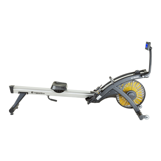
- Page 1 USER MANUAL – EN IN 16384 Rowing Machine inSPORTline Air Master...
-
Page 2: Table Of Contents
CONTENTS SAFETY PRECAUTIONS ........................3 SPECIFICATIONS ........................... 4 ASSEMBLY ............................. 4 Before you start ............................ 4 Parts list ............................... 5 Tools ..............................6 Assembly steps ............................ 7 FEATURES............................15 Adjusting the foot rest ........................15 Hook for the pulling handle ........................ 16 Adjusting the console position ...................... -
Page 3: Safety Precautions
SAFETY PRECAUTIONS BEFORE BEGINNING ASSEMBLY, READ THE INSTRUCTION MANUAL FIRST. WE’VE PREPARED THE INSTRUCTIONS WITH CARE AND FOLLOWING THEM WILL MAKE THE ASSEMBLY EASIER FOR YOU, AS WELL AS MINIMISE THE RISK OF AN INJURY. KEEP THESE INSTRUCTIONS FOR FUTURE REFERENCE. THIS PRECAUTION LIST IS NOT DEFINITIVE. -
Page 4: Specifications
• Parents and other adults in charge of children are responsible for keeping the children in their care from playing on the rowing machine. The product should under no circumstances be used as a children’s toy. • If you allow children to use this machine, their mental and physical development, as well as their temperament, should be taken into account. -
Page 5: Parts List
Parts list A. Main Frame B. Front Stabilizer (1 pc) C. Rear Stabilizer (1 pc) D. Seat (1 pc) E. Track (1 pc) -
Page 6: Tools
F. Foot Rest (1 pc) G. Rear Handle (1 pc) Power adapter (1 pc) Tools • Allen Key (6 and 5 mm) -
Page 7: Assembly Steps
Assembly steps LOCATE THE HANDLEBAR • Place the handlebar against the hooks, as shown in the picture. • Pull out the Stop Pin attached to the pulling strap and carefully remove the strap stopper. • The stopper is there for transporting purposes and won’t be needed again. All bolts and washers had been pre-assembled to make the assembly easier. - Page 8 ATTACH THE FRONT STABILIZER 1. Remove the cardboard tube from the front-end stabilizer bracket. • Loosen the two M8 x 16 Allen Head Bolts in the cardboard tube and remove the tube. • The two Allen Head Bolts and the cardboard tube are there for transporting purposes and won’t be needed again during the assembly.
- Page 9 Connecting material Tools B5 (4 pcs) B6 (4 pcs) 6 mm Make sure you connect the parts in the same order as shown on the picture. Make sure the bolts are tightened fully. Make sure the wheels on the front stabilizer face outwards. ATTACH THE FOOT REST ASSEMBLY 1.
- Page 10 • Insert the Foot Rest Assembly and attach it onto the Main Frame Mounting Bracket carefully with four M8 x 30 mm Hex Socket Head Bolts (B8) and M8 x 16 mm x 1.5 mm Flat Washers (B7), then tighten the bolts with the 6-mm Allen Key. Connecting material Tools B8 (4 pcs)
- Page 11 ATTACH THE REAR STABILIZER AND THE REAR HANDLE 1. Attach the rear stabilizer. • Remove the four M8 x 20 mm Hex Socket Head Bolts (B5) and M8 x 16 mm x 1.5 mm Flat Washers (B7) from both sides of the rear end of the Track with the 6-mm Allen Key. •...
- Page 12 • Cut off the line that secures the Seat Carriage Assembly to the front end of the Track. Connections Tools B9 (4 pcs) 5 mm Make sure you connect the parts in the same order as shown on the picture. Make sure the bolts are tightened fully.
- Page 13 ATTACH THE TRACK ASSEMBLY • Hold the Track Assembly and carefully slide it onto the mounting tube of the main frame. • Use your hands to carefully tighten two M8 x 16 mm Hex Socket Head Bolt (B5) and M8 x 16 mm x 1.5 mm Flat Washers (B7) on the bottom of the Track.
- Page 14 ATTACH THE SEAT • Remove the four M8 x 16 mm Hex Socket Head Bolts (B5) from the underside of the seat with the 6-mm Allen Key, as shown in the picture. • Attach the Seat to the Seat Carriage Assembly with four M8 x 16 mm Hex Socket Head Bolts (B5).
-
Page 15: Features
POWER UP • Connect the power cord to the rowing machine, as shown in the picture. • Plug the other end of the power cord into a suitable AC outlet (110 or 220~240V / 50 Hz) FINAL CHECKS Your rowing machine is now assembled. Before first use, follow the following steps. •... -
Page 16: Hook For The Pulling Handle
Hook for the pulling handle Before you start your workout, place the pulling handle in the Handle Hook to make it easier to reach when you are seated. -
Page 17: Adjusting The Console Position
Adjusting the console position Adjust the console arm and display to a position that suits you best, as shown in the picture. Resistance adjustment 1. The rowing machine features a speed-dependent braking system. 2. The harder you pull, the more resistance you will experience. If you put more effort into the rowing movement, you will go faster, produce more watts and burn more calories. -
Page 18: Levelling
Levelling 1. There are two adjustable footpads to level the rowing machine on an uneven surface. 2. Simply turn them to adjust the height of the rowing machine and secure the locked handles to the rear stabilizer as required. Transport 1. -
Page 19: How To Fold The Rowing Machine
HOW TO FOLD THE ROWING MACHINE Folding Fold the console and the console arm as shown in the picture. Move the seat to the front. Hold the rear end of the seat track with your right hand. Use the left hand to firmly grasp the handle, as shown in the picture. -
Page 20: Unfolding
Unfolding Stand behind the rowing machine and hold the handle with your left hand, as shown in the picture. Use your right foot to stop the front stabilizer while you carefully lower the rowing machine. Hold the rear end of the seat track with your right hand and continue to hold the handle with your left. -
Page 21: Computer Instructions
COMPUTER INSTRUCTIONS Quick Start Use this mode if you want a quick workout session and are not interested in setting up your personal data. • Row for a few seconds to power on the console. • “MAINPAGE” will be shown on the display. •... -
Page 22: Display And Feedback
• Use this button to select a pre-set program in the standby mode (MANUAL > RACE > PROFILE > WATT > H.R.C. > USER 1 – USER 5). • Use this button to increase the value while you are setting a value target. If you want the value change more quickly, hold the button. -
Page 23: Programs
Displays the power generated by your movement. (This function serves only as an indication, it is not suitable for medical purposes.) The display range is 0-999 W. If a target value has been set, the value is counted down in the range of 10-995 W. Displays the number of strokes during a rowing session in the range of 0- 9999 strokes. - Page 24 4. “--:--” will start flashing in the TIME window. 5. Use to arrow buttons to set a target value. The default value is 20:00. The settings range is 5:00-99:00 minutes. 6. Press “ENTER” to confirm your setting and to set the resistance level. 7.
- Page 25 NOTE: Each of the pre-set programs is made up of 16 segments. The length if each segment depends on the time set for your rowing session. If the total workout time is 32 minutes, you will have 2 minutes per segment. The end of each segment and a beginning of new one is denoted with a chime.
- Page 26 11. Press “START” to begin the workout and then start rowing. The program will not start until you begin rowing. NOTE: You can press “STOP” to end the program at any point. A workout summary will be displayed on the screen. NOTE: You can change the resistance level (1-16) at any point with the arrow buttons.
- Page 27 5. Use the arrow buttons to set a target value. The default value is 150. The settings range is 50- 9990 cal. 6. Press “ENTER” to confirm your setting and set the resistance level. 7. The default value of “5” will start flashing in the “LEVEL” window. 8.
- Page 28 4. “-----” will start flashing in the METERS window. 5. Use to arrow buttons to set a target value. The default value is 1000 meters. The settings range is 500-99900 meters. 6. Press “ENTER” to confirm your setting and set the resistance level. 7.
- Page 29 NOTE: Each of the pre-set programs is made up of 16 segments. The total distance will be evenly divided into 16 parts. If the total distance is 800 m, there will be 50 meters per segment and the time of each segment will change according to the resistance setting. The end of each segment and a beginning of new one is denoted with a chime.
- Page 30 12. Press “ENTER” to confirm your setting. 13. “START” will start flashing at the bottom of the display. 14. Press “START” to begin the workout and then start rowing. The program will not start until you begin rowing. NOTE: You can press “STOP” to end the program at any point. A workout summary will be displayed on the screen.
- Page 31 NOTE: HW – under 75 kg (165 lb) / LW – over 75 kg (165 lb) PRE-SET PROGRAMS This feature allows you to choose from 12 programs with pre-set resistance profiles. The resistance adjusts automatically throughout the program. You can set a target time, strokes per minute, burned calories and distance travelled.
- Page 32 4. “P1” will appear at the bottom of the screen and the program profile will be displayed. 5. Use the arrow buttons to select the program you want (P1-P12). 6. Press “ENTER” to confirm your selection. 7. “--:--” will start flashing in the TIME window. 8.
- Page 33 19. “LEVEL +/-” will start flashing at the bottom of the display. 20. Use the arrow buttons to adjust the program profile if needed. 21. Press “ENTER” to confirm your setting. “START” will start flashing at the bottom of the display. 22.
- Page 34 2. Use the arrow buttons to select “WATT”. 3. Press “ENTER” to confirm your selection. 4. The default value of “50” will start flashing in the WATTS window. 5. Use the arrow buttons to adjust the setting. The settings range is 10-995 W. 6.
- Page 35 21. Press “ENTER” to confirm your setting. 22. “START” will start flashing at the bottom of the display. 23. Press “START” to begin the workout and then start rowing. The program will not start until you begin rowing. NOTE: You can change the target watts value at any point during your workout by using the arrow buttons.
- Page 36 HRC (HEART RATE CONTROL) HRC programs automatically adjust your resistance to keep your heart rate in the target zone. To do this, the console needs to be able to receive your heart rate data throughout your workout. You’ll need a chest strap with a 5.4 kHz transmitter (Polar 5.4 kHz chest strap is recommended). The HRC program will not work with hand heart rate detectors.
- Page 37 8. The selection of programs will be displayed at the bottom of the screen (55% > 75% > 85% > THR). 9. If required, use the arrow buttons to adjust your target heart rate. Settings rage is 40-220 bpm. 10. Press “ENTER” to confirm your setting. 11.
- Page 38 If the console doesn’t receive heart rate signal, “NO PULSE” will appear at the bottom of the display. NOTE: You can press “STOP” to end the program at any point. A workout summary will be displayed on the screen. NOTE: You can ignore any program “target settings” if you are not interested in them. You can only set one of the targets described above.
- Page 39 8. Use the arrow buttons to set the value. The default value is 20:00 min. The settings range is 5:00-99:00 min. 9. Press “START” to begin your workout or press “ENTER” to set target number of strokes. 10. “----” will start flashing in the STROKES window. 11.
- Page 40 22. Press “START” to begin the workout and then start rowing. The program will not start until you begin rowing. When setting a personal training program for the first time… 6. Press and hold “ENTER” to start your personal workout profile setting. 7.
- Page 41 14. Use the arrow buttons to set the value. The default value is 20:00 min. The settings range is 5:00-99:00 min. 15. Press “START” to begin your workout or press “ENTER” to set target number of strokes. 16. “----” will start flashing in the STROKES window. 17.
-
Page 42: Care And Maintenance
NOTE: Each program is made up of 16 segments. The target time, number of strokes, burned calories and distance will be evenly divided into 16 parts. The time of each segment will change according to the resistance setting. The end of each segment and a beginning of new one is denoted with a chime. -
Page 43: Troubleshooting
• Check if the foot strap is tightly secured by the buckle. • Check if the foot pad self-locking mechanism is working correctly or not. • Make sure that all the nuts and bolts are tightly secured. • Use a warm, damp cloth to clean the foot pads. Use a mild detergent if necessary. Check and replace the AA battery in the control panel –... - Page 44 • Start each workout with several minutes of easy rowing as a warm-up. Take at least 5 minutes to build up the intensity before starting a proper workout. If you haven’t rowed in over a week, take it easy at first. •...
-
Page 45: Fitness
End position Your back should be leaned lightly backwards (around 25 degrees), your legs fully extended. should feel comfortable in this position, not strained. When you reach this position, you should feel your abdominal muscles working. Return Extend your arms towards the fan. Lean your upper body forward at the hips. -
Page 46: How To Improve Your Fitness
When you are fit, your heart and lungs work well and efficiently. This means your heart will not have to develop too much effort. It will pump fewer times per minute, reducing the wear rate of the tissue. It reduces your chances of suffering heart disease. Fitness training also helps you control your weight and reduces the effects of aging and stress. -
Page 47: Heart Rate Training
Heart rate (bpm) Age (years) Find your own heart rate range by finding your age and moving up the vertical line. Example: At age 40, the vertical line meets the 70% heart rate at about 128 bpm and the 85% heart rate at 154 bpm. Your heart rate should remain between these values. - Page 48 To calculate your target heart rate, simply multiply your maximum heart rate by the required percentage. So, if your goal is better health, the calculations will look like this: 185 x 60% (0.60) = 111 bpm NOTE: The important issue to remember with all estimated calculation is that they are just that –...
-
Page 49: Exploded View
EXPLODED VIEW... -
Page 50: Parts List
PARTS LIST ITEM DESCRIPTION Q'TY ITEM DESCRIPTION Q'TY Main Frame M8*16*1.5mm Flat Washer Handlebar Holder Socket Head Bolt (M8*30mm) Metal Top Cover Socket Head Bolt (M8*16mm) Pulling Strap Top Cover B-10 Socket Head Bolt (M8*12mm) Main Cover (L) B-11 Self-Tapping Screw M4*12.7 Main Cover (P) B-12 Cap Nut (M6) - Page 51 A-24 Wave Washer Phillip Head Machine Screw M5*10mm Metal Bushing ɸ4xɸ(6+12) x A-24.4 Footrest Plate (3.3+1.5)L A-25 C Clip - S12 Footrest Pad (R) A-26 Nut 3"26 8T Footrest Pad (L) A-27 Magnet Resistance Set Pedal-Adjusting Lever A-27.1 Magnetic Pad Pedal Securing Key A-27.2 Magnet...
-
Page 52: Console Assembly
Foot Stop Self-Tapping Screw M4*12 Stabilizer End Cap 3" Nylon Cap Nut M8 Transport Wheel I-10 Socket Head Bolt (M8*85mm) Socket Head Bolt I-11 Self-Tapping Screw M4*12 (M8*16mm) Curve Washer Ribbed Belt - 370 J8 CONSOLE ASSEMBLY... -
Page 53: Terms And Conditions Of Warranty, Warranty Claims
Console Connecting H.R. Rec Connecting Cable Hear rate receiver Cable (3 PIN + (3 PIN + 900mm) 750mm) TERMS AND CONDITIONS OF WARRANTY, WARRANTY CLAIMS General Conditions of Warranty and Definition of Terms All Warranty Conditions stated hereunder determine Warranty Coverage and Warranty Claim Procedure. - Page 54 “The Buyer who is not the End Customer” is a Businessman that buys Goods or uses services for the purpose of using the Goods or services for his own business activities. The Buyer conforms to the General Purchase Agreement and business conditions to the extent specified in the Commercial Code.
- Page 55 VAT ID: CZ26847264 Phone: +420 556 300 970 E-mail: eshop@insportline.cz reklamace@insportline.cz servis@insportline.cz Web: www.insportline.cz INSPORTLINE s.r.o. Headquarters, Warranty & Service centre: Elektricna 6471, 911 01 Trencin, Slovakia CRN: 36311723 VAT ID: SK2020177082 Phone: +421(0)326 526 701 E-mail: objednavky@insportline.sk reklamacie@insportline.sk servis@insportline.sk Web: www.insportline.sk...
Need help?
Do you have a question about the IN 16384 and is the answer not in the manual?
Questions and answers