Advertisement
Quick Links
Advertisement

Related Manuals for Insportline IN 724


Summary of Contents for Insportline IN 724
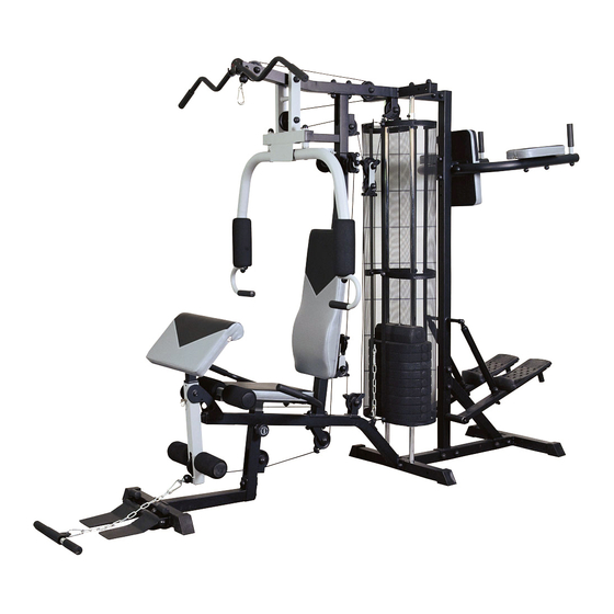
- Page 1 USER MANUAL - EN IN 724 Multifunction trainer inSPORTline Athlet...
-
Page 2: Table Of Contents
Part list description specification q'ty Base frame Rear stabilizer Front vertical support Upper beam Front stabilizer Seat support Right butterfly arm Left butterfly arm Butterfly arm support Foot plate fixing beam Leg curler Upper pulling bar Lower pulling bar Foam roller Weight guidance rod Weight protector 1450*502*1.0T... - Page 3 Square plastic cap 25*50*14 Round plastic cap D25.4*D65*31L Buffer R23*35*35 Round buffer D60xD26x26T Fixing sleeve D31.8*1.5T*30 Cable guidance D16.5*80.5*24*32 Plastic ring for cable guidance D16*D10.5*5.5T foam D47*D90*250L foam D23*D90*165L foam D25.4*3.5*118L Upper weight plate 280x100x80 Lower weight plate 370*200*42 backrest 695*280*50 seat 350*260*305*50T...
- Page 4 arm support arm pad 280*165*50T hand grip Back pad 380*250*50T reiforcing tube left pedal support right pedal support cylinder D38*432L pedal 340*170*72 buffer D33*D44*41.5 round cap D50.8x16L square end cap 30*60*17...
- Page 5 CHECK LIST IN PACKAGE:...
- Page 6 SCREW LIST:...
-
Page 7: Rear Stabilizer
INSTRUCTION ASSEMBLY: STEP 1. FIG1 (1) Fix the rear stabilizer(2) and 2 weight guidance rods(16) by using 2 flat washers(101), 2 bolts(115) and 2 foot caps(32). (2) Fix the rear stabilizer and base frame(1) by using reinforcing board(62),flat washer(101),nylon nut(102) and bolts(104). (3) Fix the foot plate fixing beam (10) and front stabilizer(5) by using reinforcing board(62),flat washer(101),nylon nut(102) and bolts(104), and then assemble the foot cap(32)and round plastic cap(33) to the foot plate fixing beam(10). -
Page 8: Front Vertical Support
STEP 2. FIG2 (1) Fix the front vertical support(3), base frame(1) and hooking plate(21) by using 2 nylon nuts(102), 4 flat washers(101),and 2 bolts(104). (2) Assemble the cross plate (27), 2 round buffers(39) from the bottom , then assemble 12 lower weight plates(47) and 1 upper weight plate(46) through the weight guidance rod(16). -
Page 9: Upper Beam
STEP 3 FIG3 (1) Assemble the upper beam(4) onto the front support(31), weight guidance rod by using 3 square plastic caps(35), then sequentially with 2 bolts(104), 4 flat washers(101), 1 reinforcing board, 2 nylon nut(102); 2 bolts(115), 2 flat washers(101), and then fix the rubber buffer onto the front vertical support(3). (2) Fix the support of single pulley support(69) to the front vertical support by using 1 bolt(114),2 flat washers(101) and 1 nylon nut(102). - Page 10 STEP 4 FIG4 (1) Fix the butterfly arm support (9) to the upper beam(4) by using 1 bolt(113), 2 flat washers(106), 1 nylon nut (107) and 2 bushings(31). (2) Insert axle for foot plate(60) into foot plate, and then assemble the foot plate to the foot plate beam(10) by using 2 bolts(115), 2 flat washers(101).
- Page 11 STEP 5 (1) Assemble the right & left butterfly arm (7) & (8) onto the butterfly arm support (9) by using 2 nylon nuts (102), 1 flat washer (101) . (2) Slide the foam (43) onto the butterfly arm ,then assemble the butterfly hand grip(70) to the butterfly arm by using 1 flat washer(101),1 bolt(104).
- Page 12 STEP 6 FIG6 (1) fix the leg curler(11) onto the base frame by using 2 bushings(31), flat washer(101), 1 flat washer(106), 1 nylon nut(102) and 1 bolt(111) ,and then fix the square plastic cap (35) into the leg curler(11). (2) Turn the rubber buffer (61) into the main frame (1). (3) Fix the arm curl pad (66) to the plate of arm curl support (67) by meanings of 2 flat washer (117) and 2 bolt (116).
-
Page 13: Seat Support
STEP 7 FIG7 (1) fix the hand grip(68) under to the seat support (6) with 2 bolt (100) , 4 flat washer (101). And then also assembly the seat (49) onto the seat support (6) by 2 bolt (109) and 2 flat washer (101). -
Page 14: Right Butterfly Arm
STEP 8 FIG8 Connection of cable (butterfly arm)(51) and assembly the pulley: (1) hooking one end of the cable to the right butterfly arm (7) and slide the other end of the cable along the pulley, at the same time you need to fix the 1 raised pulley (56) into the 1 single pulley support (20) by 2 plastic ring (42), 2 cable guidance (41), 2 flat washer (101), 1 bolt (112) and 1 nut (102). -
Page 15: Butterfly Arm Support
STEP 9 FIG9 Connection the cable (50) and at the same time the flat pulley (57) and raised pulley (56): 1. the cable going way as drawing . From one end of cable to the other, you need to fix the raised pulley (56) and flat pulley (57). -
Page 16: Leg Curler
STEP 10 FIG10 Assembly the cable (52, leg curler) and pulley at the same time: 1. the cable going way as drawing . From one end of cable to the other, there will be 5 raised pulley (56) among these 2 already assembled in step 8 & 9 when fix the cable (50) &(51) and 1 flat pulley (57). -
Page 17: Weight Protector
STEP 11 FIG11 (1) Fix the cover fixing plate with rod (28) and cover fixing plate (29) Around the weight protector (17) by using bolt (116), flat washer(117) And nut (118). Please note the correct assembly way of cover fixing plate with rod (28), on the upper, the rod upwards and on the lower, the rod downwards which will connect with the cross plate (27). - Page 18 STEP 12 FIG12 1. connect the rear vertical tube (79) with the base frame (1) and rear stabilizer (78) by using 2 bolt (100), 4 flat washer (101), 2 nut (102). Then connect the rear vertical tube with the upper beam by 2 bolt (103), 4 flat washer (101) and 2 nut (102).
- Page 19 STEP 13 FIG13 1. attach the reinforce press tube (84) with rear vertical tube (79) and rear stabilizer (78) using 4 bolt (100), 8 flat washer (101),and 4 nut (102). 2. assembly the arm tube welding set (80) attach to the rear vertical tube (79) using 2 bolt (100), 4 flat washer (101), 2 nut (102).
- Page 20 STEP 14 FIG14 1. fix 2 pedal (87) onto the pedal support (85L & 85R) using 4 bolt (123), 4 flat washer (117) and 4 nut (118). 2. assembly the hydraulic cylinder (86) with the pedal support and rear vertical tube using 1 bolt (121), 1 spring washer (124), 1 flat washer (125) and 1 T knob, 1 flat washer .
- Page 21 STEP 15 FIG15 Finally, please cover the screw cap M6 (74), M8(75), M10(76) and M12(77) onto the bolts and screws.
- Page 22 EXERCISE PICTURES:...