Advertisement
Table of Contents
Advertisement
Table of Contents

Subscribe to Our Youtube Channel
Related Manuals for Insportline IN465


Summary of Contents for Insportline IN465
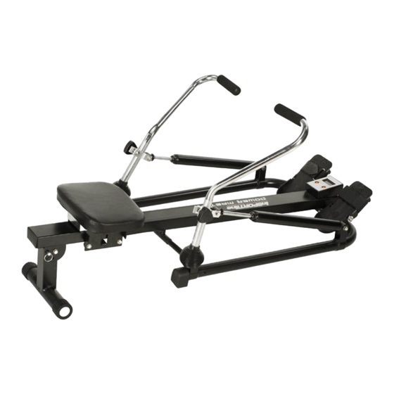
- Page 1 User’s manual –ENG IN465 ROWER POWER MASTER Safety Instructions...
- Page 2 • To ensure the best safety of the exerciser, regularly check it on damages and worn parts. • When setting up the exerciser, please make sure that the exerciser is standing in a stable way and that any possible unevenness of the •...
-
Page 3: Important Notes
Important Notes • Assemble the exerciser as per assembly instructions and be sure to only use the structural parts provided with the exerciser and designed for it. Prior to the assembly, make sure the content of the delivery is complete by referring to the parts list of the assembly and operating instructions. -
Page 4: Exploded Drawing
Exploded Drawing 21 10... -
Page 5: Part List
Part List part no. description q'ty part no. description q'ty slide rail left handlebar seat right handlebar seat bracket piston cross bolt carriage bolt cross screw computer fixing plate small foot cap foam square plug for slide rail foot cap adjustable bracket foot cap computer... - Page 6 Assembly : Step 1 Fix the square plug (7) onto both end of slide rail (1), foot cap (29) and (30) onto left supporting frame (19) and right supporting frame (20) STEP-1 Step 2 Fix seat (2) onto slide rail (1) by seat bracket (3) and bolt (4); Fix the adjustable bracket (8) with rail and stabilizer (15) by using flat washer (10), bolt (21), pin(12),nut(14) and bolt (11)
- Page 7 STEP-2 (x1) M8*1.25*70L D19 D19 M8 (x4) M8*15L (x4) M6*16L Step 3 Fix the connecting axle (17) with left & right supporting frame (19&20), slide rail (1) by using flat washer (10), bolt (21) & bolt (18). Fix the left & right supporting frame (19&20) with slide rail (1) by flat washer (10),bolt (26),nut(14) Fix the small foot cap (6) with screw (5) 10 21...
- Page 8 Fix the left & right handlebar (23 &24), piston(25) and plastic cover (22) with left & right supporting frame (19&20) by H hook (34), knob(31),bolt (33), flat washer (10), nut (14) 14 10 (x2) M8*1.25*50L STEP-4 D19 D19 M8 (x4) M8*1.25*40L D19 D19 M8 Step 5...
-
Page 9: Function: Time
INSTRUCTION MANUAL OF COMPUTER LT-8120 TIME………………….00:00-99:59MIN PULSE*(IF HAVE)…………0-192T/M SPEED…………0.0-99.9KM/H or ML/H CALORIES…………………0-9999KCAL DISTANCE……….0.000-999.9KM or ML SELECT: This key lets you to select and lock on to particular function you want. RESET: The key reset the value to zero by pressing the key. OPERATION PROCEDURES: 1. - Page 10 Press the SELECT key once to lock on the TIME function. the colon Stop blinking, SPEED Press the SELECT key until the pointer advance to SPEED and blinking. Press to SELECT key once the pointer should stop blinking and lock on To the SPEED function, DISTANCE Press the SELECT key until the pointer advances to DSTANCE and blinking.
Need help?
Do you have a question about the IN465 and is the answer not in the manual?
Questions and answers