Sign In
Upload
Download
Table of Contents
Contents
Add to my manuals
Delete from my manuals
Share
URL of this page:
HTML Link:
Bookmark this page
Add
Manual will be automatically added to "My Manuals"
Print this page
×
Bookmark added
×
Added to my manuals
Manuals
Brands
Insportline Manuals
Home Gym
IN 14953
User manual
Insportline IN 14953 User Manual
Hide thumbs
1
Table Of Contents
2
3
4
5
6
7
8
9
10
11
12
13
14
15
16
17
18
19
20
21
page
of
21
Go
/
21
Contents
Table of Contents
Bookmarks
Table of Contents
Table of Contents
Safety Precautions
Parameters
Parts List
Assembly
Pedal Adjustment
Adjusting Downwards
Control Panel
Display Functions
Key Functions
Operations
Program Resistance Profiles
Chest Strap Instructions
Battery Installation
Put the Chest Strap on
Notifications
Exploded Drawing
Parts List
Terms and Conditions of Warranty, Warranty Claims
Advertisement
Quick Links
Download this manual
USER MANUAL – EN
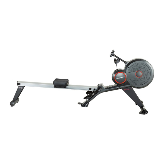
IN 14953 Rowing Machine inSPORTline Rivu
Table of
Contents
Previous
Page
Next
Page
1
2
3
4
5
Advertisement
Table of Contents
Need help?
Do you have a question about the IN 14953 and is the answer not in the manual?
Ask a question
Questions and answers
Related Manuals for Insportline IN 14953
Home Gym Insportline IN 1979 Ocean User Manual
(11 pages)
Home Gym Insportline IN 1920 User Manual
Air magnetic rower insportline river (44 pages)
Home Gym Insportline IN 16384 User Manual
(55 pages)
Home Gym Insportline IN 16143 User Manual
Rowing machine insportline kobuko (17 pages)
Home Gym Insportline IN 16443 User Manual
(27 pages)
Home Gym Insportline Ocean IN 1979 Manual
(11 pages)
Home Gym Insportline Profi Sit Up IN 1227 User Manual
Multi-purpose bench (8 pages)
Home Gym Insportline Brook IN 14348 User Manual
(12 pages)
Home Gym Insportline IN465 User Manual
Insportline rower power master user's manual (10 pages)
Home Gym Insportline IN 2812 User Manual
Rowing machine amazonian (15 pages)
Home Gym Insportline IN 2812 User Manual
Rowing machine insportline amazonian (16 pages)
Home Gym Insportline IN 4069 User Manual
Multi-function bench (13 pages)
Home Gym Insportline IN 5564 User Manual
Air magnetic rower (27 pages)
Home Gym inSPORTline IN 724 User Manual
Multifunction trainer insportline athlet (24 pages)
Home Gym Insportline IN 8722 User Manual
(23 pages)
Home Gym Insportline IN 26050 User Manual
(15 pages)
This manual is also suitable for:
Rivu
Table of Contents
Print
Rename the bookmark
Delete bookmark?
Delete from my manuals?
Login
Sign In
OR
Sign in with Facebook
Sign in with Google
Upload manual
Upload from disk
Upload from URL


Need help?
Do you have a question about the IN 14953 and is the answer not in the manual?
Questions and answers