Table of Contents
Advertisement
INSTALLATION AND OPERATION MANUAL
CWGE24MS2
COMMERCIAL GRADE MANAGED LAYER 2+ ETHERNET SWITCH
WITH 20 × 100/1000BASE-FX + 4 × GIGABIT COMBO PORTS
v1.0 November 29, 2016
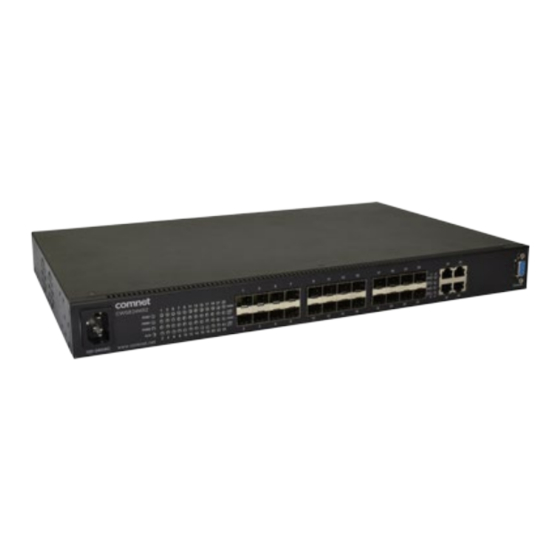
The ComNet CWGE24MS2 has twenty 100/1000Base-FX SFP ports and four Gigabit
combo ports that allow for TX or FX transmission. All SFP ports utilize ComNet SFP
modules for fiber, connector type and distance. The IEEE802.3-compliant unit offers
multiple Ethernet redundancy protocols (ERPS G.8032 and MSTP/RSTP/STP) which
protect your applications from network interruptions or temporary malfunctions by
redirecting transmission within the network. The CWGE24MS2 implements complete
Layer 2 to Layer 4 ACLs to restrict access to your sensitive network resources by filtering
specific packets based on TCP/UDP ports, source and destination IP addresses or
particular network devices. Furthermore, DHCP snooping, TACACS+, ARP, IEEE 802.1X
and Port Security provide additional tools to manage access and levels of use of the
network. These defence mechanisms of the CWGE24MS2 along with advanced DoS
auto prevention deliver robust network security and enables network administrators
to offer more stable services on a more secure network.
Advertisement
Table of Contents

Related Manuals for Comnet CWGE24MS2


 Series Installation And Operation Manual](https://static-data2.manualslib.com/product-images/ee5/992441/60x60/comnet-clfe4-1sms-poe-c-u-series-network-router.jpg)


Summary of Contents for Comnet CWGE24MS2
- Page 1 November 29, 2016 The ComNet CWGE24MS2 has twenty 100/1000Base-FX SFP ports and four Gigabit combo ports that allow for TX or FX transmission. All SFP ports utilize ComNet SFP modules for fiber, connector type and distance. The IEEE802.3-compliant unit offers multiple Ethernet redundancy protocols (ERPS G.8032 and MSTP/RSTP/STP) which...
-
Page 2: Table Of Contents
INSTALLATION AND OPERATION MANUAL CWGE24MS2 Contents Regulatory Compliance Statement Warranty Disclaimer Safety Indications Copyright FCC Warning Overview Introduction Software Features Hardware Features Hardware Overview Front Panel Installation Desktop Installation Mounting on a Rack Getting Connected Powering On the Unit Installing the SFP modules and Fiber Cable... - Page 3 INSTALLATION AND OPERATION MANUAL CWGE24MS2 Advanced Settings Bandwidth Control DHCPv6 IGMP Snooping VLAN DHCP Option Dual Homing ERPS Link Aggregation Link Layer Discovery Protocol (LLDP) Loop Detection PPPoE IA Static Route UDLD Security IP Source Guard 802.1x Port Security TACACS+...
- Page 4 INSTALLATION AND OPERATION MANUAL CWGE24MS2 Management SNMP Auto Provision Mail Alarm Maintenance System log User Account INS_CWGE24MS2_REV– TECH SUPPORT: 1.888.678.9427 10/05/16 PAGE 4...
-
Page 5: Regulatory Compliance Statement
Disclaimer Information in this publication is intended to be accurate. ComNet shall not be responsible for its use or infringements on third-parties as a result of its use. There may occasionally be unintentional errors on this publication. ComNet reserves the right to revise the contents of this publication without notice. -
Page 6: Fcc Warning
INSTALLATION AND OPERATION MANUAL CWGE24MS2 FCC Warning This equipment has been tested and found to comply with the limits for a class A device, pursuant to part 15 of FCC rules. These limits are designed to provide reasonable protection against harmful interference in a commercial installation. -
Page 7: Overview
The ComNet CWGE24MS2 has twenty 100/1000Base-FX SFP ports and four Gigabit combo ports that allow for TX or FX transmission. All SFP ports utilize ComNet SFP modules for fiber, connector type and distance. The IEEE802.3-compliant unit offers multiple Ethernet redundancy protocols (ERPS G.8032 and MSTP/RSTP/STP) which protect your applications from network... -
Page 8: Software Features
INSTALLATION AND OPERATION MANUAL CWGE24MS2 Software Features Network Functions » Port-based Mirroring » GARP/GVRP Support » 4K Active VLAN » IGMP Snooping v1/v2/v3 » IGMP Querier » MVR » DHCP Relay/Option 82 » Dual Homing » Link Aggregation » Link Layer Discovery Protocol »... - Page 9 INSTALLATION AND OPERATION MANUAL CWGE24MS2 Network Management » Command Line Interface, Telnet » Web GUI » SNMP v1/v2c/v3 » Management VLAN » Auto Provisioning » System log » Firmware Upgradable » Configuration Upload/Download » LED, SNMP trap, and email alarm Specifications »...
-
Page 10: Hardware Features
INSTALLATION AND OPERATION MANUAL CWGE24MS2 Hardware Features Performance » Switching fabric 48 Gbps » L2 forwarding 35.7 Mpps » MAC Entries 16 K » Jumbo frame 10 K Ports » 20-slot 100FX/Gigabit SFP » 4 × Gigabit Combo (10/100/1000 RJ-45 or 100FX/GbE SFP) »... -
Page 11: Hardware Overview
INSTALLATION AND OPERATION MANUAL CWGE24MS2 Hardware Overview Front Panel The following table describes the labels that are affixed to the CWGE24MS. Port Description SFP ports 20 × 100BaseX Giga Ethernet Port 4 × Gigabit Combo (10/100/1000 RJ-45 or 100FX/GbE SFP) Console Use RS-232 with DB9 connecter to manage switch. - Page 12 100Mbps/Gigabit SFP modules. Gigabit Combo There are four Gigabit Combo ports on the CWGE24MS2. Combo ports have both an RJ-45 interface and an SFP slot, of which one can be in use at any one time. The RJ-45 ports operate at 10/100/1000 Mbps, while the SFP ports are capable of operating at 100Mbps or 1000 Mbps.
-
Page 13: Installation
INSTALLATION AND OPERATION MANUAL CWGE24MS2 Installation The location chosen for installing the Switch may affect its performance. When selecting a site, we recommend considering the following rules: Install the Switch in an appropriate place. See Technical Specifications for the acceptable temperature and humidity ranges. -
Page 14: Installing The Sfp Modules And Fiber Cable
INSTALLATION AND OPERATION MANUAL CWGE24MS2 The Switch uses an AC power supply 100~240VAC, 50~60 Hz. The Switch’s power supply automatically self-adjusts to the local power source and may be powered on without having any or all LAN segment cables connected. -
Page 15: Connecting To The Console
INSTALLATION AND OPERATION MANUAL CWGE24MS2 The RJ-45 Ethernet port fully supports auto-sensing and auto-negotiation. » Insert one end of a Category 3/4/5/5e (see recommendation above) type twisted-pair cable into an available RJ-45 port on the Switch and the other end into the port of the network node. -
Page 16: Led Indicators
INSTALLATION AND OPERATION MANUAL CWGE24MS2 LED Indicators This Switch is equipped with Unit LEDs to enable you to determine the status of the Switch, as well as Port LEDs to display what is happening in all your connections. They are as follows:... - Page 17 INSTALLATION AND OPERATION MANUAL CWGE24MS2 Management Options This system may be managed out-of-band through the console port on the front panel or in-band by using Telnet. The user may also choose web-based management, accessible through a Web browser. Web-based Management Interface After you have successfully installed the Switch, you can configure the Switch, monitor the LED panel, and display statistics graphically using a Web browser.
- Page 18 INSTALLATION AND OPERATION MANUAL CWGE24MS2 Note: Ensure that the terminal or PC you are using to make this connection is configured to match the above settings. Otherwise the connection will not work. Then press [ENTER] to open the login screen with the “Default Value” for Username and Password as “admin”.
- Page 19 Please press Enter to activate this console Input “admin” to enter the CLI mode when below message is displayed on the screen. CWGE24MS2 login: You can execute a few limited commands when CLI prompt is displayed as below. CWGE24MS2>...
- Page 20 INSTALLATION AND OPERATION MANUAL CWGE24MS2 The Node type: » enable » Its command prompt is “CWGE24MS2#”. » It means these commands can be executed in this command prompt. configure Its command prompt is “CWGE24MS2(config)#”. It means these commands can be executed in this command prompt.
- Page 21 INSTALLATION AND OPERATION MANUAL CWGE24MS2 vlan Its command prompt is “CWGE24MS2(config-vlan)#”. It means these commands can be executed in this command prompt. In Configure code, executing command “vlan 2” enter the vlan 2 node. Note: where the “2” is the vlan ID.
-
Page 22: Gui Login
INSTALLATION AND OPERATION MANUAL CWGE24MS2 GUI Login Parameter Description User ID Enter the user name. Password Enter the password. Default: User name: admin, Password: admin. CLI Configuration Node Command Description enable show hostname This command displays the system’s network name. -
Page 23: System Information
INSTALLATION AND OPERATION MANUAL CWGE24MS2 System Information Parameter Description Model Name This field displays the model name of the Switch. Host name This field displays the name of the Switch. Boot Code Version This field displays the boot code version. - Page 24 INSTALLATION AND OPERATION MANUAL CWGE24MS2 Parameter Description Serial Number The serial number assigned by manufacture for identification of the unit. Management VLAN This field displays the VLAN ID that is used for the Switch management purposes. CPU Loading This field displays the percentage of your Switch’s system load.
-
Page 25: Basic Settings
The hostname is same as the SNMP system name. Its length is up to 64 characters. The first 16 characters of the hostname will be configured as the CLI prompt. Default Settings › The default Hostname is CWGE24MS2 › The default DHCP client is disabled. › The default Static IP is 192.168.10.1 ›... - Page 26 INSTALLATION AND OPERATION MANUAL CWGE24MS2 CLI Configuration Node Command Description enable ping IPADDR [–c COUNT] This command sends an echo request to the destination host. The –c parameter allow user to specific the packet count. The default count is 4.
- Page 27 To enter the ETH0 interface node. CWGE24MS2(config)#interface eth0 CWGE24MS2(config-if)# To get an IP address from a DHCP server. CWGE24MS2(config-if)#ip dhcp client enable To configure a static IP address and a gateway for the Switch. CWGE24MS2(config-if)#ip address 192.168.202.111/24 CWGE24MS2(config-if)#ip address default-gateway 192.168.202.1 To configure a static global IPv6 address and a gateway for the Switch.
- Page 28 INSTALLATION AND OPERATION MANUAL CWGE24MS2 Web Configuration Parameter Description IP Address Configures a IPv4 address for your Switch in dotted decimal notation. For example, 192.168.0.254. Subnet Mask Enter the IP subnet mask of your Switch in dotted decimal notation for example 255.255.255.0.
- Page 29 INSTALLATION AND OPERATION MANUAL CWGE24MS2 Jumbo Frame Introduction Jumbo frames are Ethernet frames with a payload greater than 1500 bytes. Jumbo frames can enhance data transmission efficiency in a network. The bigger the frame size, the better the performance. Notice: The jumbo frame settings will apply to all ports.
- Page 30 INSTALLATION AND OPERATION MANUAL CWGE24MS2 Web Configuration Parameter Description Port This field specifies a port or a range of ports for configuration. Frame Size This field configures the maximum number of bytes of frame size for specified port(s). Apply Click this button to take effect the settings.
- Page 31 INSTALLATION AND OPERATION MANUAL CWGE24MS2 SNTP Introduction The Network Time Protocol (NTP) is a protocol for synchronizing the clocks of computer systems over packet-switched, variable-latency data networks. A less complex implementation of NTP, using the same protocol but without requiring the storage of state over extended periods of time is known as the Simple Network Time Protocol (SNTP).
- Page 32 INSTALLATION AND OPERATION MANUAL CWGE24MS2 Default Settings Current Time: ----------------------------------------------- Time: 0:3:51 (UTC) Date: 1970-1-1 Time Server Configuration: ----------------------------------------------- Time Zone : +00:00 IP Address: 0.0.0.0 DayLight Saving Time Configuration: ----------------------------------------------- State : disabled Start Date: None. End Date : None.
- Page 33 INSTALLATION AND OPERATION MANUAL CWGE24MS2 CLI Configuration Node Command Description enable show time This command displays current time and time configurations. configure time Sets the current time on the Switch. HOUR:MINUTE:SECOND hour: 0-23 min: 0-59 sec: 0-59 Note: If you configure Daylight Saving Time after you configure the time, the Switch will apply Daylight Saving Time.
- Page 34 INSTALLATION AND OPERATION MANUAL CWGE24MS2 Example: CWGE24MS2(config)#time ntp-server 192.5.41.41 CWGE24MS2(config)#time timezone +0800 CWGE24MS2(config)#time ntp-server enable CWGE24MS2(config)#time daylight-saving-time start-date first Monday 6 0 CWGE24MS2(config)#time daylight-saving-time end-date last Saturday 10 0 Web Configuration Parameter Description Current Time and Date Current Time This field displays the time you open / refresh this menu.
- Page 35 INSTALLATION AND OPERATION MANUAL CWGE24MS2 Parameter Description Time and Date Setting Manual Select this option if you want to enter the system date and time manually. New Time Enter the new date in year, month and day format and time in hour, minute and second format.
- Page 36 The command displays the all of the interface eth0 configurations. eth0 management host The command adds a management host address. A.B.C.D eth0 no management host The command deletes a management host address. A.B.C.D Example: CWGE24MS2#configure terminal CWGE24MS2(config)#interface eth0 CWGE24MS2(config-if)#management host 192.168.200.106 INS_CWGE24MS2_REV– TECH SUPPORT: 1.888.678.9427 10/05/16 PAGE 36...
- Page 37 INSTALLATION AND OPERATION MANUAL CWGE24MS2 Web Configuration Parameter Description Management Host This field configures the management host. Apply Click this button to take effect the settings. Refresh Click this button to begin configuring this screen afresh. Management Host List This field displays a sequential number for each management host.
-
Page 38: Mac Management
INSTALLATION AND OPERATION MANUAL CWGE24MS2 MAC Management Introduction Dynamic Address: The MAC addresses are learnt by the switch. When the switch receives frames, it will record the source MAC, the received port and the VLAN in the address table with an age time. When the age time is expired, the address entry will be removed from the address table. - Page 39 This command configures the mac table aging time. VALUE configure clear mac address-table This command clears the dynamic address entries. dynamic Example: CWGE24MS2(config)#mac-address-table static 00:11:22:33:44:55 vlan 1 port 1 INS_CWGE24MS2_REV– TECH SUPPORT: 1.888.678.9427 10/05/16 PAGE 39...
- Page 40 INSTALLATION AND OPERATION MANUAL CWGE24MS2 Web Configuration Static MAC A static Media Access Control (MAC) address is an address that has been manually entered in the MAC address table, and do not age out. When you set up static MAC address rules, you are setting static MAC addresses for a port, so this may reduce the need for broadcasting.
- Page 41 INSTALLATION AND OPERATION MANUAL CWGE24MS2 MAC Table Parameter Description Show Type Select All, Static, Dynamic or Port and then click Apply to display the Apply corresponding MAC address entries on this screen. Refresh Click this to update the information in the MAC table.
- Page 42 This command configures a refusal MAC on a specific VLAN. MACADDR vlan VLANID configure mac-address-table refusal This command configures a refusal MAC. MACADDR Example: The procedures to configure a refusal MAC address To enter the configure node. CWGE24MS2#configure terminal INS_CWGE24MS2_REV– TECH SUPPORT: 1.888.678.9427 10/05/16 PAGE 42...
- Page 43 CWGE24MS2 To configure a refusal MAC address for all ports and all vlans. CWGE24MS2(config)#mac-address-table refusal 00:11:22:33:44:55 To configure a refusal MAC address for all ports on a specific vlan. CWGE24MS2(config)#mac-address-table refusal 00:11:22:33:44:55 vlan 1. Web Configuration Parameter Description MAC Address Enter the MAC address of a computer or device that you want to refuse.
- Page 44 INSTALLATION AND OPERATION MANUAL CWGE24MS2 Port Mirror Introduction Port-based Mirroring The Port-Based Mirroring is used on a network switch to send a copy of network packets sent/ received on one or a range of switch ports to a network monitoring connection on another switch port (Monitor to Port).
-
Page 45: Cli Configuration
This command removes a port or a range of ports from the source ports of the port mirroring. Example: CWGE24MS2#configure terminal CWGE24MS2(config)#mirror enable CWGE24MS2(config)#mirror destination port 2 CWGE24MS2(config)#mirror source ports 3-11 mode both INS_CWGE24MS2_REV– TECH SUPPORT: 1.888.678.9427 10/05/16 PAGE 45... - Page 46 INSTALLATION AND OPERATION MANUAL CWGE24MS2 Web Configuration Parameter Description State Select Enable to turn on port mirroring or select Disable to turn it off. Monitor to Port Select the port which connects to a network traffic analyzer. All Ports Settings in this field apply to all ports.
- Page 47 INSTALLATION AND OPERATION MANUAL CWGE24MS2 Port Settings Introduction Duplex mode A duplex communication system is a system composed of two connected parties or devices that can communicate with one another in both directions. Half Duplex: A half-duplex system provides for communication in both directions, but only one direction at a time (not simultaneously).
- Page 48 INSTALLATION AND OPERATION MANUAL CWGE24MS2 For Auto-MDIX to operate correctly, the speed on the interface and duplex setting must be set to “auto”. Auto-MDIX was developed by HP engineers Dan Dove and Bruce Melvin. » Auto Negotiation Auto (auto-negotiation) allows one port to negotiate with a peer port automatically to obtain the connection speed and duplex mode that both ends support.
- Page 49 This command disables the specific ports. if-range no shutdown This command enables the specific ports. if-range speed (auto|10-full||10-half| This command configures the speed and duplex for the 100-full|100-half|1000-full) port. Example: CWGE24MS2#configure terminal CWGE24MS2(config)#interface gi1/0/1 CWGE24MS2(config-if)#speed auto INS_CWGE24MS2_REV– TECH SUPPORT: 1.888.678.9427 10/05/16 PAGE 49...
- Page 50 INSTALLATION AND OPERATION MANUAL CWGE24MS2 Web Configuration INS_CWGE24MS2_REV– TECH SUPPORT: 1.888.678.9427 10/05/16 PAGE 50...
- Page 51 INSTALLATION AND OPERATION MANUAL CWGE24MS2 Parameter Description Port Select a port or a range ports you want to configure on this screen. State Select Enable to activate the port or Disable to deactivate the port. Speed/Duplex Select the speed and duplex mode of the port. The choices are: •...
- Page 52 INSTALLATION AND OPERATION MANUAL CWGE24MS2 Information: Parameter Description Port Select a port or a range ports you want to configure on this screen. Description Configures a meaningful name for the port(s). Port Status Port This field displays the port number.
-
Page 53: Advanced Settings
INSTALLATION AND OPERATION MANUAL CWGE24MS2 Advanced Settings Bandwidth Control Introduction Each egress port can support up to 8 transmit queues. Each egress transmit queue contains a list specifying the packet transmission order. Every incoming frame is forwarded to one of the 8 egress transmit queues of the assigned egress port, based on its priority. - Page 54 INSTALLATION AND OPERATION MANUAL CWGE24MS2 QoS Enhancement You can configure the Switch to prioritize traffic even if the incoming packets are not marked with IEEE 802.1p priority tags or change the existing priority tags based on the criteria you select.
- Page 55 INSTALLATION AND OPERATION MANUAL CWGE24MS2 classes of traffic (voice, video, data, etc.). › Canonical Format Indicator (CFI): a 1-bit field. If the value of this field is 1, the MAC address is in non-canonical format. If the value is 0, the MAC address is in canonical format. It is always set to zero for Ethernet switches.
- Page 56 INSTALLATION AND OPERATION MANUAL CWGE24MS2 DiffServ (DSCP) Differentiated Services or DiffServ is a computer networking architecture that specifies a simple, scalable and coarse-grained mechanism for classifying, managing network traffic and providing Quality of Service (QoS) guarantees on modern IP networks. DiffServ can, for example, be used to...
- Page 57 INSTALLATION AND OPERATION MANUAL CWGE24MS2 +-----+-----+-----+-----+-----+-----+-----+-----+ | PRECEDENCE | D | T | R | 0 | 0 | +-----+-----+-----+-----+-----+-----+-----+-----+ Precedence 111 - Network Control 110 - Internetwork Control 101 - CRITIC/ECP 100 - Flash Override 011 - Flash 010 - Immediate...
- Page 58 INSTALLATION AND OPERATION MANUAL CWGE24MS2 Example: IP Header DSCP=50 => 45 C8 . . . Queuing Algorithms Queuing algorithms allow switches to maintain separate queues for packets from each individual source or flow and prevent a source from monopolizing the bandwidth.
- Page 59 INSTALLATION AND OPERATION MANUAL CWGE24MS2 DSCP Priority DSCP Priority DSCP Priority DSCP Priority ---- -------- ---- -------- ---- -------- ---- -------- Note: If the DiffServ is disabled, the 802.1p tag priority will be used. INS_CWGE24MS2_REV– TECH SUPPORT: 1.888.678.9427 10/05/16 PAGE 59...
- Page 60 INSTALLATION AND OPERATION MANUAL CWGE24MS2 CLI Configuration Node Command Description enable show queue cos-map This command displays the current 802.1p priority mapping to the service queue. enable show qos mode This command displays the current QoS scheduling mode of IEEE 802.1p.
- Page 61 INSTALLATION AND OPERATION MANUAL CWGE24MS2 Web Configuration Port Priority Parameter Description All Ports 802.1p Use this field to set a priority for all ports. priority The value indicates packet priority and is added to the priority tag field of incoming packets.
- Page 62 INSTALLATION AND OPERATION MANUAL CWGE24MS2 IP DiffServ (DSCP) Parameter Description Mode “Tag Over DSCP” or “DSCP Over Tag”. “Tag Over DSCP” means the 802.1p tag has higher priority than DSCP. Priority This field displays each priority level. The values range from 0 (lowest priority) to 7 (highest priority).
- Page 63 INSTALLATION AND OPERATION MANUAL CWGE24MS2 Priority/Queue Mapping Parameter Description Reset to Default Click this button to reset the priority to queue mappings to the defaults. Priority This field displays each priority level. The values range from 0 (lowest priority) to 7 (highest priority).
- Page 64 INSTALLATION AND OPERATION MANUAL CWGE24MS2 Schedule Mode Parameter Description Schedule Mode Select Strict Priority (SP) or Weighted Round Robin (WRR). Note: Queue weights can only be changed when Weighted Round Robin is selected. Weighted Round Robin scheduling services queues on a rotating basis based on their queue weight (the number you configure in the queue Weight field).
- Page 65 INSTALLATION AND OPERATION MANUAL CWGE24MS2 Rate Limitation Storm Control Introduction A broadcast storm means that your network is overwhelmed with constant broadcast or multicast traffic. Broadcast storms can eventually lead to a complete loss of network connectivity as the packets proliferate.
- Page 66 | bcast+mcast | bcast+DLF | mcast+DLF | broadcast or multicast or DLF packets. bcast+mcast+DLF) ports PORTLISTS Example: CWGE24MS2#configure terminal CWGE24MS2(config)#storm-control rate 1 type broadcast ports 1-6 CWGE24MS2(config)#storm-control rate 1 type multicast ports 1-6 CWGE24MS2(config)#storm-control rate 1 type DLF ports 1-6 INS_CWGE24MS2_REV– TECH SUPPORT: 1.888.678.9427...
- Page 67 INSTALLATION AND OPERATION MANUAL CWGE24MS2 Web Configuration Parameter Description Port Select the port number for which you want to configure storm control settings. Rate Select the number of packets (of the type specified in the Type field) per second the Switch can receive per second.
- Page 68 This command disables the bandwidth limit for ports PORTLISTS incoming packets. Example: CWGE24MS2#configure terminal CWGE24MS2(config)#bandwidth-limit egress 1 ports 1-8 CWGE24MS2(config)#bandwidth-limit ingress 1 ports 1-8 INS_CWGE24MS2_REV– INS_CWGE24MS2_REV– TECH SUPPORT: 1.888.678.9427 10/05/16 PAGE 68 10/05/16 PAGE 68...
- Page 69 INSTALLATION AND OPERATION MANUAL CWGE24MS2 Web Configuration Parameter Description Port Selects a port that you want to configure. Ingress Configures the rate limitation for the ingress packets. Egress Configures the rate limitation for the egress packets. Apply Click Apply to take effect the settings.
-
Page 70: Dhcpv6
INSTALLATION AND OPERATION MANUAL CWGE24MS2 DHCPv6 DHCPv6 Options CLI Configurations Node Command Description enable show ipv6 dhcp- This command displays the IPv6 DHCP option configurations. options configure ipv6 dhcp- This command enables/disables the IPv6 DHCP option 18. options option_18 (disable|enable) - Page 71 INSTALLATION AND OPERATION MANUAL CWGE24MS2 DHCPv6 Relay CLI Configurations Node Command Description enable show ipv6 dhcp relay This command displays the IPv6 DHCP Relay configurations. configure ipv6 dhcp relay This command enables/disables the IPv6 DHCP Relay. (enable|disable) configure ipv6 dhcp relay hops_ This command configures hop count limitation for IPv6 count_limit <1-32>...
-
Page 72: Igmp Snooping
INSTALLATION AND OPERATION MANUAL CWGE24MS2 IGMP Snooping IGMP Snooping Introduction The IGMP snooping is for multicast traffic. The Switch can passively snoop on IGMP packets transferred between IP multicast routers/switches and IP multicast hosts to learn the IP multicast group membership. - Page 73 INSTALLATION AND OPERATION MANUAL CWGE24MS2 removed from multicast group membership. IGMP Querier There is normally only one Querier per physical network. All multicast routers start up as a Querier on each attached network. If a multicast router hears a Query message from a router with a lower IP address, it MUST become a Non-Querier on that network.
- Page 74 INSTALLATION AND OPERATION MANUAL CWGE24MS2 Default Settings If received packets are not received after 400 seconds, all multicast entries will be deleted. The default global IGMP snooping state is disabled. The default VLAN IGMP snooping state is disabled for all VLANs.
- Page 75 IGMP multicast router (or server). You must enable IGMP snooping as well. (Default:auto) Example: CWGE24MS2(config)#igmp-snooping enable CWGE24MS2(config)#igmp-snooping vlan 1 CWGE24MS2(config)#igmp-snooping querier enable CWGE24MS2(config)#igmp-snooping querier vlan 1 CWGE24MS2(config)#interface 1/0/1 CWGE24MS2(config-if)#igmp-immediate-leave CWGE24MS2(config-if)#igmp-querier-mode fixed CWGE24MS2(config-if)#igmp-snooping group-limit 20 INS_CWGE24MS2_REV– TECH SUPPORT: 1.888.678.9427...
- Page 76 INSTALLATION AND OPERATION MANUAL CWGE24MS2 Web Configuration General Settings Parameter Description IGMP Snooping State Select Enable to activate IGMP Snooping to forward group multicast traffic only to ports that are members of that group. Select Disable to deactivate the feature.
- Page 77 INSTALLATION AND OPERATION MANUAL CWGE24MS2 Port Settings Parameter Description Querier Mode Select the desired setting, Auto, Fixed, or Edge. Auto means the Switch uses the port as an IGMP query port if the port receives IGMP query packets. Fixed means the Switch always treats the port(s) as IGMP query port(s). This is for when connecting an IGMP multicast server to the port(s).
- Page 78 INSTALLATION AND OPERATION MANUAL CWGE24MS2 IGMP Snooping Querier CLI Configurations Node Command Description configure igmp-snooping querier This command disables / enables the IGMP snooping (disable | enable) querier on the Switch. configure igmp-snooping querier vlan This command enables the IGMP snooping querier VLANIDs function on a VLAN or range of VLANs.
- Page 79 INSTALLATION AND OPERATION MANUAL CWGE24MS2 IGMP Snooping Filtering The IGMP Snooping Filter allows users to configure one or some of range or multicast address to drop or to forward them. CLI Configurations Node Command Description enable show igmp-snooping This command displays the IGMP snooping filtering filtering configurations.
- Page 80 INSTALLATION AND OPERATION MANUAL CWGE24MS2 Web Configurations General Settings Parameter Description IGMP Filtering State This field configures the global IGMP Filtering state. Profile This field creates the IGMP Filtering profile. Type The field configures the type of action for the profile.
- Page 81 INSTALLATION AND OPERATION MANUAL CWGE24MS2 Group Settings Parameter Description Profile This field selects the profile which you want to configure the group. Group This field selects the group index. Start Address The field configures the first multicast address of the group.
- Page 82 INSTALLATION AND OPERATION MANUAL CWGE24MS2 Port Settings Parameter Description Profile This field selects the profile which you want to activate on the ports. Activate IGMP Selects the ports which you want to activate the IGMP Filtering Filtering on Ports profile.
- Page 83 INSTALLATION AND OPERATION MANUAL CWGE24MS2 Introduction MVR refers to Multicast VLAN Registration that enables a media server to transmit multicast stream in a single multicast VLAN while clients receiving multicast VLAN stream can reside in different VLANs. Clients in different VLANs intend to join or leave the multicast group simply by sending the IGMP Join/leave message to a receiver port.
- Page 84 INSTALLATION AND OPERATION MANUAL CWGE24MS2 Figure-1: Figure-2: INS_CWGE24MS2_REV– TECH SUPPORT: 1.888.678.9427 10/05/16 PAGE 84...
- Page 85 INSTALLATION AND OPERATION MANUAL CWGE24MS2 Default Settings There is no MVR vlan. Default configuration for a new MVR: MVR VLAN Information VLAN ID Name : MVR2 Active : Enabled Mode : Dynamic Source Port(s) : None Receiver Port(s) : None...
- Page 86 INSTALLATION AND OPERATION MANUAL CWGE24MS2 CLI Configuration Node Command Description enable show mvr This command displays the current MVR configurations. enable show mvr vlan VLANID This command displays the current MVR configurations of the specific VLAN. enable show igmp-snooping This command displays the current IGMP snooping configurations.
- Page 87 INSTALLATION AND OPERATION MANUAL CWGE24MS2 Web Configuration MVR Settings Parameter Description VLAN ID Configures a VLAN. NAME Configures a name for the MVR. Priority Enable / Disable for the priority override. Override State Enables / Disables the MVR. Mode Configures the mode for the MVR.
- Page 88 INSTALLATION AND OPERATION MANUAL CWGE24MS2 Group Settings Parameter Description MVR VLAN Select a MVR VLAN. Group Name Configures the group name. Start Address Configures the multicast start address. Quantity Configures the quantity of the multicast address. INS_CWGE24MS2_REV– TECH SUPPORT: 1.888.678.9427...
- Page 89 INSTALLATION AND OPERATION MANUAL CWGE24MS2 Multicast Address Introduction A multicast address is associated with a group of interested receivers. According to RFC 3171, addresses 224.0.0.0 to 239.255.255.255, the former Class D addresses, are designated as multicast addresses in IPv4. The IANA owns the OUI MAC address 01:00:5e, therefore multicast packets are delivered by using the Ethernet MAC address range 01:00:5e:00:00:00 - 01:00:5e:7f:ff:ff.
- Page 90 INSTALLATION AND OPERATION MANUAL CWGE24MS2 IP multicast address Description 224.0.0.0 Base address (reserved) 224.0.0.1 The All Hosts multicast group that contains all systems on the same network segment 224.0.0.2 The All Routers multicast group that contains all routers on the same network segment 224.0.0.5...
- Page 91 INSTALLATION AND OPERATION MANUAL CWGE24MS2 CLI Configuration Node Command Description enable show mac-address-table multicast This command displays the current static/ dynamic multicast address entries. enable show mac-address-table multicast This command displays the current static/ vlan VLANID dynamic multicast address entries with a specific vlan.
- Page 92 INSTALLATION AND OPERATION MANUAL CWGE24MS2 Explicit Host Tracking This capability enables the Switch to track each individual host that is joined to a particular group or channel and to achieve minimal leave latencies when hosts leave a multicast group or channel.
- Page 93 INSTALLATION AND OPERATION MANUAL CWGE24MS2 Web Configurations Parameter Description Explicit The filed enables/disables the IGMP Snooping explicit host tracking state Tracking state on the Switch. IGMP Snooping Membership Table Index This field indicates the index of the entry. Port This field indicates the port of the entry.
-
Page 94: Vlan
Example: If you want to allow port-1 and port-3 to talk to each other, you must configure as below: CWGE24MS2(config)#interface 1/0/1 CWGE24MS2(config-if)#port-isolation ports 3 CWGE24MS2(config-if)#exit ; Allow the port-1 to send its ingress packets to port-3. -
Page 95: Tech Support: 1.888.678.9427
INSTALLATION AND OPERATION MANUAL CWGE24MS2 Web Configuration INS_CWGE24MS2_REV– TECH SUPPORT: 1.888.678.9427 10/05/16 PAGE 95... -
Page 96: Tech Support: 1.888.678.9427
INSTALLATION AND OPERATION MANUAL CWGE24MS2 Parameter Description Port Select a port number to configure its port isolation settings. Select All Ports to configure the port isolation settings for all ports on the Switch. Egress Port An egress port is an outgoing port, that is, a port through which a data packet leaves. -
Page 97: Tech Support: 1.888.678.9427
INSTALLATION AND OPERATION MANUAL CWGE24MS2 other. A frame with VID (VLAN Identifier) of null (0) is called a priority frame, meaning that only the priority level is significant and the default VID of the ingress port is given as the VID of the frame. -
Page 98: Tech Support: 1.888.678.9427
INSTALLATION AND OPERATION MANUAL CWGE24MS2 Notice: The maximum VLAN group is 4094. CLI Configuration Node Command Description enable show vlan VLANID This command displays the VLAN configurations. configure vlan <1~4094> This command enables a VLAN and enters the VLAN node. -
Page 99: Tech Support: 1.888.678.9427
The ports should be one/some of the permanent members of the vlans. vlan-range no untagged This command removes all untagged member from the vlans. PORTLISTS Example: CWGE24MS2#configure terminal CWGE24MS2(config)#vlan 2 CWGE24MS2(config-vlan)#fixed 1-6 CWGE24MS2(config-vlan)#untagged 1-3 INS_CWGE24MS2_REV– TECH SUPPORT: 1.888.678.9427 10/05/16 PAGE 99... -
Page 100: Tech Support: 1.888.678.9427
INSTALLATION AND OPERATION MANUAL CWGE24MS2 Web Configuration VLAN Settings Parameter Description VLAN ID Enter the VLAN ID for this entry; the valid range is between 1 and 4094. VLAN Name Enter a descriptive name for the VLAN for identification purposes. The VLAN name should be the combination of the digit or the alphabet or hyphens (-) or underscores (_). -
Page 101: Tech Support: 1.888.678.9427
INSTALLATION AND OPERATION MANUAL CWGE24MS2 Tag Settings Parameter Description VLAN ID Select a VLAN ID to configure its port tagging settings. Tag Port Selecting a port which is a member of the selected VLAN ID will make it a tag port. This means the port will tag all outgoing frames transmitted with the VLAN ID. -
Page 102: Tech Support: 1.888.678.9427
INSTALLATION AND OPERATION MANUAL CWGE24MS2 Port Settings Parameter Description Port Select a port number to configure from the drop-down box. Select All to configure all ports at the same time. PVID Select a PVID (Port VLAN ID number) from the drop-down box. -
Page 103: Tech Support: 1.888.678.9427
INSTALLATION AND OPERATION MANUAL CWGE24MS2 GARP/GVRP Introduction GARP and GVRP are industry-standard protocols that are described in IEEE 802.1p. GVRP is a GARP application that provides 802.1Q-compliant VLAN pruning and dynamic VLAN creation on 802.1Q trunk ports. With GVRP, the switch can exchange VLAN configuration information with other GVRP switches, prune unnecessary broadcast and unknown unicast traffic, and dynamically create and manage VLANs on switches that are connected through 802.1Q trunk ports. -
Page 104: Tech Support: 1.888.678.9427
INSTALLATION AND OPERATION MANUAL CWGE24MS2 GVRP Timer: Join Timer: Specifies the maximum number of milliseconds the interface waits before sending VLAN advertisements. Leave Timer: Specifies the number of milliseconds an interface waits after receiving a leave message before the interface leaves the VLAN specified in the message. -
Page 105: Tech Support: 1.888.678.9427
INSTALLATION AND OPERATION MANUAL CWGE24MS2 Web Configuration GVRP Settings Parameter Description GVRP State Select Enable to activate GVRP function to exchange VLAN configuration information with other GVRP switches. Select Disable to deactivate the feature. Port Select the port that you want to configure the GVRP settings. -
Page 106: Tech Support: 1.888.678.9427
INSTALLATION AND OPERATION MANUAL CWGE24MS2 GARP Timer Parameter Description Join Time Specifies the maximum number of milliseconds the interface waits before sending VLAN advertisements. Leave Time Specifies the number of milliseconds an interface waits after receiving a leave message before the interface leaves the VLAN specified in the message. -
Page 107: Tech Support: 1.888.678.9427
This command deletes a mac-vlan entry. STRINGS configure no mac-vlan all This command deletes all of the mac-vlan entries. Example: CWGE24MS2(config)#mac-vlan 00:01:02:03:04 vlan 111 priority 1 CWGE24MS2(config)#mac-vlan 00:01:02:22:04 vlan 121 priority 1 CWGE24MS2(config)#mac-vlan 00:01:22:22:04:05 vlan 221 priority 1 INS_CWGE24MS2_REV– TECH SUPPORT: 1.888.678.9427 10/05/16 PAGE 107... -
Page 108: Tech Support: 1.888.678.9427
INSTALLATION AND OPERATION MANUAL CWGE24MS2 Web Configuration Parameter Description MAC Address Configures the leading three or more bytes of the MAC address. VLAN Configures the VLAN. Priority Configures the 802.1Q priority. Action Click the “Delete” button to delete the protocol VLAN profile. -
Page 109: Tech Support: 1.888.678.9427
This command deletes all of the protocol- vlan entries. Example: CWGE24MS2(config)#protocol-vlan frame-type LLC-SNAP vlan 12 ports 1-2 CWGE24MS2(config)#protocol-vlan frame-type nonLLC-SNAP vlan 13 ports 3-4 CWGE24MS2(config)#protocol-vlan frame-type ethernetII ether-type 0800 vlan 14 ports 1-2 INS_CWGE24MS2_REV– TECH SUPPORT: 1.888.678.9427 10/05/16 PAGE 109... -
Page 110: Tech Support: 1.888.678.9427
INSTALLATION AND OPERATION MANUAL CWGE24MS2 Web Configuration Parameter Description Frame Type Select one of three frame types, “EthernetIU” and “NonLLC-SNAP” and “LLC-SNAP”. Ethernet type Input the Ethernet type for the EthernetII frame type. VLAN Configure the VLAN ID. Port List Configure the member ports. -
Page 111: Tech Support: 1.888.678.9427
INSTALLATION AND OPERATION MANUAL CWGE24MS2 Q-in-Q VLAN (VLAN Stacking) Introduction Q-in-Q tunneling is also known as VLAN stacking. Both of them use 802.1q double tagging technology. Q-in-Q is required by ISPs (Internet Service Provider) that need Transparent LAN services (TLS), and the service provider has their own set of VLAN, independent of customer VLANs. -
Page 112: Tech Support: 1.888.678.9427
INSTALLATION AND OPERATION MANUAL CWGE24MS2 VID is the VLAN ID. SP VID is the VID for the second or outer (service provider’s) VLAN tag. CVID is the VID for the first or inner (Customer’s) VLAN tag. The frame formats for an untagged Ethernet frame; a single-tagged 802.1Q frame (customer) and a “double-tagged”... -
Page 113: Tech Support: 1.888.678.9427
INSTALLATION AND OPERATION MANUAL CWGE24MS2 Port-based Q-in-Q Q-in-Q encapsulation is to convert a single tagged 802.1Q packet into a double tagged Q-in-Q packet. The Q-in-Q encapsulation can be based on port or traffic. Port-based Q-in-Q is to encapsulate all the packets incoming to a port with the same SPVID outer tag. The mode is more inflexible. -
Page 114: Tech Support: 1.888.678.9427
INSTALLATION AND OPERATION MANUAL CWGE24MS2 CWGE24MS2(config)# vlan-stacking port-based CWGE24MS2(config)# vlan-stacking tpid-table index 2 value 88a8 CWGE24MS2(config)# vlan 10 CWGE24MS2(config-vlan)# fixed 7,8 CWGE24MS2(config-vlan)# tagged 7 CWGE24MS2(config-vlan)# exit CWGE24MS2(config)# vlan 100 CWGE24MS2(config-vlan)# fixed 7,8 CWGE24MS2(config-vlan)# tagged 8 CWGE24MS2(config-vlan)# exit CWGE24MS2(config)# vlan 20... -
Page 115: Tech Support: 1.888.678.9427
This following example shows how to configure ports 3 on the Switch to tag incoming frames with the different service provider’s VID and priority. CWGE24MS2(config)# vlan-stacking selective CWGE24MS2(config)# vlan-stacking tpid-table index 6 value 9100 CWGE24MS2(config)# vlan 20 CWGE24MS2(config-vlan)# fixed 3,4... -
Page 116: Tech Support: 1.888.678.9427
CWGE24MS2(config-qinq)# access-ports 3 CWGE24MS2(config-qinq)# tunnel-ports 4 CWGE24MS2(config-qinq)# active CWGE24MS2(config-qinq)# show CWGE24MS2(config-qinq)# exit CWGE24MS2(config)# interface interface 1/0/4 CWGE24MS2(config-if)# vlan-stacking tunnel-tpid index 6 CWGE24MS2(config-if)# exit CWGE24MS2(config)# exit CWGE24MS2# show vlan-stacking CWGE24MS2# show vlan-stacking tpid-table CWGE24MS2# show vlan-stacking selective-qinq Default Setting: VLAN Stacking is disabled. -
Page 117: Tech Support: 1.888.678.9427
INSTALLATION AND OPERATION MANUAL CWGE24MS2 CLI Configuration Node Command Description enable show vlan-stacking This command displays the current vlan-stacking type. enable show vlan-stacking selective- This command displays the selective Q-in-Q configurations. qinq enable show vlan-stacking This command displays the port-based q-in-Q configurations. -
Page 118: Tech Support: 1.888.678.9427
INSTALLATION AND OPERATION MANUAL CWGE24MS2 Node Command Description qinq priority <0-7> This command sets priority in selective Q-in-Q. qinq access-ports PORTLISTS This command specifies the access ports to apply the rule. qinq tunnel-ports PORTLISTS This command specifies the tunnel ports to apply the rule. -
Page 119: Tech Support: 1.888.678.9427
INSTALLATION AND OPERATION MANUAL CWGE24MS2 Web Configuration VLAN Stacking INS_CWGE24MS2_REV– TECH SUPPORT: 1.888.678.9427 10/05/16 PAGE 119... -
Page 120: Tech Support: 1.888.678.9427
INSTALLATION AND OPERATION MANUAL CWGE24MS2 Parameter Description Action Select one of the three modes, Disable or Port-Based or Selective for the VLAN stacking. Configures the TPID Table: The TPID table has 6 entries. Tunnel TPID Index Selects the table index. -
Page 121: Tech Support: 1.888.678.9427
INSTALLATION AND OPERATION MANUAL CWGE24MS2 Selective Q-in-Q Parameter Description Name Configures the selective Q-in-Q profile name. Access Ports Configures a port or a range of ports for the access ports. Tunnel Ports Configures a port or a range of ports for the tunnel ports. -
Page 122: Dhcp Option
INSTALLATION AND OPERATION MANUAL CWGE24MS2 DHCP Option Option 66/67 Introduction The Dynamic Host Configuration Protocol (DHCP) is used by device for requesting Internet Protocol parameters, such as an IP address from a network server. The protocol operates based on the client-server model. -
Page 123: Tech Support: 1.888.678.9427
INSTALLATION AND OPERATION MANUAL CWGE24MS2 » Enable DHCP client on the Switch. » When the Switch gets an IP from DHCP server, the DHCP server also gives the option 66’s and 67’s information to the Switch. » When the Switch gets the option 66 and 67 information, it downloads the configuration file from TFTP server automatically. -
Page 124: Tech Support: 1.888.678.9427
INSTALLATION AND OPERATION MANUAL CWGE24MS2 Web Configuration Parameter Description State Select this option to enable / disable the DHCP option 66 and 67 on the Switch. TFTP IP The TFTP server’s IP address gotten from the DHCP option 66. TFTP File Name The configuration filename gotten from the DHCP option 67. -
Page 125: Tech Support: 1.888.678.9427
INSTALLATION AND OPERATION MANUAL CWGE24MS2 When you enable the DHCP snooping information option 82 on the switch, this sequence of events occurs: » The host (DHCP client) generates a DHCP request and broadcasts it on the network. » When the switch receives the DHCP request, it adds the option-82 information in the packet. -
Page 126: Tech Support: 1.888.678.9427
INSTALLATION AND OPERATION MANUAL CWGE24MS2 Remote ID Suboption Frame Format: Suboption Length Type Length MAC Address Type 0x02 Circuit Form: The circuit form is a flexible architecture. It allows user to combine any information or the system configurations into the circuit sub-option. -
Page 127: Tech Support: 1.888.678.9427
INSTALLATION AND OPERATION MANUAL CWGE24MS2 For Example: HOSTNAME=CWGE24MS2. SVLAN=44. CVLAN=32. Circuit Form=RD+%SPACE+Department+%SPACE+%HOSTNAME+%SPACE+%PORT+_+%SVLAN+. +%CVLAN The circuit sub-option result is: RD Department CWGE24MS2 1_44.32 Default Settings DHCP Option 82 state : disabled. Circuit Frame : 1. Circuit Shelf : 0. Circuit Slot : 0. -
Page 128: Tech Support: 1.888.678.9427
INSTALLATION AND OPERATION MANUAL CWGE24MS2 Web Configuration Parameter Description State Select this option to enable / disable the DHCP option 82 on the Switch. Circuit Frame The frame ID for the circuit sub-option. Circuit Shelf The shelf ID for the circuit sub-option. -
Page 129: Tech Support: 1.888.678.9427
INSTALLATION AND OPERATION MANUAL CWGE24MS2 DHCP Option 82 Port Settings Port The port ID. Circuit-ID String The String of the circuit ID sub-option information for the specific port. Remote-ID String The String of the remote ID sub-option information for the specific port. -
Page 130: Tech Support: 1.888.678.9427
INSTALLATION AND OPERATION MANUAL CWGE24MS2 Applications » Application-1 (Over a Router) The DHCP cleint-1 and DHCP client-2 are located in different IP segments. But they allocate IP address from the same DHCP server. » Application-2 (Local in different VLANs) The DHCP cleint-1 and DHCP client-2 are located in different VLAN. But they allocate IP address from the same DHCP server. -
Page 131: Tech Support: 1.888.678.9427
This command removes the DHCP server’s IP address. address Example: CWGE24MS2#configure terminal CWGE24MS2(config)# interface eth0 CWGE24MS2(config-if)# ip address 172.20.1.101/24 CWGE24MS2(config-if)# ip address default-gateway 172.20.1.1 CWGE24MS2(config)#dhcp relay enable CWGE24MS2(config)# dhcp relay vlan 1 CWGE24MS2(config)# dhcp helper-address 172.20.1.1 INS_CWGE24MS2_REV– TECH SUPPORT: 1.888.678.9427... -
Page 132: Tech Support: 1.888.678.9427
INSTALLATION AND OPERATION MANUAL CWGE24MS2 Web Configuration Parameter Description State Enables / disables the DHCP relay for the Switch. VLAN State Enables / disables the DHCP relay on the specific VLAN(s). DHCP Server IP Configures the DHCP server’s IP address. -
Page 133: Dual Homing
INSTALLATION AND OPERATION MANUAL CWGE24MS2 Dual Homing Introduction Dual Homing is a network topology in which a device is connected to the network by way of two independent access points (points of attachment). One access point is the primary connection, and the other is a standby connection that is activated in the event of a failure of the primary connection. -
Page 134: Tech Support: 1.888.678.9427
This command removes the dual-homing secondary channel channel for the system. Example: CWGE24MS2(config)# link-aggregation 1 ports 5-6 CWGE24MS2(config)# link-aggregation 1 enable CWGE24MS2(config)# dual-homing primary-channel port 2 CWGE24MS2(config)# dual-homing secondary -channel trunk 1 CWGE24MS2(config)# dual-homing enable INS_CWGE24MS2_REV– TECH SUPPORT: 1.888.678.9427 10/05/16 PAGE 134... -
Page 135: Tech Support: 1.888.678.9427
INSTALLATION AND OPERATION MANUAL CWGE24MS2 Web Configuration Parameter Description State Enables / disables the Dual-Homing for the Switch. Primary channel Configures the primary channel. The channel can be single port or a trunk group. Secondary channel Configures the secondary channel. The channel can be single port or a trunk group. -
Page 136: Erps
INSTALLATION AND OPERATION MANUAL CWGE24MS2 ERPS Introduction The ITU-T G.8032 Ethernet Ring Protection Switching feature implements protection switching mechanisms for Ethernet layer ring topologies. This feature uses the G.8032 Ethernet Ring Protection (ERP) protocol, defined in ITU-T G.8032, to provide protection for Ethernet traffic in a ring topology, while ensuring that no loops are within the ring at the Ethernet layer. -
Page 137: Tech Support: 1.888.678.9427
INSTALLATION AND OPERATION MANUAL CWGE24MS2 activates when an ERN receives information about a local switching request, such as after a switch fail (SF), manual switch (MS), or forced switch (FS). When this timer expires, the ERN begins to apply actions from the R-APS it receives. This timer cannot be manually stopped. -
Page 138: Tech Support: 1.888.678.9427
INSTALLATION AND OPERATION MANUAL CWGE24MS2 In ERPS version 1, if a port is blocked by ERPS, all packets are blocked. In ERPS version 2, if a port is blocked by a ring of ERPS, only the packets belong to the vlans in the instance are blocked. -
Page 139: Tech Support: 1.888.678.9427
INSTALLATION AND OPERATION MANUAL CWGE24MS2 CLI Configuration Node Command Description enable show erps This command displays the ERPS configurations. enable show erps instance This command displays the ERPS instance configurations. enable show erps instance This command displays the specific ERPS instance configurations. -
Page 140: Tech Support: 1.888.678.9427
INSTALLATION AND OPERATION MANUAL CWGE24MS2 Web configuration Ring Settings: INS_CWGE24MS2_REV– TECH SUPPORT: 1.888.678.9427 10/05/16 PAGE 140... -
Page 141: Tech Support: 1.888.678.9427
INSTALLATION AND OPERATION MANUAL CWGE24MS2 Parameter Description Global State Enables / disables the global ERPS state. Ring ID Configures the ring ID. The Valid value is from 1 to 255. State Enables/ disables the ring state. Ring Name Configures the ring name.(Up to 32 characters) Revertive Enables / disables the revertive mode. -
Page 142: Tech Support: 1.888.678.9427
INSTALLATION AND OPERATION MANUAL CWGE24MS2 Instance Settings: Parameter Description Instance Settings Instance Configures the instance ID. The valid value is from 1 to 31. Control VLAN Configures the control vlan for the instance. The valid value is from 1 to 4094. -
Page 143: Link Aggregation
INSTALLATION AND OPERATION MANUAL CWGE24MS2 Link Aggregation Static Trunk Introduction Link Aggregation (Trunking) is the grouping of physical ports into one logical higher-capacity link. You may want to trunk ports if for example, it is cheaper to use multiple lower-speed links than to under-utilize a high-speed, but more costly, single-port link. -
Page 144: Tech Support: 1.888.678.9427
The command adds ports to a specific interface PORTLISTS trunk group. configure no link-aggregation [GROUP_ID] The commands delete ports from a interface PORTLISTS specific trunk group. Example: CWGE24MS2#configure terminal CWGE24MS2(config)#link-aggregation 1 enable CWGE24MS2(config)#link-aggregation 1 ports 1-4 INS_CWGE24MS2_REV– TECH SUPPORT: 1.888.678.9427 10/05/16 PAGE 144... -
Page 145: Tech Support: 1.888.678.9427
INSTALLATION AND OPERATION MANUAL CWGE24MS2 Web Configuration Parameter Description Group State Select the group ID to use for this trunk group, that is, one logical link containing multiple ports. Select Enable to use this static trunk group. Load Balance Configures the load balance algorithm for the specific trunk group. -
Page 146: Tech Support: 1.888.678.9427
INSTALLATION AND OPERATION MANUAL CWGE24MS2 LACP Introduction The Switch adheres to the IEEE 802.3ad standard for static and dynamic (LACP) port trunking. The IEEE 802.3ad standard describes the Link Aggregation Control Protocol (LACP) for dynamically creating and managing trunk groups. -
Page 147: Tech Support: 1.888.678.9427
INSTALLATION AND OPERATION MANUAL CWGE24MS2 Port Priority: The port priority determines which ports should be put in standby mode when there is a hardware limitation that prevents all compatible ports from aggregating. Default Settings The default System Priority is 32768. -
Page 148: Tech Support: 1.888.678.9427
INSTALLATION AND OPERATION MANUAL CWGE24MS2 Web Configuration LACP Settings INS_CWGE24MS2_REV– TECH SUPPORT: 1.888.678.9427 10/05/16 PAGE 148... -
Page 149: Tech Support: 1.888.678.9427
INSTALLATION AND OPERATION MANUAL CWGE24MS2 Parameter Description State Select Enable from the drop down box to enable Link Aggregation Control Protocol (LACP). Select Disable to not use LACP. System Priority LACP system priority is a number between 1 and 65,535. The switch with the lowest system priority (and lowest port number if system priority is the same) becomes the LACP “server”. -
Page 150: Tech Support: 1.888.678.9427
INSTALLATION AND OPERATION MANUAL CWGE24MS2 LACP Info. Parameter Description Group ID Select a LACP group that you want to view. Neighbors Information Port The LACP member port ID. System Priority LACP system priority is used to determine link aggregation group (LAG) membership, and to identify this device to other switches during LAG negotiations. -
Page 151: Link Layer Discovery Protocol (Lldp)
INSTALLATION AND OPERATION MANUAL CWGE24MS2 Link Layer Discovery Protocol (LLDP) Introduction The Link Layer Discovery Protocol (LLDP) specified in this standard allows stations attached to an IEEE 802® LAN to advertise, to other stations attached to the same IEEE 802 LAN, the... -
Page 152: Tech Support: 1.888.678.9427
INSTALLATION AND OPERATION MANUAL CWGE24MS2 CLI Configuration Node Command Description enable show lldp This command displays the LLDP configurations. enable show lldp neighbor This command displays all of the ports’ neighbor information. configure lldp (disable|enable) This command globally enables / disables the LLDP function on the Switch. -
Page 153: Tech Support: 1.888.678.9427
INSTALLATION AND OPERATION MANUAL CWGE24MS2 Web Configuration Parameter Description State Globally enables / disables the LLDP on the Switch. Tx Interval Configures the interval to transmit the LLDP packets. Tx Hold Configures the tx-hold time which determines the TTL of the Switch’s message. -
Page 154: Tech Support: 1.888.678.9427
INSTALLATION AND OPERATION MANUAL CWGE24MS2 Parameter Description Port Select the port(s) which you want to display the port’s neighbor information. Local Port The local port ID. Remote Port ID The connected port ID. Chassis ID The neighbor’s chassis ID. System Name The neighbor’s system name. -
Page 155: Loop Detection
INSTALLATION AND OPERATION MANUAL CWGE24MS2 Loop Detection Introduction Loop detection is designed to handle loop problems on the edge of your network. This can occur when a port is connected to a Switch that is in a loop state. Loop state occurs as a result of human error. -
Page 156: Tech Support: 1.888.678.9427
This command enables / disables the recovery function on the port. (disable | enable) if-range loop-detection recovery This command configures the recovery period time. time VALUE Example: CWGE24MS2(config)#loop-detection enable CWGE24MS2(config)#interface 1/0/1 CWGE24MS2(config-if)#loop-detection enable INS_CWGE24MS2_REV– TECH SUPPORT: 1.888.678.9427 10/05/16 PAGE 156... -
Page 157: Tech Support: 1.888.678.9427
INSTALLATION AND OPERATION MANUAL CWGE24MS2 Web Configuration INS_CWGE24MS2_REV– TECH SUPPORT: 1.888.678.9427 10/05/16 PAGE 157... -
Page 158: Tech Support: 1.888.678.9427
INSTALLATION AND OPERATION MANUAL CWGE24MS2 Parameter Description State Select this option to enable loop guard on the Switch. MAC Address Enter the destination MAC address the probe packets will be sent to. If the port receives these same packets the port will be shut down. -
Page 159: Pppoe Ia
INSTALLATION AND OPERATION MANUAL CWGE24MS2 PPPoE IA Introduction PPPoE Intermediate Agent (PPPoE IA) is placed between a subscriber and BRAS to help the service provider BRAS distinguish between end hosts connected over Ethernet to an access switch. On the access switch, PPPoE IA enables Subscriber Line Identification by appropriately tagging Ethernet frames of different users. -
Page 160: Tech Support: 1.888.678.9427
INSTALLATION AND OPERATION MANUAL CWGE24MS2 » Depending on the network topology, since the PADI was broadcast, the PPPoE client may receive PADO packets sent by multiple PPPoE servers. Among these PPPoE servers, the PPPoE client selects the one whose PADO packet arrived the earliest and unicasts a PADR packet to the PPPoE server. -
Page 161: Tech Support: 1.888.678.9427
INSTALLATION AND OPERATION MANUAL CWGE24MS2 takes the Circuit ID string you manually configure for a VLAN on a port as the highest priority and the Circuit ID string for a port as the second priority. In addition, the Switch puts the PPPoE client’s MAC address into the Agent Remote ID Sub-option if you do not specify any user-defined string. -
Page 162: Tech Support: 1.888.678.9427
INSTALLATION AND OPERATION MANUAL CWGE24MS2 WT-101 Default Circuit ID Syntax If you do not configure a Circuit ID string for a specific VLAN on a port or for a specific port, and no set the flexible Circuit ID syntax in the Switch, the Switch automatically generates a Circuit ID string according to the default Circuit ID syntax which is defined in the DSL Forum Working Text (WT)-101. -
Page 163: Tech Support: 1.888.678.9427
INSTALLATION AND OPERATION MANUAL CWGE24MS2 CLI Configuration Node Command Description enable show pppoe intermediate- This command displays the current configurations for the agent configuration PPPoE IA. enable show pppoe intermediate- This command displays the current statistics for the PPPoE IA. -
Page 164: Tech Support: 1.888.678.9427
VLANs of interface for the PPPoE IA. id|remote-id> Example: CWGE24MS2(config)#pppoe intermediate-agent enable CWGE24MS2(config)#pppoe intermediate-agent vlan 1-100,200,300 CWGE24MS2(config)#pppoe intermediate-agent circuit-id-vlan 1-100,200,300 CWGE24MS2(config)#pppoe intermediate-agent remote-id-vlan 1-100,200,300 CWGE24MS2(config)#pppoe intermediate-agent format-type user-defined %HOSTNAME+%SPACE+atm+ %SPACE+/0/0/+%PORT+:+%CVLAN CWGE24MS2(config)#interface 1/0/1 CWGE24MS2(config-if)#pppoe intermediate-agent enable CWGE24MS2(config-if)#interface 1/0/8 CWGE24MS2(config-if)#pppoe intermediate-agent enable CWGE24MS2(config-if)#pppoe intermediate-agent trust... -
Page 165: Tech Support: 1.888.678.9427
INSTALLATION AND OPERATION MANUAL CWGE24MS2 Web Configuration Global Configuration Parameter Description PPPoE-IA Selects Enable to activate the PPPoE-IA or Disable to deactivate the PPPoE-IA. User-Defined-String User defined circuit ID string for the PPPoE IA. PPPoE IA VLAN Selects Add to increase the PPPoE-IA Vlan or Remove to delete the PPPoE-IA Vlan. -
Page 166: Tech Support: 1.888.678.9427
INSTALLATION AND OPERATION MANUAL CWGE24MS2 Port Configuration INS_CWGE24MS2_REV– TECH SUPPORT: 1.888.678.9427 10/05/16 PAGE 166... -
Page 167: Tech Support: 1.888.678.9427
INSTALLATION AND OPERATION MANUAL CWGE24MS2 Parameter Description Port Number Selects a port number you want to configure on this screen State Selects Enable to activate the port or Disable to deactivate the port Trusted Selects yes to sets a physical interface as trusted port... -
Page 168: Static Route
INSTALLATION AND OPERATION MANUAL CWGE24MS2 Static Route Introduction Static routes, which define explicit paths between two routers, cannot be automatically updated; you must manually reconfigure static routes when network changes occur. Static routes use less bandwidth than dynamic routes. No CPU cycles are used to calculate and analyze routing updates. -
Page 169: Tech Support: 1.888.678.9427
INSTALLATION AND OPERATION MANUAL CWGE24MS2 Node Command Description configure no ipv4 arp <IPv4_ This command deletes a static IPv4 ARP entry from ARP table. ADDR> <MAC_ADDR> configure no ipv6 arp <IPv6_ This command deletes a static IPv6 ARP entry from ARP table. -
Page 170: Tech Support: 1.888.678.9427
CWGE24MS2(config)#ip arp proxy enable ARP proxy disable: This command is used to disable ARP proxy. CWGE24MS2(config)#no ip arp proxy enable Add a static IPv4/IPv6 ARP entry: This command is used to add a static IPv4/IPv6 ARP entries. CWGE24MS2(config)#ipv4 arp 192.168.20.1 00:11:22:33:44:55... -
Page 171: Tech Support: 1.888.678.9427
INSTALLATION AND OPERATION MANUAL CWGE24MS2 Web configuration Parameter Description Global Settings IP Forwarding Enables / disables the IP forwarding globally. IP ARP Proxy Enables / disables the route to act as an ARP proxy globally. IPv4 ARP Table Adds a static IPv4 ARP entry in the ARP table. -
Page 172: Tech Support: 1.888.678.9427
INSTALLATION AND OPERATION MANUAL CWGE24MS2 Parameter Description IPv4 Adds an IPv4 Interface Route / Static Route onto the interface vlan. / Deletes an IPv4 Interface Route / Static Route from the interface vlan. Selects the route type, Interface Route or Static Route. -
Page 173: Stp
INSTALLATION AND OPERATION MANUAL CWGE24MS2 STP/RSTP Introduction (R)STP detects and breaks network loops and provides backup links between switches, bridges or routers. It allows a Switch to interact with other (R)STP compliant switches in your network to ensure that only one path exists between any two stations on the network. -
Page 174: Figure
INSTALLATION AND OPERATION MANUAL CWGE24MS2 For each LAN segment, a designated bridge is selected. This bridge has the lowest cost to the root among the bridges connected to the LAN. Forward Time (Forward Delay): This is the maximum time (in seconds) the Switch will wait before changing states. This delay is required because every switch must receive information about topology changes before it starts to forward frames. -
Page 175: Tech Support: 1.888.678.9427
INSTALLATION AND OPERATION MANUAL CWGE24MS2 manual enabling/disabling of these backup links. Bridge loops must be avoided because they result in flooding the network. The Spanning Tree Protocol (STP) is defined in the IEEE Standard 802.1D. As the name suggests, it creates a spanning tree within a mesh network of connected layer-2 bridges (typically Ethernet switches), and disables those links that are not part of the tree, leaving a single active path between any two network nodes. - Page 176 INSTALLATION AND OPERATION MANUAL CWGE24MS2 before changing states (i.e., listening to learning to forwarding). Transmission Limit: This is used to configure the minimum interval between the transmissions of consecutive RSTP BPDUs. This function can only be enabled in RSTP mode. The range is from 1 to 10 seconds.
- Page 177 INSTALLATION AND OPERATION MANUAL CWGE24MS2 Default Settings STP/RSTP : disabled. STP/RSTP mode : RSTP. Forward Time : 15 seconds. Hello Time : 2 seconds. Maximum Age : 20 seconds. System Priority : 32768. Transmission Limit : 3 seconds. Per port STP state : enabled.
- Page 178 INSTALLATION AND OPERATION MANUAL CWGE24MS2 Node Command Description configure no spanning-tree This command configures the default values for forward-time & max- algorithm-timer age & hello-time. configure spanning-tree forward- This command configures the bridge forward delay time (sec). time <4-30> configure no spanning-tree This command configures the default values for forward-time.
- Page 179 INSTALLATION AND OPERATION MANUAL CWGE24MS2 Node Command Description interface no spanning-tree port- This command configures the port priority to default for the specific priority port. configure interface range This command enters the interface configure node. gigabitethernet1/0/ PORTLISTS if-range spanning-tree This command configures enables/disables the STP function for the (disable|enable) specific port.
- Page 180 INSTALLATION AND OPERATION MANUAL CWGE24MS2 Web Configuration General Settings Parameter Description State Select Enabled to use Spanning Tree Protocol (STP) or Rapid Spanning Tree Protocol (RSTP). Mode Select to use either Spanning Tree Protocol (STP) or Rapid Spanning Tree Protocol (RSTP).
- Page 181 INSTALLATION AND OPERATION MANUAL CWGE24MS2 Parameter Description Priority Priority is used in determining the root switch, root port and designated port. The switch with the highest priority (lowest numeric value) becomes the STP root switch. If all switches have the same priority, the switch with the lowest MAC address will then become the root switch.
- Page 182 INSTALLATION AND OPERATION MANUAL CWGE24MS2 Port Parameters Parameter Description Port Selects a port that you want to configure. Active Enables/Disables the spanning tree function for the specific port. Path Cost Configures the path cost for the specific port. Priority Configures the priority for the specific port.
- Page 183 INSTALLATION AND OPERATION MANUAL CWGE24MS2 Parameter Description Edge Port Configures the port type for the specific port. Edge or Non-Edge. BPDU Filter Enables/Disables the BPDU filter function for the specific port. BPDU Guard Enables/Disables the BPDU guard function for the specific port.
- Page 184 INSTALLATION AND OPERATION MANUAL CWGE24MS2 STP Status Parameter Description Current Root Status MAC address This is the MAC address of the root bridge. Priority Root refers to the base of the spanning tree (the root bridge). This field displays the root bridge’s priority.
- Page 185 INSTALLATION AND OPERATION MANUAL CWGE24MS2 Parameter Description Hello Time This is the time interval in seconds between BPDU (Bridge Protocol Data Units) configuration message generations by the root switch. Forward Delay This is the maximum time (in seconds) the Switch will wait before changing states.
- Page 186 INSTALLATION AND OPERATION MANUAL CWGE24MS2 At the boundary, the roles of the MST ports do not matter, and their state is forced to be the same as the IST port state (MST ports at the boundary are in the forwarding state only when the IST port is forwarding).
- Page 187 INSTALLATION AND OPERATION MANUAL CWGE24MS2 CLI Configurations Node Command Description enable show spanning-tree This command displays the MSTP configurations. mst configuration enable show spanning-tree This command displays all of the instance configurations of the MSTP. mst instance enable show spanning-tree This command displays specific instance configurations of the MSTP.
- Page 188 16 spanning-tree instances. You can assign a VLAN to only one spanning-tree instance at a time. CWGE24MS2(config)#spanning-tree mst configuration CWGE24MS2(config-mst)#name MSTP CWGE24MS2(config-mst)#revision 1 CWGE24MS2(config-mst)#instance 1 vlan 1-10 INS_CWGE24MS2_REV– TECH SUPPORT: 1.888.678.9427 10/05/16 PAGE 188...
- Page 189 INSTALLATION AND OPERATION MANUAL CWGE24MS2 Web Configurations General Settings Parameter Description State Select Enabled to use Spanning Tree Protocol (STP) or Rapid Spanning Tree Protocol (RSTP) or Multiple Spanning Tree Protocol (MSTP). Mode Selects the Spanning Tree running mode. STP - Spanning Tree Protocol.
-
Page 190: Bridge Parameters
INSTALLATION AND OPERATION MANUAL CWGE24MS2 Bridge Parameters INS_CWGE24MS2_REV– TECH SUPPORT: 1.888.678.9427 10/05/16 PAGE 190... - Page 191 INSTALLATION AND OPERATION MANUAL CWGE24MS2 Parameter Description Forward Time This is the maximum time (in seconds) the Switch will wait before changing states. This delay is required because every switch must receive information about topology changes before it starts to forward frames. In addition, each port needs time to listen for conflicting information that would make it return to a blocking state;...
-
Page 192: Port Parameters
INSTALLATION AND OPERATION MANUAL CWGE24MS2 Port Parameters INS_CWGE24MS2_REV– TECH SUPPORT: 1.888.678.9427 10/05/16 PAGE 192... - Page 193 INSTALLATION AND OPERATION MANUAL CWGE24MS2 Parameter Description Instance Selects a instance that you want to configure. Port Selects a port or a range of ports that you want to configure. Path Cost Configures the path cost for the specific port.
- Page 194 INSTALLATION AND OPERATION MANUAL CWGE24MS2 STP Status Parameter Description Current Root Status Instance The Instance ID. MAC address This is the MAC address of the root bridge. Priority Root refers to the base of the spanning tree (the root bridge). This field displays the root bridge’s priority.
-
Page 195: Udld
INSTALLATION AND OPERATION MANUAL CWGE24MS2 UDLD Introduction The UDLD (UniDirectional Link Detection) protocol is used to detect and/or disable unidirectional connections before they create dangerous situations such as Spanning Tree loops or other protocol malfunctions. The UDLD protocol was implemented to help correct certain assumptions made by other protocols and in particular to help the STP to function properly so as to avoid the creation of dangerous Layer 2 loops. - Page 196 Case 1: To configure UDLD on port 1 only then disable udld port configuration on all interfaces except port 1 and enable global UDLD. CWGE24MS2#configure terminal CWGE24MS2(config)# interface <id> //All interfaces one by one except port 1 CWGE24MS2(config-if)# no udld port enable CWGE24MS2(config-if)# exit...
- Page 197 Case 4: To disable UDLD on a specific port; example port 1 CWGE24MS2#configure terminal CWGE24MS2(config)# interface <port_1> CWGE24MS2(config-if)# no udld port enable Case 5: To enable aggressive mode on a specific port; example port 1 CWGE24MS2#configure terminal CWGE24MS2(config)# interface <port_1>...
- Page 198 INSTALLATION AND OPERATION MANUAL CWGE24MS2 Web Configurations Port Settings: INS_CWGE24MS2_REV– TECH SUPPORT: 1.888.678.9427 10/05/16 PAGE 198...
- Page 199 INSTALLATION AND OPERATION MANUAL CWGE24MS2 Parameter Description State Selects Enable or Disable to enable or disable the global UDLD state. Message Interval Configures the message interval time. Time Port Selects a port or a range of ports to be configured.
-
Page 200: Security
INSTALLATION AND OPERATION MANUAL CWGE24MS2 Security IP Source Guard IP Source Guard is a security feature that restricts IP traffic on untrusted Layer 2 ports by filtering traffic based on the DHCP snooping binding database or manually configured IP source bindings. - Page 201 INSTALLATION AND OPERATION MANUAL CWGE24MS2 in which DHCP snooping is enabled, the switch compares the source MAC address and the DHCP client hardware address. If addresses match (the default), the switch forwards the packet. If the addresses do not match, the switch drops the packet.
- Page 202 INSTALLATION AND OPERATION MANUAL CWGE24MS2 » Enable DHCP snooping on the Switch. » Enable DHCP snooping on each VLAN. » Configure trusted and untrusted ports. » Configure static bindings. Note: The Switch will drop all DHCP requests if you enable DHCP snooping and there are no trusted ports.
- Page 203 => DHCP Client-1 can get an IP address. Enable the global DHCP Snooping and VLAN 1 DHCP Snooping. » CWGE24MS2(config)#dhcp-snooping » CWGE24MS2(config)#dhcp-snooping vlan 1 » DHCP Client-1: ipconfig /release » DHCP Client-1: ipconfig /renew => DHCP Client-1 cannot get an IP address.
- Page 204 INSTALLATION AND OPERATION MANUAL CWGE24MS2 Enable the global DHCP Snooping and VLAN 1 DHCP Snooping. » CWGE24MS2(config)#dhcp-snooping » CWGE24MS2(config)#dhcp-snooping vlan 1 » CWGE24MS2(config)#interface gi1/0/1 » CWGE24MS2(config-if)#dhcp-snooping trust » DHCP Client-1: ipconfig /release » DHCP Client-1: ipconfig /renew => DHCP Client-1 can get an IP address.
- Page 205 INSTALLATION AND OPERATION MANUAL CWGE24MS2 Example: CWGE24MS2#configure terminal CWGE24MS2(config)#dhcp-snooping enable CWGE24MS2(config)#dhcp-snooping vlan 1 CWGE24MS2(config)#interface 1/0/1 CWGE24MS2(config-if)#dhcp-snooping trust Web Configuration DHCP Snooping Parameter Description State Select Enable to use DHCP snooping on the Switch. You still have to enable DHCP snooping on specific VLANs and specify trusted ports.
- Page 206 INSTALLATION AND OPERATION MANUAL CWGE24MS2 Port Settings Parameter Description Port Select a port number to modify its maximum host count. Trust Configures the specific port if it is a trust port. Maximum Host Count Enter the maximum number of hosts (1-32) that are permitted to simultaneously connect to a port.
- Page 207 INSTALLATION AND OPERATION MANUAL CWGE24MS2 DHCP Server Screening Introduction The Switch supports DHCP Server Screening, a feature that denies access to rogue DHCP servers. That is, when one or more DHCP servers are present on the network and both provide DHCP services to different distinct groups of clients, the valid DHCP server’s packets will be passed to...
- Page 208 INSTALLATION AND OPERATION MANUAL CWGE24MS2 Web Configuration Parameter Description IP Address This field configures the valid DHCP server’s IP address. Apply Click Apply to configure the settings. Refresh Click Refresh to begin configuring this screen afresh. Server Screening List This field displays the index number of the DHCP server entry. Click the number to modify the entry.
- Page 209 This command removes a static host MACADDR from the DHCP snooping binding table. Example: CWGE24MS2#configure terminal CWGE24MS2(config)#dhcp-snooping binding mac 00:11:22:33:44:55 ip 1.1.1.1 vlan 1 port 2 CWGE24MS2(config)#no dhcp-snooping binding mac 00:11:22:33:44:55 CWGE24MS2#show dhcp-snooping binding INS_CWGE24MS2_REV– TECH SUPPORT: 1.888.678.9427 10/05/16 PAGE 209...
- Page 210 INSTALLATION AND OPERATION MANUAL CWGE24MS2 Web Configuration Static Entry Settings Parameter Description MAC Address Enter the source MAC address in the binding. IP Address Enter the IP address assigned to the MAC address in the binding. VLAN ID Enter the source VLAN ID in the binding.
- Page 211 INSTALLATION AND OPERATION MANUAL CWGE24MS2 Binding Table Bindings are used by DHCP snooping and ARP inspection to distinguish between authorized and unauthorized packets in the network. The Switch learns the dynamic bindings by snooping DHCP packets and from information provided manually in the Static Entry Settings screen.
- Page 212 INSTALLATION AND OPERATION MANUAL CWGE24MS2 ARP Inspection ARP Inspection Introduction Dynamic ARP inspection is a security feature which validates ARP packet in a network by performing IP to MAC address binding inspection. Those will be stored in a trusted database (the DHCP snooping database) before forwarding.
- Page 213 INSTALLATION AND OPERATION MANUAL CWGE24MS2 Default Settings The ARP Inspection on the Switch is disabled. The age time for the MAC filter is 5 minutes. ARP Inspection is enabled in VLAN(s): None. Port Trusted Port Trusted ---- ------- ---- ------- Notices There are a global state and per VLAN states.
- Page 214 This command configures the trust port for the specific port. interface no arp-inspection trust This command configures the un-trust port for the specific port. Example: CWGE24MS2#configure terminal CWGE24MS2(config)#arp-inspection enable CWGE24MS2(config)#arp-inspection vlan 1 CWGE24MS2(config)#interface 1/0/1 CWGE24MS2(config-if)#arp-inspection trust INS_CWGE24MS2_REV– TECH SUPPORT: 1.888.678.9427 10/05/16 PAGE 214...
- Page 215 INSTALLATION AND OPERATION MANUAL CWGE24MS2 Web Configuration Parameter Description State Use this to Enable or Disable ARP inspection on the Switch. VLAN State Enter the VLAN IDs you want the Switch to enable ARP Inspection for. You can designate multiple VLANs individually by using a comma (,) and by range with a hyphen (-).
- Page 216 INSTALLATION AND OPERATION MANUAL CWGE24MS2 Filter Table Introduction Dynamic ARP inspections validates the packet by performing IP to MAC address binding inspection stored in a trusted database (the DHCP snooping database) before forwarding the packet. When the Switch identifies an unauthorized ARP packet, it automatically creates a MAC address filter to block traffic from the source MAC address and source VLAN ID of the unauthorized ARP packet.
- Page 217 INSTALLATION AND OPERATION MANUAL CWGE24MS2 Web Configuration Parameter Description Filter Age Time This setting has no effect on existing MAC address filters. Enter how long (1-10080 minutes) the MAC address filter remains in the Switch after the Switch identifies an unauthorized ARP packet. The Switch automatically deletes the MAC address filter afterwards.
-
Page 218: Acl
INSTALLATION AND OPERATION MANUAL CWGE24MS2 Introduction L2 Access control list (ACL) is a list of permissions attached to an object. The list specifies who or what is allowed to access the object and what operations are allowed to be performed on the object. - Page 219 INSTALLATION AND OPERATION MANUAL CWGE24MS2 3. Filter a range of source IP address. Command: source ip IPADDR IPADDR The second IPADDR is a mask, for example: 255.255.0.0 4. Filter a range of destination IP address. Command: destination ip IPADDR IPADDR L4 ACL Support: 1.
- Page 220 INSTALLATION AND OPERATION MANUAL CWGE24MS2 Node Command Description action 802.1p This command actives this profile and specify that it is for 802.1p remarking <0-7> remark. And configures the new 802.1p value which will be override to all packets matched this profile.
- Page 221 172.20.1.1 255.255.0.0 => The command will filter source IP range from 172.20.0.0 to 172.20.255.255 Example: CWGE24MS2#configure terminal CWGE24MS2(config)#access-list 111 CWGE24MS2(config-acl)#vlan 2 CWGE24MS2(config-acl)#source interface 1 CWGE24MS2(config-acl)#show Profile Name: 111 Activate: disabled VLAN: 2 Source Interface: 1 Destination MAC Address: any...
- Page 222 INSTALLATION AND OPERATION MANUAL CWGE24MS2 Web Configuration INS_CWGE24MS2_REV– TECH SUPPORT: 1.888.678.9427 10/05/16 PAGE 222...
- Page 223 INSTALLATION AND OPERATION MANUAL CWGE24MS2 Parameter Description IP Type Selects IPv4 / IPv6 type for the profile. Profile Name The access control profile name. Action Selects Disables / Drop / Permits / DSCP action for the profile. Ethernet Type Configures the ethernet type of the packets that you want to filter.
-
Page 224: 224
INSTALLATION AND OPERATION MANUAL CWGE24MS2 802.1x Introduction IEEE 802.1X is an IEEE Standard for port-based Network Access Control (“port” meaning a single point of attachment to the LAN infrastructure). It is part of the IEEE 802.1 group of networking protocols. It provides an authentication mechanism to devices wishing to attach to a LAN, either establishing a point-to-point connection or preventing it if authentication fails. - Page 225 INSTALLATION AND OPERATION MANUAL CWGE24MS2 When the client provides the login credentials, the Switch sends an authentication request to a RADIUS server. The RADIUS server validates whether this client is allowed access to the port. Local User Accounts By storing user profiles locally on the Switch, your Switch is able to authenticate users without interacting with a network authentication server.
- Page 226 INSTALLATION AND OPERATION MANUAL CWGE24MS2 Default Settings The default global 802.1x state is disabled. The default 802.1x Authentication Method is local. The default port 802.1x state is disabled for all ports. The default port Admin Control Direction is both for all ports.
- Page 227 INSTALLATION AND OPERATION MANUAL CWGE24MS2 Node Command Description configure dot1x username This command configures the user account for local authentication. <STRING> passwd <STRING> configure no dot1x username This command deletes the user account for local authentication. <STRING> configure dot1x accounting This command enables/disables the dot1x local accounting records.
- Page 228 INSTALLATION AND OPERATION MANUAL CWGE24MS2 Web Configuration Global Settings Parameter Description State Select Enable to permit 802.1x authentication on the Switch. Note: You must first enable 802.1x authentication on the Switch before configuring it on each port. Authentication Select whether to use Local or RADIUS as the authentication method.
- Page 229 INSTALLATION AND OPERATION MANUAL CWGE24MS2 Parameter Description Primary Radius When RADIUS is selected as the 802.1x authentication method, the Primary Radius Server Server will be used for all authentication attempts. IP Address Enter the IP address of an external RADIUS server in dotted decimal notation.
- Page 230 INSTALLATION AND OPERATION MANUAL CWGE24MS2 Port Settings INS_CWGE24MS2_REV– TECH SUPPORT: 1.888.678.9427 10/05/16 PAGE 230...
- Page 231 INSTALLATION AND OPERATION MANUAL CWGE24MS2 Parameter Description Port Select a port number to configure. 802.1x State Select Enable to permit 802.1x authentication on the port. You must first enable 802.1x authentication on the Switch before configuring it on each port.
- Page 232 INSTALLATION AND OPERATION MANUAL CWGE24MS2 Parameter Description Admin Control This field displays the Admin Control Direction. Direction Both will drop incoming and outgoing packets on the port when a user has not passed 802.1x port authentication. In will drop only incoming packets on the port when a user has not passed 802.1x port authentication.
-
Page 233: Port Security
INSTALLATION AND OPERATION MANUAL CWGE24MS2 Port Security Introduction The Switch will learn the MAC address of the device directly connected to a particular port and allow traffic through. We will ask the question: “How do we control who and how many can connect to a switch port?”... - Page 234 INSTALLATION AND OPERATION MANUAL CWGE24MS2 CLI Configuration Node Command Description enable show port-security This command displays the current port security configurations. configure port-security This command enables / disables the global port security function. (disable|enable) interface port-security This command enables / disables the port security function on the (disable|enable) specific port.
- Page 235 INSTALLATION AND OPERATION MANUAL CWGE24MS2 Web Configuration Parameter Description Port Security Settings Port Security Select Enable/Disable to permit Port Security on the Switch. Port Select a port number to configure. State Select Enable/Disable to permit Port Security on the port.
-
Page 236: Tacacs
INSTALLATION AND OPERATION MANUAL CWGE24MS2 TACACS+ Introduction The purpose of this enhancement is to support TACACS+ on the Switch platforms. Terminal Access Controller Access Control System Plus is a security application that provides centralized validation of users attempting to gain access to a router, network access server etc. In order... - Page 237 INSTALLATION AND OPERATION MANUAL CWGE24MS2 Application: Remote network access is witnessing a major paradigm shift that from terminal access to LAN access. Single users want to connect to the corporate network in the same way that they connect at work i.e. as a LAN user. This places increased emphasis on network access security. As a result of this network managers are concerned with 3 parameters: authentication, authorization and accounting.
- Page 238 INSTALLATION AND OPERATION MANUAL CWGE24MS2 CLI Configuration Mode Command Description Enable show tacacs-plus To show the Tacacs+ Statistics. configure tacacs-plus server-host <ipaddr> To set the Tacacs+ Server IP address configure no tacacs-plus server-host To reset the Tacacs+ Server ip address as 0.0.0.0...
- Page 239 To enable TACACSP on the console port. configure no tacacs-plus line-console To disable TACACSP on the console port. enable Example: CWGE24MS2#show tacacs-plus Tacacs+ Server Host :0.0.0.0 Tacacs+ State :disabled Tacacs+ line-console mode :disabled Authentication Login mode...
- Page 240 INSTALLATION AND OPERATION MANUAL CWGE24MS2 Web Configuration Parameter Description State Enables / Disables the Tacacs+ service. Authentication Login Mode Enables / Disables the authentication in login mode. Authentication Enable Mode Enables / Disables the authentication in Enable mode. Authorization Command Enables / Disables the authorization with show commands.
-
Page 241: Monitor
INSTALLATION AND OPERATION MANUAL CWGE24MS2 Monitor Alarm Introduction The feature displays if there are any abnormal situation need process immediately. CLI Configuration Node Command Description enable show alarm-info This command displays alarm information. Web Configuration Parameter Description Alarm Information Alarm Status This field indicates if there is any alarm events. -
Page 242: Hardware Information
» Displays the board’s and CPU’s and MAC chip’s temperature. » Displays the 1.0V and 2.5V and 3.3V input status. CLI Configuration Node Command Description enable show hardware-monitor (C|F) This command displays hardware working information. Example: CWGE24MS2#show hardware-monitor C Temperature(C) Crent Threshold Status -------------- ------- ------- --------... -
Page 243: Port Statistics
This feature helps users to monitor the ports’ statistics, to display the link up ports’ traffic utilization only. CLI Configuration Node Command Description enable show port-statistics This command displays the link up ports’ statistics. Example: CWGE24MS2#show port-statistics Packets Bytes Errors Drops Port ---- -------- -------- -------... -
Page 244: Port Utilization
INSTALLATION AND OPERATION MANUAL CWGE24MS2 Web Configuration Parameter Description Port Select a port or a range of ports to display their statistics. Rx Packets The field displays the received packet count. Tx Packets The field displays the transmitted packet count. -
Page 245: Rmon Statistics
INSTALLATION AND OPERATION MANUAL CWGE24MS2 Web Configuration Parameter Description Port Select a port or a range of ports to display their RMON statistics. Speed The current port speed. Utilization The port traffic utilization. Refresh Click this button to refresh the screen quickly. - Page 246 INSTALLATION AND OPERATION MANUAL CWGE24MS2 Web Configuration Parameter Description Port Select a port or a range of ports to display their RMON statistics. Show Show them. Clear Clear the RMON statistics for the port or a range of ports. INS_CWGE24MS2_REV–...
-
Page 247: Sfp Information
INSTALLATION AND OPERATION MANUAL CWGE24MS2 SFP Information Introduction The SFP information allows user to know the SFP module’s information, such as vendor name, connector type, revision, serial number, manufacture date, and to know the DDMI information if the SFP modules have supported the DDMI function. - Page 248 INSTALLATION AND OPERATION MANUAL CWGE24MS2 Web Configuration Parameter Description Port Select a port number to configure. Apply Click Apply to display the SFP information. Fiber Cable To indicate if the fiber cable is connected. Connector Code of optical connector type.
-
Page 249: Traffic Monitor
INSTALLATION AND OPERATION MANUAL CWGE24MS2 Traffic Monitor Introduction The function can be enabled / disabled on a specific port or globally be enabled disabled on the Switch. The function will monitor the broadcast / multicast / broadcast and multicast packets rate. If the packet rate is over the user’s specification, the port will be blocked. - Page 250 INSTALLATION AND OPERATION MANUAL CWGE24MS2 CLI Configuration Node Command Description enable show traffic-monitor This command displays the traffic monitor configurations and current status. configure traffic-monitor This command enables / disables the traffic monitor on the (disable|enable) Switch. interface traffic-monitor This command enables / disables the traffic monitor on the port.
- Page 251 INSTALLATION AND OPERATION MANUAL CWGE24MS2 Web Configuration Parameter Description State Globally enables / disables the traffic monitor function. Port The port range which you want to configure. State Enables / disables the traffic monitor function on these ports. Action Unblock these ports.
-
Page 252: Management
INSTALLATION AND OPERATION MANUAL CWGE24MS2 Management SNMP SNMP Introduction Simple Network Management Protocol (SNMP) is used in network management systems to monitor network-attached devices for conditions that warrant administrative attention. SNMP is a component of the Internet Protocol Suite as defined by the Internet Engineering Task Force (IETF). - Page 253 Subnet Mask=0.0.0.0. It means that all hosts with the community string can access the Switch. Default Settings SNMP : disabled. System Location : CWGE24MS2. (Maximum length 64 characters) System Contact : None. (Maximum length 64 characters) System Name : None. (Maximum length 64characters) Trap Receiver : None.
- Page 254 Example: CWGE24MS2#configure terminal CWGE24MS2(config)#snmp enable CWGE24MS2(config)#snmp community public rw trusted-host 192.168.200.106/24 CWGE24MS2(config)#no snmp community public rw trusted-host 192.168.200.106/24 CWGE24MS2(config)#snmp community qqq rw trusted-ipv6-host 2100::1234/64 CWGE24MS2(config)#no snmp community qqq rw trusted-ipv6-host 2100::1234/64 CWGE24MS2(config)#snmp trap-receiver 192.168.200.106 v2c public CWGE24MS2(config)#snmp system-contact IT engineer INS_CWGE24MS2_REV–...
- Page 255 INSTALLATION AND OPERATION MANUAL CWGE24MS2 CWGE24MS2(config)#snmp system-location Branch-Office Web Configuration SNMP Setting: Parameter Description SNMP State Select Enable to activate SNMP on the Switch. Select Disable to not use SNMP on the Switch. System Name Type a System Name for the Switch.
- Page 256 INSTALLATION AND OPERATION MANUAL CWGE24MS2 Community Name: Parameter Description Community String Enter a Community string, this will act as a password for requests from the management station. An SNMP community string is a text string that acts as a password. It is used to authenticate messages that are sent between the management station (the SNMP manager) and the device (the SNMP agent).
- Page 257 INSTALLATION AND OPERATION MANUAL CWGE24MS2 Parameter Description Right This field displays the community string’s rights. This will be Read Only or Read Write. Network ID of This field displays the IP address of the remote SNMP management station after it has Trusted Host been modified by the subnet mask.
- Page 258 INSTALLATION AND OPERATION MANUAL CWGE24MS2 SNMP Trap Web Configurations Parameter Description IP Version Selects the IP version, IPv4 or IPv6. IP Address Enter the IP address of the remote trap station in dotted decimal notation. Version Select the version of the Simple Network Management Protocol to use. v1 or v2c.
- Page 259 INSTALLATION AND OPERATION MANUAL CWGE24MS2 CLI Configuration Node Command Description enable show snmp user This command displays all snmp v3 users. enable show snmp group This command displays all snmp v3 groups. enable show snmp view This command displays all snmp v3 view.
- Page 260 INSTALLATION AND OPERATION MANUAL CWGE24MS2 Web Configuration SNMPv3 User Parameter Description User Name Enter the v3 user name. Group Name Map the v3 user name into a group name. Select the security level of the v3 user to use. noauth means no authentication and no encryption.
- Page 261 INSTALLATION AND OPERATION MANUAL CWGE24MS2 Group Name This field displays the group name which the v3 user mapping. Auth Protocol These fields display the security level to this v3 user. Priv Protocol Rowstatus This field displays the v3 user rowstatus.
- Page 262 INSTALLATION AND OPERATION MANUAL CWGE24MS2 Parameter Description Group Name This field displays the v3 user name. This field displays the security model of the group. Security Model Always displayed v3: User-based Security Model (USM) Security Level This field displays the security level to this group.
-
Page 263: Auto Provision
INSTALLATION AND OPERATION MANUAL CWGE24MS2 Auto Provision Introduction Auto provision is a service that service provider can quickly, easily and automatically configure remote device or doing firmware upgrade at remote side. » When the Auto Provision is enabled, the Switch will download the auto provision information file from the auto provision server first. - Page 264 INSTALLATION AND OPERATION MANUAL CWGE24MS2 Default Settings Auto provision configuration profile: Active : Disable Version Protocol : FTP FTP user/pwd Folder Server address CLI Configuration Node Command Description enable show auto-provision This command displays the current auto provision configurations. configure auto-provision This command enters the auto-provision node.
- Page 265 INSTALLATION AND OPERATION MANUAL CWGE24MS2 Web Configuration INS_CWGE24MS2_REV– TECH SUPPORT: 1.888.678.9427 10/05/16 PAGE 265...
-
Page 266: Mail Alarm
INSTALLATION AND OPERATION MANUAL CWGE24MS2 Mail Alarm Introduction The feature sends an e-mail trap to a predefined administrator when some events occur. The events are listed below: » System Reboot : The system warn start or cold start. » Port Link Change : A port link up or down. - Page 267 INSTALLATION AND OPERATION MANUAL CWGE24MS2 Reference Default Ports Server Authentication Port SMTP Server Non-Encrypted AUTH 25 (or 587) (Outgoing Messages) Secure (TLS) StartTLS Secure (SSL) POP3 Server Non-Encrypted AUTH (Incoming Messages) Secure (SSL) Googlemail - Gmail Server Authentication Port SMTP Server smtp.gmail.com...
- Page 268 INSTALLATION AND OPERATION MANUAL CWGE24MS2 CLI Configuration Node Command Description enable show mail-alarm This command displays the Mail Alarm configurations. configure mail-alarm (disable|enable) This command disables / enables the Mail Alarm function. configure mail-alarm auth-account This command configures the Mail server authentication account.
- Page 269 INSTALLATION AND OPERATION MANUAL CWGE24MS2 Web Configuration Parameter Description State Enable / disable the Mail Alarm function. Server IP Specifies the mail server’s IP address. Server Port Specifies the TCP port for the SMTP. Account Name Specifies the mail account name.
-
Page 270: Maintenance
Where <URL PATH> can be: ftp://user:pass@192.168.1.1/file http://192.168.1.1/file tftp://192.168.1.1/file Example: CWGE24MS2#configure terminal CWGE24MS2(config)#interface eth0 CWGE24MS2(config-if)#ip address 172.20.1.101/24 CWGE24MS2(config-if)#ip address default-gateway 172.20.1.1 CWGE24MS2(config-if)#management vlan 1 Enable the DHCP client function for the switch. CWGE24MS2#configure terminal CWGE24MS2(config)#interface eth0 CWGE24MS2(config-if)#ip dhcp client enable CWGE24MS2#show config-change-status INS_CWGE24MS2_REV–... - Page 271 INSTALLATION AND OPERATION MANUAL CWGE24MS2 The user configuration file is default. The configurations have been modified. Web Configuration Save Configurations Press the Save button to save the current settings to the NV-RAM (flash). INS_CWGE24MS2_REV– TECH SUPPORT: 1.888.678.9427 10/05/16 PAGE 271...
- Page 272 INSTALLATION AND OPERATION MANUAL CWGE24MS2 Upload / Download Configurations to/from your server Follow the steps below to save the configuration file to your PC. » Select the “Press “Download” to save configurations file to your PC”. » Click the “Download” button to start the process.
- Page 273 INSTALLATION AND OPERATION MANUAL CWGE24MS2 » Click “Reset configuration” in web management or do cli command, reload default-config. » Click “Upload configuration” in web management or do cli command, “archive download- config xxx”. Firmware Type the path and file name of the firmware file you wish to upload to the Switch in the File path text box or click Browse to locate it.
- Page 274 INSTALLATION AND OPERATION MANUAL CWGE24MS2 Server Control The function allows users to enable or disable the SSH or Telnet or Web service individual using the CLI or GUI. CLI Configuration Node Command Description enable show server status This command displays the current server status.
- Page 275 INSTALLATION AND OPERATION MANUAL CWGE24MS2 Web Configuration Parameter Description Server Settings Web Server State Selects Enable or Disable to enable or disable the Web service. Telnet Server State Selects Enable or Disable to enable or disable the Telnet service. SSH Server State Selects Enable or Disable to enable or disable the SSH service.
-
Page 276: System Log
IPADDR The command configures the syslog server’s IP address in IPv6 format. configure syslog-server facility The command configures the syslog facility level. Example: CWGE24MS2#configure terminal CWGE24MS2(config)#syslog-server ipv4-ip 192.168.200.106 CWGE24MS2(config)#syslog-server enable INS_CWGE24MS2_REV– TECH SUPPORT: 1.888.678.9427 10/05/16 PAGE 276... - Page 277 INSTALLATION AND OPERATION MANUAL CWGE24MS2 Web Configuration Parameter Description Server IP Enter the Syslog server IP address in dotted decimal notation. For example, 192.168.1.1. Select Enable to activate switch sent log message to Syslog server when any new log message occurred.
-
Page 278: User Account
INSTALLATION AND OPERATION MANUAL CWGE24MS2 User Account Introduction The Switch allows users to create up to 6 user account. The user name and the password should be the combination of the digit or the alphabet. The last admin user account cannot be deleted. - Page 279 This command adds a new user account. PASSWORD (normal|admin) configure delete user USER_ACCOUNT This command deletes a present user account. Example: CWGE24MS2#configure terminal CWGE24MS2(config)#add user q q admin CWGE24MS2(config)#add user 1 1 normal INS_CWGE24MS2_REV– TECH SUPPORT: 1.888.678.9427 10/05/16 PAGE 279...
- Page 280 INSTALLATION AND OPERATION MANUAL CWGE24MS2 Web Configuration Parameter Description User Name Type a new username or modify an existing one. User Password Type a new password or modify an existing one. Enter up to 32 alphanumeric or digit characters. User Authority Select with which group the user associates: admin (read and write) or normal (read only) for this user account.
- Page 281 INSTALLATION AND OPERATION MANUAL CWGE24MS2 INS_CWGE24MS2_REV– TECH SUPPORT: 1.888.678.9427 10/05/16 PAGE 281...
- Page 282 8 TURNBERRY PARK ROAD | GILDERSOME | MORLEY | LEEDS, UK LS27 7LE T: +44 (0)113 307 6400 | F: +44 (0)113 253 7462 | INFO-EUROPE@COMNET.NET © 2016 Communications Networks Corporation. All Rights Reserved. “ComNet” and the “ComNet Logo” are registered trademarks of Communication Networks, LLC.
Need help?
Do you have a question about the CWGE24MS2 and is the answer not in the manual?
Questions and answers