Table of Contents
Advertisement
Quick Links
INSTALLATION AND OPERATION MANUAL
CWGE2FE24MODMS
MODULAR 26 PORT MANAGED ETHERNET SWITCH WITH UP TO
24-PORT 10/100T(X) OR 100FX AND 2-PORT 10/100/1000T(X) OR 1000FX
V1.03 – May 2011
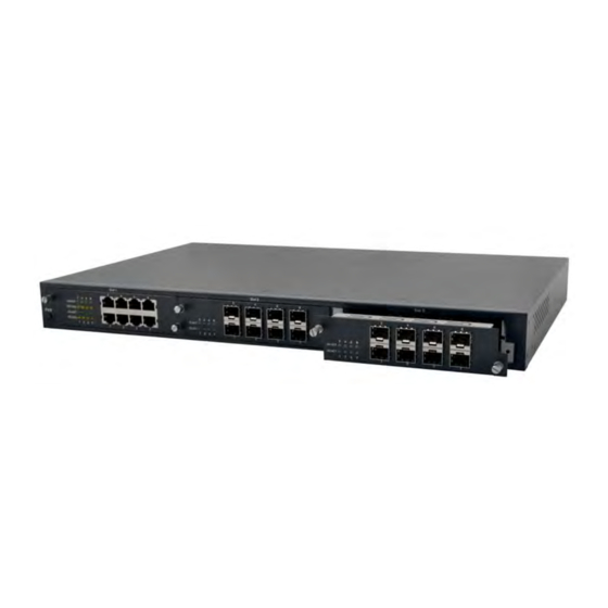
The ComNet™ CWGE2FE24MODMS Managed Ethernet Switch chassis provides up to twenty-six ports of Ethernet
connectivity through the use of three eight-port expansion modules and two rear-mounted fixed combo ports. This
Ethernet switch is easily configurable by selecting, sold separately, eight port modules that allow for all copper, or
all optical with SFP modules making the CWGE2FE24MODMS switch available for use with either conventional UTP
copper or fiber media. The twenty-four modular ports support the 10/100 Mbps electrical or 100Mbps optical
Ethernet IEEE 802.3 protocol. Auto-negotiating and auto-MDI/MDIX features are provided for simplicity and ease of
installation on electrical ports. Two additional ports are Gigabit combo SFP ports. These network managed layer 2
switches are optically and electrically compatible with IEEE 802.3 compliant Ethernet devices. Plug-and-play
design ensures ease of installation, and no electrical or optical adjustments are ever required. The
CWGE2FE24MODMS incorporates LED indicators for monitoring the operating status of the managed switch and
network. These units are rack mountable. The CWGE2FE24MODMS and its corresponding modules are designed
for installation in benign (0º – +45º C) operating environments.
Advertisement
Table of Contents

Related Manuals for Comnet CWGE2FE24MODMS


Summary of Contents for Comnet CWGE2FE24MODMS
- Page 1 Ethernet switch is easily configurable by selecting, sold separately, eight port modules that allow for all copper, or all optical with SFP modules making the CWGE2FE24MODMS switch available for use with either conventional UTP copper or fiber media. The twenty-four modular ports support the 10/100 Mbps electrical or 100Mbps optical Ethernet IEEE 802.3 protocol.
-
Page 3: Table Of Contents
Contents 1. INTRODUCTION....................... 1 Features ..........................2 Software Features......................3 Package Contents......................5 Ethernet Switching Technology..................6 2. HARDWARE DESCRIPTION ................... 7 Physical Dimension......................7 Front Panel......................... 7 LED Indicators........................8 Rear Panel ......................... 9 Desktop Installation......................10 Attaching Rubber Feet ....................10 Rack-mounted Installation.................... - Page 4 System Information ......................20 IP ADDRESS Configuration ..................... 21 DHCP Server – System configuration................22 DHCP Client – System Configuration ................23 DHCP Server - Port and IP ADDRESS Bindings ............. 23 TFTP - Update Firmware ....................24 TFTP – Restore Configuration ..................25 TFTP - Backup Configuration...................
- Page 5 Rapid Spanning Tree ....................... 53 RSTP - System Configuration................... 53 RSTP - Port Configuration ..................54 SNMP Configuration ......................56 System Configuration....................56 Trap Configuration ....................57 SNMPV3 Configuration..................... 58 Context Table ..................... 58 User Profile....................58 Group Table....................59 Access Table ....................
- Page 6 Diagnosing LED Indicators....................75 Cabling........................75 7. TECHNICAL SPECIFICATION................76...
-
Page 7: Introduction
1. Introduction The CWGE2FE24MODMS 26 Port Combo Managed Switch is a modular switch that can be used to build high-performance switched workgroup networks. This switch is a store-and-forward device that offers low latency for high-speed networking. The Switch is targeted at workgroup, department or backbone computing environments. -
Page 8: Features
Features Conforms to IEEE802.3 10BASE-T, 802.3u 100BASE-TX/FX, 802.3ab 1000BASE-T, 802.3z Gigabit SX/LX 3 slots for 8 ports 10/100TX or 8 ports 100Mbps using SFP modules IEEE802.3x Flow control Flow control for full duplex Backpressure for half duplex High back-plane bandwidth 8.8Gbps Supports IEEE802.3ad Port trunk with LACP Broadcast storm filter supported IGMP supports for Multi Media application... -
Page 9: Software Features
Software Features Management SNMP v1/v2c/v3, Web, Telnet, CLI, RMON1 Software Upgrade TFTP and Console firmware upgradeable RFC 3418 SNMP MIB RFC 1213 MIBII RFC 2011 MIB RFC 1493 Bridge MIB RFC 2674 VLAN RFC 1215 Trap MIB RFC 1643 Ethernet like RMON1 Private MIB Cold/warm start trap, link down/link up trap, authorization... - Page 10 Port based VLAN, up to 24 groups IEEE802.1Q Tag VLAN VLAN Static VLAN groups up to 256, Dynamic VLAN group up to 2048, VLAN ID from 1 to 4094. GVRP up to 256 groups Port based, Tag based, IP ADDRESS v4 Type of service, QOS Policy IP ADDRESS v4 Different service.
-
Page 11: Package Contents
CWGE2FE24MODMS switch Four Rubber Feet RS-232 Cable Rack-mounted Kit Power Cord User Guide CD-ROM Package Contents Compare the contents of the CWGE2FE24MODMS package with the standard checklist above. If any item is missing or damaged, please contact ComNet for service. -
Page 12: Ethernet Switching Technology
Ethernet Switching Technology Ethernet Switching Technology dramatically boosted the usable total bandwidth of a network, eliminated congestion problems inherent with CSMA/CD (Carrier Sense multIP Address le access with Collision Detection) protocol, and greatly reduced unnecessary transmission. This revolutionized networking. First, by allowing two-way simultaneous transmission over the same port (Full-duplex), it essentially doubled the bandwidth. -
Page 13: Hardware Description
Physical Dimension The CWGE2FE24MODMS switch has a physical dimension of 440mm(W) x 280mm(D) x 44mm(H). Front Panel The Front Panel of the CWGE2FE24MODMS switch supports 2 kinds of port modules. Please refer to the module user guide for further information. -
Page 14: Led Indicators
LED Indicators Accompanying the Copper/SFP combo ports, four LED indicators are located on the rear panel beside each combo port. The LEDs indicate the status of Link/Activity, Full-Duplex/Collision, and transmission speed for the respective ports. The table below gives definition for each LED indicator. Status Description Green... -
Page 15: Rear Panel
The 3-pronged power plug, 2 fans, DC power input, 2 Gigabit Copper/SFP combo port, and one RS-232 console port are located at the rear Panel of the CWGE2FE24MODMS switch as shown in Figure 2-1. The Switch will work with AC power in the range of 100-240V AC, 50-60Hz. -
Page 16: Desktop Installation
Desktop Installation Set the switch on a sufficiently large flat space with a power outlet nearby. The surface where you put your switch should be clean, smooth, level and sturdy. Make sure there is enough clearance around the switch to allow attachment of cables, power cord and allow air circulation. -
Page 17: Rack-Mounted Installation
Rack-mounted Installation The CWGE2FE24MODMS switch comes with a rack-mounted kit and can be mounted in an EIA standard size, 19-inch Rack. The switch can be placed in a wiring closet with other equipment. Perform the following steps to rack mount the switch: Position one bracket to align with the holes on one side of the switch and secure it with the smaller bracket screws. -
Page 18: Power On
Note: For proper ventilation, allow about at least 4 inches (10 cm) of clearance on the front and 3.4 inches (8 cm) on the back of the switch. This is especially important for enclosed rack installation. Power On Connect the power cord to the power socket on the rear panel of the switch. The other side of power cord connects to the power outlet. -
Page 19: Network Application
This section provides you a few samples of network topology in which the switch is used. In general, the CWGE2FE24MODMS switch is designed as a segment switch. That is, with its large Address table (8000 MAC Address) and high performance, it is ideal for interconnecting networking segments. -
Page 20: Connecting To The Switch
Connecting to the Switch The Console port is a female DB-9 connector that enables a connection to a PC or terminal for monitoring and configuring the Switch. Use the supplied RS-232 cable with a male DB-9 connector to connect a terminal or PC to the Console port. The Console configuration (out of band) allows you to set the switch for remote terminal as if the console terminal were directly connected to it. -
Page 21: Console Management
4. Console Management Login in the Console Interface When the connection between switch and PC is established, turn on the PC and run a terminal emulation program or Hyper Terminal and configure its communication parameters to match the following default characteristics of the console port: Baud Rate: 9600 bps Data Bits: 8 Parity: none... -
Page 22: Module Hot-Swapping
Console login screen Module Hot-Swapping The CWGE2FE24MODMS 26 Port Combo Managed Switch supports module interchanging. The user can insert or pull the module out of the slot without powering down the switch. Once the module is fully inserted, the LEDs on the module panel will all light on at the same time. -
Page 23: Web-Based Management
5. Web-Based Management This section introduces the configuration and functions of the Web-Based management. About Web-based Management Inside the CPU board of the switch, there exists an embedded HTML website residing in flash memory. It offers advanced management features and allows users to manage the switch from anywhere on the network through a standard browser such as Microsoft Internet Explorer. -
Page 24: System Login
System Login Launch the Internet Explorer on the PC Key in “http:// “+” the IP Address of the switch”, and then Press “Enter”. The login screen will appear right after Key in the user name and password. The default for each is “admin” Login screen Press the “Enter”... -
Page 25: Main Interface
Main interface Main interface... -
Page 26: System Information
System Information Assigning the system name, location and viewing the system information System Name: Assign the name of switch. The maximum length is 64 bytes System Description: Display the description of switch. Read-only cannot be modified System Location: Assign the switch’s physical location. The maximum length is 64 bytes System Contact: Enter the name of contact person or organization Firmware Version: Display the switch’s firmware version... -
Page 27: Ip Address Configuration
IP ADDRESS Configuration The user can configure the IP Address Settings and DHCP client function DHCP Client: Enable or disable the DHCP client function. When DHCP client function is enabled, the switch will be assigned an IP Address from the network DHCP server. -
Page 28: Dhcp Server - System Configuration
DHCP Server – System configuration The system provides the DHCP server function. By enabling the DHCP server function, the switch system will be the DHCP server. DHCP Server: Enable or Disable the DHCP Server function. Enable – the switch will be the DHCP server on your local network. -
Page 29: Dhcp Client - System Configuration
DHCP Server Configuration interface DHCP Client – System Configuration When the DHCP server function is active, the system will collect the DHCP client information and display in here. DHCP Client Entries interface DHCP Server - Port and IP ADDRESS Bindings You can assign the specific IP Address that is one of the IP Addresses in dynamic IP Address pool to the specific port. -
Page 30: Tftp - Update Firmware
Port and IP ADDRESS Bindings interface TFTP - Update Firmware The functions allow a user to update the switch firmware. Before updating, make sure you have your TFTP server ready; and the firmware image is on the TFTP server. TFTP Server IP Address: fill in your TFTP server IP Address. Firmware File Name: the name of firmware image. -
Page 31: Tftp - Restore Configuration
TFTP – Restore Configuration You can restore the EEPROM value of the switch from the TFTP server. Before doing this, you must have a prior backup of the configuration in the TFTP server then the switch can restore the backup file to its EEPROM. TFTP Server IP Address: fill in the TFTP server IP Address. -
Page 32: System Event Log - Syslog Configuration
Backup Configuration interface System Event Log – Syslog Configuration Configure the system event mode, that you want to collect, and system log server IP ADDRESS. Syslog Client Mode: select the system log mode – client only, server only, or both S/C. -
Page 33: System Event Log - Smtp Configuration
Syslog Configuration interface System Event Log - SMTP Configuration You can set up the mail server IP Address, Email account, account password, and forwarded Email account for receiving the event alert. Email Alert: enable or disable the Email alert function. SMTP Server IP Address: set up the mail server IP Address (when Email Alert enabled, this function will then be available). - Page 34 It must be an existing Email account on the mail server that you had set up in SMTP Server IP Address column. Password: The Email account password. Confirm Password: reconfirm the password. Receipt e-mail Address 1 ~ 6: you can assign up to 6 Email accounts also to receive the alert.
-
Page 35: System Event Log - Event Configuration
System Event Log - Event Configuration You can select the system log events and SMTP events. When selected events occur, the system will send out the log information. Also, per port log and SMTP events can be selected. After configure, Select System event selection: 4 selections –... - Page 36 Event Configuration interface...
-
Page 37: Sntp Configuration
SNTP Configuration You can configure the SNTP (Simple Network Time Protocol) settings. The SNTP allows you to synchronize switch clocks with the Internet. SNTP Client: enable or disable SNTP function to get the time from the SNTP server. Daylight Saving Time: enable or disable daylight saving time function. When daylight saving time is enabled, you need to configure the daylight saving time period. - Page 38 Nome, Alaska -11 hours 1 am CET - Central European FWT - French Winter MET - Middle European +1 hour 1 pm MEWT - Middle European Winter SWT - Swedish Winter EET - Eastern European, +2 hours 2 pm USSR Zone 1 BT - Baghdad, USSR Zone 2 +3 hours 3 pm...
-
Page 39: Ip Address Security
Daylight Saving Offset (mins): set up the offset time. Switch Timer: display the switch current time. Select SNTP Configuration interface IP Address Security IP Address security function allows user to assign 10 specific IP Addresses that have permission to access the switch through the web browser for securing switch management. -
Page 40: User Authentication
IP Addresses can access and manage the switch through the Web browser And then, select button to apply the configuration [NOTE] Remember to execute the “Save Configuration” action, otherwise the new configuration will lose when switch powers off. IP ADDRESS Security interface User Authentication Change web management login user name and password for the management security issue... -
Page 41: Advanced Configuration-Broadcast Storm Filter
User Authentication interface Advanced Configuration-Broadcast Storm Filter This page enables user to select the filter packet type. All the packet types filtering conditions could be selected at the same time. Flooded Unicast/Multicast Packets: When this check box is marked, the switch will filter the packet type of Flooded Unicast/Multicast. -
Page 42: Advanced Configuration-Aging Time
Broadcast Storm Filter Advanced Configuration-Aging Time This tab is used to assign the aging time of MAC table. Aging Time of MAC Table: Select the aging time as OFF, 150 sec, 300 sec, or 600 sec. When MAC table is not used within the aging time, the MAC Address table will then be cleared. -
Page 43: Advanced Configuration-Jumbo Frame
Advanced Configuration-Jumbo Frame This tab is used to enable the jumbo frame function. Enable Jumbo Frame: When this item is marked, the Gigabit port of the switch (on the rear panel) extends the frame to 9022bytes. Select button to make the setting effective. Jumbo Frame Setting... -
Page 44: 1000Tx Cable Length
1000TX Cable Length This tab is used to allow port 25 and port 26 to support Cat5e or Cat6 cable length longer than 10 meters. To support long cable: Uncheck the check box for the port(s) you would like to effect. -
Page 45: Port Statistics
Port Statistics The following information provides the current port statistic information Select button to clean all counts Port Statistics interface Port Control In Port control, you can view every port status that depended on user setting and the negotiation result. Port: select the port that you want to configure. - Page 46 setting is disable then will not receive or transmit any packet. Negotiation: set auto negotiation status of port. Speed: set the port link speed. Duplex: set full-duplex or half-duplex mode of the port. Flow Control: set flow control function as Symmetric or Asymmetric in Full Duplex mode.
-
Page 47: Port Trunk
Port Trunk The Link Aggregation Control Protocol (LACP) provides a standardized means for exchanging information between Partner Systems on a link to allow their Link Aggregation Control instances to reach agreement on the identity of the Link Aggregation Group to which the link belongs, move the link to that Link Aggregation Group, and enable its transmission and reception functions in an orderly manner. - Page 48 State Activity page. Select button to delete Trunk Group. Select the Group ID and select button. Port Trunk—Aggregator Setting interface...
-
Page 49: Aggregator Information
Aggregator Information When you have set the LACP aggregator, you will see the related information here. Port Trunk – Aggregator Information interface... -
Page 50: State Activity
State Activity When you have set up the LACP aggregator, you can configure port state activity. You can mark or un-mark the port. When you mark the port and select button the port state activity will change to Active. Opposite is Passive. Active: The port automatically sends LACP protocol packets. -
Page 51: Port Mirroring
Port Mirroring The Port mirroring is a method for monitoring traffic in switched networks. Traffic through ports can be monitored by one specific port. That means traffic goes in or out monitored (source) ports and will be duplicated into an analysis (mirror) port. Mode: Select the mirroring mode by pulling down the selection item menu: RX, TX or Both RX ⁄... -
Page 52: Rate Limiting
Rate Limiting You can set up every port’s bandwidth rate here. Rate Limiting interface All the ports support packet ingress and egress rate control. For example, assume port 1 is 10Mbps, users can set its effective egress rate as 2Mbps, ingress rate as 1Mbps. -
Page 53: Vlan Configuration
VLAN configuration A Virtual Local Area Network (VLAN) is a logical network grouping that limits the broadcast domain that would allow you to isolate network traffic, so only the members of the VLAN will receive traffic from the members of the same VLAN. Basically, creating a VLAN from a switch is the logical equivalent of reconnecting a group of network devices to another Layer 2 switch. - Page 54 VLAN – Port Based interface Select to add a new VLAN group (The maximum VLAN group is up to 64 VLAN groups) Enter the VLAN name, group ID and group the members of the VLAN group Select...
- Page 55 VLAN—Port Based Add interface You will see the VLAN displays. button to delete unwanted VLAN. button to modify existing VLAN group. [NOTE] Remember to execute the “Save Configuration” action, otherwise the new configuration will be lost when the switch powers off.
-
Page 56: 802.1Q Vlan
802.1Q VLAN Tagged-based VLAN is an IEEE 802.1Q specification standard. Therefore, it is possible to create a VLAN across devices from different switch venders. IEEE 802.1Q VLAN uses a technique to insert a “tag” into the Ethernet frames. Tag contains a VLAN Identifier (VID) that indicates the VLAN numbers. - Page 57 802.1q VLAN interface...
-
Page 58: Group Configuration
Group Configuration Edit the existing VLAN Group. Select the VLAN group in the table list. Select Group Configuration interface You can Change the VLAN group name and VLAN ID. Select Group Configuration interface... -
Page 59: Rapid Spanning Tree
Rapid Spanning Tree The Rapid Spanning Tree Protocol (RSTP) is an evolution of the Spanning Tree Protocol and provides for faster spanning tree convergence after a topology change. The system also supports STP and the system will auto detect the connected device that is running STP or RSTP protocol. -
Page 60: Rstp - Port Configuration
RSTP System Configuration interface RSTP - Port Configuration You can configure path cost and priority of every port. 1. Select the port in Port column. 1. Path Cost: The cost of the path to the other bridge from this transmitting bridge at the specified port. - Page 61 two or more bridges (i.e. it is served by a shared medium LAN segment). This function allows the P2P status of the link to be manIP Address ulated administratively. True is P2P enabling. False is P2P disabling. RSTP Port Configuration interface 4.
-
Page 62: Snmp Configuration
SNMP Configuration Simple Network Management Protocol (SNMP) is the protocol developed to manage nodes (servers, workstations, routers, switches and hubs etc.) on an IP network. SNMP enables network administrators to manage network performance, find and solve network problems, and plan for network growth. Network management systems learn of problems by receiving traps or change notices from network devices implementing SNMP. -
Page 63: Trap Configuration
SNMP System Configuration interface Trap Configuration A trap manager is a management station that receives traps, the system alerts generated by the switch. If no trap manager is defined, no traps will issue. Create a trap manager by entering the IP Address of the station and a community string. To define management stations as trap manager and enter SNMP community strings and selects the SNMP version. -
Page 64: Snmpv3 Configuration
Trap Managers interface SNMPV3 Configuration Configure the SNMP V3 function including Context Table, User Profile, Group Table, Access Table and MIBView Table. Context Table Configure SNMP v3 context table. Assign the context name of context table. Select to add context name. Select to remove unwanted context name. -
Page 65: Group Table
SNMP V3 configuration interface Group Table Configure SNMP v3 group table. Security Name (User ID): assign the user name that you have set up in user table. Group Name: set up the group name. Select to add context name. Select to remove unwanted context name. -
Page 66: Mib View Table
Context Match Rule: select the context match rule. Read View Name: set up the read view. Write View Name: set up the write view. Notify View Name: set up the notify view. Select to add context name. Select to remove unwanted context name. MIB view Table Configure MIB view table. - Page 67 to process priority queue from High to Lowest queue. For example, as the system processes 1 frames of the lowest queue, 2 frames of the low queue, 4 frames of the middle queue, and 8 frames of the high queue will be processed at the same time in accordance with the 8,4,2,1 policy rule.
- Page 68 QoS Configuration interface...
-
Page 69: Igmp Configuration
IGMP Configuration The Internet Group Management Protocol (IGMP) is an internal protocol of the Internet Protocol (IP Address) suite. IP Address manages multicast traffic by using switches, routers, and hosts that support IGMP. Enabling IGMP allows the ports to detect IGMP queries and report packets and manage IP Address multicast traffic through the switch. - Page 70 IGMP Configuration interface LLDP LLDP (Link Layer Discovery Protocol) function allows the switch to advertise its information to other nodes on the network and store the information it discovers. LLDP Protocol: Disable or enable LLDP function. LLDP Interval: Set the interval of learning the information time in second. Select LLDP Configuration interface Security...
-
Page 71: 802.1X/Radius Configuration
802.1X/Radius Configuration 802.1x is an IEEE authentication specification that allows a client to connect to a wireless access point or wired switch but prevents the client from gaining access to the Internet until it provides authority, like a user name and password that are verified by a separate server. -
Page 72: 802.1X Port Configuration
802.1x System Configuration interface 802.1x Port Configuration You can configure 802.1x authentication state for each port. The State provides Disable, Accept, Reject and Authorize. Use the “Space” key to change the state value. Reject: the specified port is required to be held in the unauthorized state. Accept: the specified port is required to be held in the authorized state. -
Page 73: Misc Configuration
802.1x Per Port Setting interface Misc Configuration Quiet Period: set the time period during which the port does not try to acquire a supplicant. TX Period: set the time period the port should wait for retransmit next EAPOL PDU during an authentication session. Supplicant Timeout: set the period of time the switch waits for a supplicant response to an EAP request. -
Page 74: Mac Address Table
Max Requests: set the number of authentication attempts that must time-out before authentication fails and the authentication session ends. Re-authentication period: set the period of time after which clients connected must be re-authenticated. Select 802.1x Misc Configuration interface MAC Address Table Use the MAC Address table to ensure the port security. -
Page 75: Mac Filtering
You can add static MAC Address in switch MAC table. MAC Address: Enter the MAC Address of the port that should permanently forward traffic, regardless of the device network activity. VID: Type in VID of the MAC Address. Port No.: pull down the selection menu to select the port number. Select If you want to delete the MAC Address from filtering table, select the MAC Address and select... -
Page 76: All Mac Addresses
MAC Filtering interface MAC Address: Enter the MAC Address that you want to filter. VID: Type in the VID of the MAC Address. Select If you want to delete the MAC Address from the filtering table, select the MAC Address and select All MAC Addresses You can view the port that connected device’s MAC Address and related devices’... -
Page 77: Access Control List
All MAC Address Interface Access Control List Group Id: Type in the Group ID from 1 to 255. Action: Permit and Deny. VLAN: Select any or a particular VID. Packet type: Select packet type – IP ADDRESS v4 or Non-IP ADDRESS v4 Src IP Address: Select any or assign an IP Address with Subnet Mask for source IP Address . -
Page 78: Factory Default
Access Control List interface Factory Default Reset switch to default configuration. Select to reset all configurations to the default value. Factory Default Interface... -
Page 79: Save Configuration
Save Configuration To ensure that all configurations will be saved, select to save the configuration to the flash memory. Save Configuration interface System Reboot Reboot the switch in software reset. Select to reboot the system. System Reboot Interface... -
Page 80: Problem Solving
6. Problem Solving This section is intended to help you solve the most common problems on the CWGE2FE24MODMS switch. Incorrect connections The switch port can auto-detect straight or crossover cables when you link the switch with other Ethernet devices. For the RJ-45 connector use the correct UTP or STP cable, 10/100Mbps port use 2-pair twisted cable and Gigabit 1000T port use 4-pair twisted cable. -
Page 81: Diagnosing Led Indicators
However, if the switch powers off after running for a while check for loose power connections, power losses or surges at power outlet. If you still cannot resolve the problem, contact ComNet for assistance. Cabling... -
Page 82: Technical Specification
7. Technical Specification This section provides the specifications of the CWGE2FE24MODMS switch, and the following table lists these specifications. IEEE802.3 10BASE-T IEEE802.3u 100BASE-TX/100BASE-FX IEEE802.3z Gigabit SX/LX IEE802.3ab Gigabit 1000T IEEE802.3x Flow Control and Back pressure Standards IEEE802.3ad Port trunk with LACP IEEE802.1d Spanning tree protocol... - Page 83 8 port 10/100TX module with RJ-45 connector 8 port 100Mbps multi mode fiber module with SC connector Expansion module 8 port 100Mbps single mode fiber module with SC connector 8 port 100Mbps SFP module MAC Address 8K MAC address table with Auto learning function Packet Buffer 4 Mbits for packet buffer Flash ROM...
- Page 84 ComNet Customer Service Customer Care is ComNet Technology’s global service center, where our professional staff is ready to answer your questions at any time. Email address of ComNet Global Service Center: customercare@ComNet.net World Headquarters ComNet Europe Ltd 3 Corporate Drive...
Need help?
Do you have a question about the CWGE2FE24MODMS and is the answer not in the manual?
Questions and answers