Table of Contents
Advertisement
INSTALLATION AND OPERATION MANUAL
CNGE24MS
EnvironmEntally HardEnEd managEd EtHErnEt SwitcH
witH (8) 100/1000BaSE-FX & (16) gigaBit comBo PortS
v1.4 February 25, 2013
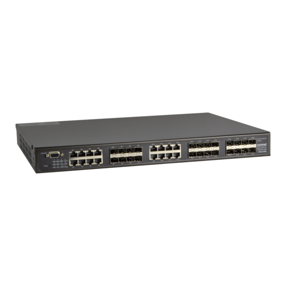
The ComNet
CNGE24MS has eight 100/1000Base-FX SFP ports and sixteen Gigabit
™
combo ports that allow for TX or FX transmission. All SFP ports utilize ComNet Small
Form Factor (SFP) pluggable modules for the selection of fiber and connector type and
distance. The IEEE802.3-compliant unit offers multiple Ethernet redundancy protocols
(ComRing, C-Ring, and MSTP/RSTP/STP) which protect your applications from network
interruptions or temporary malfunctions by redirecting transmission within the
network. The switch provides advanced IP-based management that can limit the
maximum bandwidth for each connected IP device, allowing the user to adjust
usage. Application-based QoS can set a higher priority for data streaming. The Device-
Binding function can prevent unauthorized network access, increasing security. The
unit also provides advanced DOS/DDOS auto prevention. If IP flow becomes too large,
too quickly, the switch will lock the source IP address for a set period preventing
unauthorized access. The switch offers centralized and convenient management and
is also configurable by Web-based Telnet, and Console (CLI) configurations.
Advertisement
Table of Contents

Subscribe to Our Youtube Channel
Related Manuals for Comnet CNGE24MS


Summary of Contents for Comnet CNGE24MS
- Page 1 CNGE24MS has eight 100/1000Base-FX SFP ports and sixteen Gigabit ™ combo ports that allow for TX or FX transmission. All SFP ports utilize ComNet Small Form Factor (SFP) pluggable modules for the selection of fiber and connector type and distance. The IEEE802.3-compliant unit offers multiple Ethernet redundancy protocols...
-
Page 2: Table Of Contents
INSTALLATION AND OPERATION MANUAL CNGE24MS Contents Regulatory Compliance Statement Warranty Disclaimer Safety Indications Overview Introduction Software Features Hardware Features Hardware Overview Front Panel Rear Panel Rack mount kit assembly Front Panel LEDs Cables Ethernet Cables 10/100/1000BASE-T(X) Pin Assignments Console Cable... -
Page 3: Regulatory Compliance Statement
ComNet warrants that all ComNet products are free from defects in material and workmanship for a specified warranty period from the invoice date for the life of the installation. ComNet will repair or replace products found by ComNet to be defective within this warranty period, with shipment expenses apportioned by ComNet and the distributor. -
Page 4: Overview
QoS. Application-based QoS can set highest priority for data stream according to TCP/UDP port number. And all functions of CNGE24MS can also be managed centralized and convenient by e-Console, as well as the Web-based interface, Telnet and console (CLI) configuration. -
Page 5: Software Features
INSTALLATION AND OPERATION MANUAL CNGE24MS Software Features » Fastest Redundant Ethernet Ring (Recovery time <20ms over 250 units connection) » Supports Ring Coupling, Dual Homing, and RSTP-over-Ring » Supports SNMPv1/v2/v3 & RMON & Port base/IEEE 802.1Q VLAN Network Management » Event notification by Email, SNMP trap and Relay Output »... -
Page 6: Hardware Features
INSTALLATION AND OPERATION MANUAL CNGE24MS Hardware Features » 3 × Redundant power inputs » Operating Temperature: -40 to 75°C » Storage Temperature: -40 to 85°C » Operating Humidity: 5% to 95%, non-condensing » Casing: IP-30 Aluminum » 16 × Combo ports with 10/100/1000Base-T(X) and 100/1000Base-X SFP »... -
Page 7: Hardware Overview
INSTALLATION AND OPERATION MANUAL CNGE24MS Hardware Overview Front Panel The following table describes the labels that are affixed to the CNGE24MS. Port Description SFP ports 16 × 100/1000BaseX on SFP port(combo) & 8 × 100/1000BaseX on SFP port Giga Ethernet Port 16 × 10/100/1000Base-T (combo) Console Use RS-232 with DB9 connecter to manage switch. -
Page 8: Rear Panel
LED for RMT: System is accessed remotely. » LED for Fault: Indicates unexpected event occurred. Rear Panel The rear panel of CNGE24MS is displayed as below: CNGE24MS Rear Panel 1. Power Switch 2. Power input for AC 100V~240V / 50~60Hz. -
Page 9: Rack Mount Kit Assembly
INSTALLATION AND OPERATION MANUAL CNGE24MS Rack mount kit assembly You can find the rack-mount kit and the screws in the packing box. Please assemble the rack- mount kit on the switch with screws as shown below: inS_cngE24mS_rEv– Tech SupporT: 1.888.678.9427... -
Page 10: Front Panel Leds
INSTALLATION AND OPERATION MANUAL CNGE24MS Front Panel LEDs LED indicators Color Status Description Green PWR1 linked Green PWR2 linked Green PWR3 linked Green The power module is in PWR UP state Blinking The system is upgrading firmware Green System resets to default configuration... -
Page 11: Cables
Cables Ethernet Cables The CNGE24MS switches have standard Ethernet ports. According to the link type, the switches use CAT 3, 4, 5, & 5e UTP cables to connect to any other network device (PCs, servers, switches, routers, or hubs). Please refer to the following table for cable specifications. - Page 12 Note: “+” and “-” signs represent the polarity of the wires that make up each wire pair. The CNGE24MS switches support auto MDI/MDI-X operation. You can use a straight-through cable to connect PC to switch. The following table below shows the 10/100BASE-T(X) MDI and...
-
Page 13: Sfp
Note: “+” and “-” signs represent the polarity of the wires that make up each wire pair. The Switch has fiber optic ports that utilize SFP connectors. ComNet offers a wide selection of SFP modules that offer different fiber type, connector type and distances. Please remember that the TX port of Switch A should be connected to the RX port of Switch B. -
Page 14: Console Cable
INSTALLATION AND OPERATION MANUAL CNGE24MS Console Cable Each CNGE24MS switch can be managed by its console port. You can connect them to PC via an RS-232 cable with DB-9 female connector. DB-9 Cable inS_cngE24mS_rEv– Tech SupporT: 1.888.678.9427 02/18/13 PagE 14... - Page 15 INSTALLATION AND OPERATION MANUAL CNGE24MS DB-9 Male DB-9 Female Male Connector Female Connector Received Line Signal Detect (Received by DTE Received Line Signal Detect (Transmitted Device) from DCE Device) Received Data (Received by DTE Device) Transmitted Data (Transmitted from DCE...
-
Page 16: Web Management
INSTALLATION AND OPERATION MANUAL CNGE24MS WEB Management Attention: While installing and upgrading firmware, please remove physical loop connection first. DO NOT power off equipment while the firmware is upgrading! Configuration by Web Browser This section provides instruction on configuration through the Web browser. - Page 17 INSTALLATION AND OPERATION MANUAL CNGE24MS System Login 1. Launch your Web Browser. 2. Type http:// and the IP address of the switch. Press Enter. 3. The login screen appears. 4. Enter username and password. The default username and password is admin.
- Page 18 INSTALLATION AND OPERATION MANUAL CNGE24MS Main Interface Main interface Basic Setting System Information The switch system information is provided here. System Information interface inS_cngE24mS_rEv– Tech SupporT: 1.888.678.9427 02/18/13 PagE 18...
- Page 19 INSTALLATION AND OPERATION MANUAL CNGE24MS Label Description System Name The administrator-assigned name for this managed node. By convention, this is the node’s fully qualified domain name. A domain name is a text string drawn from the alphabet (A-Z, a-z), digits (0-9), minus sign (-). No space characters are permitted as part of a name.
- Page 20 INSTALLATION AND OPERATION MANUAL CNGE24MS IP Setting Configure the switch-managed IP information on this page. Label Description DHCP Client Enable the DHCP client by checking this box. If DHCP fails and the configured IP address is zero, DHCP will retry. If DHCP fails and the configured IP address is non-zero, DHCP will stop and the configured IP settings will be used.
- Page 21 INSTALLATION AND OPERATION MANUAL CNGE24MS HTTPS Label Description Mode Indicates the HTTPS mode operation. Possible modes are: Enabled: Enable HTTPS mode operation. Disabled: Disable HTTPS mode operation. Save Select to save changes. Reset Select to undo any changes made locally and revert to previously saved values.
- Page 22 INSTALLATION AND OPERATION MANUAL CNGE24MS LLDP LLDP Parameters This page allows the user to inspect and configure the current LLDP port settings. ˇ ˇ ˇ Label Description TX Interval The switch periodically transmits LLDP frames to its neighbors for keeping the network discovery information up-to-date. The interval between each LLDP frame is determined by the TX Interval value.
- Page 23 INSTALLATION AND OPERATION MANUAL CNGE24MS LLDP Neighbor Information This page provides a status overview for all LLDP neighbors. The displayed table contains a row for each port on which an LLDP neighbor is detected. The columns hold the following information:...
- Page 24 INSTALLATION AND OPERATION MANUAL CNGE24MS LLDP Statistics This page provides an overview of all LLDP traffic. Two types of counters are shown. Global counters are counters that refer to the whole network of switches, while local counters refer to counters for the currently selected switch.
- Page 25 INSTALLATION AND OPERATION MANUAL CNGE24MS Local Counters Label Description Local Port The port on which LLDP frames are received or transmitted. TX Frames The number of LLDP frames transmitted on the port. Rx Frames The number of LLDP frames received on the port.
- Page 26 INSTALLATION AND OPERATION MANUAL CNGE24MS Backup/Restore Configuration You can save/view or load the switch configuration. The configuration file is in XML format with a hierarchy of tags. Firmware Update This page facilitates an update of the firmware controlling the switch.
- Page 27 INSTALLATION AND OPERATION MANUAL CNGE24MS DHCP Dynamic Client List When the DHCP server function is activated, the system will collect the DHCP client information and display in here. DHCP Client List You can assign the specific IP address that is in the assigned dynamic IP range to the specific port.
- Page 28 INSTALLATION AND OPERATION MANUAL CNGE24MS Label Description Port This is the logical port number for this row. Link The current link state is displayed graphically. Green indicates the link is up and red that it is down. Current Link Provides the current link speed of the port.
- Page 29 INSTALLATION AND OPERATION MANUAL CNGE24MS Rate Limit Configure the switch port rate limit for Policers and Shapers on this page. Label Description Port The logical port for the settings contained in the same row. Policer Enabled Enable or disable the port policer. The default value is “Disabled”.
- Page 30 INSTALLATION AND OPERATION MANUAL CNGE24MS Port Trunk Trunk Configuration This page is used to configure the Aggregation hash mode and the aggregation group. Label Description Source MAC The Source MAC address can be used to calculate the destination port Address for the frame.
- Page 31 INSTALLATION AND OPERATION MANUAL CNGE24MS Label Description Group ID Indicates the group ID for the settings contained in the same row. Group ID “Normal” indicates there is no aggregation. Only one group ID is valid per port. Port Members Each switch port is listed for each group ID. Select a radio button to include a port in an aggregation, or clear the radio button to remove the port from the aggregation.
- Page 32 INSTALLATION AND OPERATION MANUAL CNGE24MS LACP Port Configuration This page allows the user to inspect the current LACP port configurations, and possibly change them as well. ˇ ˇ ˇ Label Description Port Indicates the group ID for the settings contained in the same row. Group ID “Normal”...
- Page 33 INSTALLATION AND OPERATION MANUAL CNGE24MS LACP System Status This page provides a status overview for all LACP instances. Label Description Aggr ID The Aggregation ID associated with this aggregation instance. For LLAG the id is shown as ‘isid:aggr-id’ and for GLAGs as ‘aggr-id’...
- Page 34 INSTALLATION AND OPERATION MANUAL CNGE24MS LACP Status This page provides a status overview for LACP status for all ports. Label Description Port The switch port number. LACP ‘Yes’ means that LACP is enabled and the port link is up. ‘No’ means that LACP is not enabled or that the port link is down.
- Page 35 INSTALLATION AND OPERATION MANUAL CNGE24MS LACP Statistics This page provides an overview for LACP statistics for all ports. Label Description Port The switch port number LACP Shows how many LACP frames have been sent from each port Transmitted LACP Received Shows how many LACP frames have been received at each port.
- Page 36 INSTALLATION AND OPERATION MANUAL CNGE24MS Redundancy C-Ring C-Ring is the most powerful Ring in its class. The recovery time of C-Ring is less than 20 ms for Gigabit Ethernet switches. It can reduce unexpected damage caused by network topology change. C-Ring Supports 3 Ring topologies: C-Ring, Coupling Ring, and Dual Homing.
- Page 37 INSTALLATION AND OPERATION MANUAL CNGE24MS Label Description C-Ring Mark to enable C-Ring. Ring Master There should be one and only one Ring Master in a ring. However if there are two or more switches that are set as Ring Masters, the switch with the lowest MAC address will be the actual Ring Master and others will be Backup Masters.
- Page 38 INSTALLATION AND OPERATION MANUAL CNGE24MS Legacy Ring Legacy ring provides support for the switch to be used in an existing ring of ComNet X-Ring enabled switches. X-Ring provides a faster redundant recovery than Spanning Tree topology. The action is similar to STP or RSTP, but the algorithms between them are not the same.
- Page 39 INSTALLATION AND OPERATION MANUAL CNGE24MS COM-Ring You can add ComNet switches into a network constructed by another ring technology and enable COM-Ring to cooperate with another vendor’s managed switch. ComRing interface Label Description Enable Enable the COM-Ring function Vendor Select the vendor whose ring you want to join...
- Page 40 INSTALLATION AND OPERATION MANUAL CNGE24MS MSTP Bridge Settings This page allows you to configure RSTP system settings. The settings are used by all RSTP Bridge instances in the Switch Stack. Label Description Protocol Version The STP protocol version setting. Valid values are STP, RSTP and MSTP.
- Page 41 INSTALLATION AND OPERATION MANUAL CNGE24MS MSTI Mapping This page allows the user to inspect the current STP MSTI bridge instance priority configurations, and possibly change them as well. Label Description Configuration The name identifying the VLAN to MSTI mapping. Bridges must...
- Page 42 INSTALLATION AND OPERATION MANUAL CNGE24MS MSTI Priorities This page allows the user to inspect the current STP MSTI bridge instance priority configurations, and possibly change them as well. Label Description MSTI The bridge instance. The CIST is the default instance, which is always active.
- Page 43 INSTALLATION AND OPERATION MANUAL CNGE24MS CIST Ports This page allows the user to inspect the current STP CIST port configurations, and possibly change them as well. This page contains settings for physical and aggregated ports. The aggregation settings are stack global.
- Page 44 INSTALLATION AND OPERATION MANUAL CNGE24MS Label Description Port The switch port number of the logical STP port. STP Enabled Controls whether STP is enabled on this switch port. Path Cost Controls the path cost incurred by the port. The Auto setting will set the path cost as appropriate by the physical link speed, using the 802.1D recommended values.
- Page 45 INSTALLATION AND OPERATION MANUAL CNGE24MS MSTI Ports This page allows the user to inspect the current STP MSTI port configurations, and possibly change them as well. A MSTI port is a virtual port, which is instantiated separately for each active CIST (physical) port for each MSTI instance configured and applicable for the port.
- Page 46 INSTALLATION AND OPERATION MANUAL CNGE24MS Label Description Port The switch port number of the corresponding STP CIST (and MSTI) port. Path Cost Controls the path cost incurred by the port. The Auto setting will set the path cost as appropriate by the physical link speed, using the 802.1D recommended values.
- Page 47 INSTALLATION AND OPERATION MANUAL CNGE24MS STP Bridges This page provides a status overview for all STP bridge instances. The displayed table contains a row for each STP bridge instance, where the columns display the following information: Label Description MSTI The Bridge Instance. This is also a link to the STP Detailed Bridge Status.
- Page 48 INSTALLATION AND OPERATION MANUAL CNGE24MS STP Port Status This page displays the STP CIST port status for port physical ports in the currently selected switch. Label Description Port The switch port number of the logical STP port. CIST Role The current STP port role of the CIST port. The port role can be one of the following values: AlternatePort BackupPort RootPort DesignatedPort.
- Page 49 INSTALLATION AND OPERATION MANUAL CNGE24MS STP Statistics This page displays the RSTP port statistics counters for bridge ports in the currently selected switch. Label Description Port The switch port number of the logical RSTP port. RSTP The number of RSTP Configuration BPDUs received/transmitted on the port.
- Page 50 INSTALLATION AND OPERATION MANUAL CNGE24MS VLAN VLAN Membership Configuration The VLAN membership configuration for the selected stack switch unit switch can be monitored and modified here. Up to 64 VLANs are supported. This page allows for adding and deleting VLANs as well as adding and deleting port members of each VLAN.
- Page 51 INSTALLATION AND OPERATION MANUAL CNGE24MS Example: Portbased VLAN Setting (For ingress port) 1. VLAN Membership Configuration setting port 1 & VID=50 2. VLAN Port 1 Configurations-->Disable VLAN Aware 3. VLAN Port 1 Configuration-->Mode=specific,ID=50 inS_cngE24mS_rEv– Tech SupporT: 1.888.678.9427 02/18/13 PagE 51...
- Page 52 INSTALLATION AND OPERATION MANUAL CNGE24MS (For egress port) 1. VLAN Membership Configuration setting port 2 & VID=50 2. VLAN Port 2 Configuration-->don’t care VLAN Aware 3. VLAN Port 2 Configuration-->Mode=specific, ID=50 (Any packet can enter egress port ) inS_cngE24mS_rEv– Tech SupporT: 1.888.678.9427...
- Page 53 INSTALLATION AND OPERATION MANUAL CNGE24MS 802.1Q Access port Setting (For ingress port) 1. VLAN Membership Configuration setting port & VID=50 2. VLAN Port Configurations-->Enable VLAN Aware 1. VLAN Port Configuration-->Mode=specific,ID=50 inS_cngE24mS_rEv– Tech SupporT: 1.888.678.9427 02/18/13 PagE 53...
- Page 54 INSTALLATION AND OPERATION MANUAL CNGE24MS (For egress port) 1. VLAN Membership Configuration setting port & VID=50 2. VLAN Port Configurations-->Disable VLAN Aware 3. VLAN Port Configuration-->Mode=specific,ID=50 (Untagged & tag=50 packet can enter egress port ) inS_cngE24mS_rEv– Tech SupporT: 1.888.678.9427 02/18/13 PagE 54...
- Page 55 INSTALLATION AND OPERATION MANUAL CNGE24MS 802.1Q Trunk port setting (multi-tag) CNGE24MS CNGE24MS (For ingress port) 1. VLAN Membership Configuration setting port & VID=11,22,33 2. VLAN Port Configurations-->Enable VLAN Aware 3. VLAN Port Configuration-->Mode=specific,ID=11 (when entering packet is untagged frame, added tag = 11 When entering the tagged frame, only VID = 11,22,33 three kinds of packets can pass) inS_cngE24mS_rEv–...
- Page 56 INSTALLATION AND OPERATION MANUAL CNGE24MS (For egress port) 1. VLAN Membership Configuration setting port, VID=11,22,33 2. VLAN Port Configurations-->Enable VLAN Aware 3. VLAN Port Configuration-->Mode=none (Egress port can receive tag=11,22,33 packet In addition, only tag=11 packet can enter egress port) inS_cngE24mS_rEv–...
- Page 57 INSTALLATION AND OPERATION MANUAL CNGE24MS QinQ VLAN Setting CNGE24MS Tag=50 (tag=77) packet ingress Port 1------------------->egress Port 2 (For Ingress port----- Port 1) 1. VLAN Membership Configuration setting port 1, 2 and 3 & VID=50 inS_cngE24mS_rEv– Tech SupporT: 1.888.678.9427 02/18/13 PagE 57...
- Page 58 INSTALLATION AND OPERATION MANUAL CNGE24MS 2. VLAN Port Configuration-->Disable Port 1 VLAN Aware 3. VLAN Port Configuration-->Port 1 Mode=specific, ID=50 inS_cngE24mS_rEv– Tech SupporT: 1.888.678.9427 02/18/13 PagE 58...
- Page 59 INSTALLATION AND OPERATION MANUAL CNGE24MS (For egress port ----Port 2) 1. VLAN Membership Configuration setting port & VID=50 2. VLAN Port Configuration-->Enable Port 2 and 3 VLAN Aware. 3. VLAN Port Configuration-->Mode=none (only tag=50 packet can enter egress port ) inS_cngE24mS_rEv–...
- Page 60 INSTALLATION AND OPERATION MANUAL CNGE24MS Private VLAN The Private VLAN membership configurations for the switch can be monitored and modified here. Private VLANs can be added or deleted here. Port members of each Private VLAN can be added or removed here. Private VLANs are based on the source port mask, and there are no connections to VLANs.
- Page 61 INSTALLATION AND OPERATION MANUAL CNGE24MS Label Description Port Members A check box is provided for each port of a private VLAN. When checked, port isolation is enabled for that port. When unchecked, port isolation is disabled for that port. By default, port isolation is disabled for all ports.
- Page 62 INSTALLATION AND OPERATION MANUAL CNGE24MS SNMP SNMP-System Label Description Mode Indicates the SNMP mode operation. Possible modes are: Enabled: Enable SNMP mode operation. Disabled: Disable SNMP mode operation. Version Indicates the SNMP supported version. Possible versions are: SNMP v1: Set SNMP supported version 1.
- Page 63 INSTALLATION AND OPERATION MANUAL CNGE24MS Label Description Trap Mode Indicates the SNMP trap mode operation. Possible modes are: Enabled: Enable SNMP trap mode operation. Disabled: Disable SNMP trap mode operation. Trap Version Indicates the SNMP trap supported version. Possible versions are: SNMP v1: Set SNMP trap supported version 1.
- Page 64 INSTALLATION AND OPERATION MANUAL CNGE24MS Trap Inform Indicates the SNMP trap-inform timeout. The allowed range is 0 to Timeout(seconds) 2147. Trap Inform Retry Indicates the SNMP trap inform retry times. The allowed range is 0 to Times 255. SNMP-Communities Configure SNMPv3 community’s table on this page. The entry index key is Community.
- Page 65 INSTALLATION AND OPERATION MANUAL CNGE24MS SNMP-Users Configure SNMPv3 users table on this page. The entry index keys are Engine ID and User Name. Label Description Delete Check to delete the entry. It will be deleted during the next save. Engine ID An octet string identifying the engine ID that this entry should belong to.
- Page 66 INSTALLATION AND OPERATION MANUAL CNGE24MS Privacy Protocol Indicates the privacy protocol that this entry should belong to. Possible privacy protocols are: None: No privacy protocol. DES: An optional flag to indicate that this user is using DES authentication protocol. Privacy Password A string identifying the privacy pass phrase. The allowed string length is 8 to 32, and the allowed content is the ASCII characters from 33 to 126.
- Page 67 INSTALLATION AND OPERATION MANUAL CNGE24MS SNMP-Views Configure SNMPv3 views table on this page. The entry index keys are View Name and OID Subtree. Label Description Delete Check to delete the entry. It will be deleted during the next save. View Name A string identifying the view name that this entry should belong to.
- Page 68 INSTALLATION AND OPERATION MANUAL CNGE24MS SNMP-Accesses Configure SNMPv3 accesses table on this page. The entry index keys are Group Name, Security Model and Security Level. Label Description Delete Check to delete the entry. It will be deleted during the next save.
- Page 69 INSTALLATION AND OPERATION MANUAL CNGE24MS Traffic Prioritization Port Configuration This page allows you to configure QoS settings for each port. Frames can be classified by 4 different QoS classes: Low, Normal, Medium, and High. The classification is controlled by a QCL that is assigned to each port.
- Page 70 INSTALLATION AND OPERATION MANUAL CNGE24MS QoS Control List This page lists the QCEs for a given QCL. Frames can be classified by 4 different QoS classes: Low, Normal, Medium, and High. The classification is controlled by a QoS assigned to each port.
- Page 71 INSTALLATION AND OPERATION MANUAL CNGE24MS Storm Control Storm control for the switch is configured on this page. There is a unicast storm rate control, multicast storm rate control, and a broadcast storm rate control. These only affect flooded frames, i.e. frames with a (VLAN ID, DMAC) pair not present on the MAC Address table.
- Page 72 INSTALLATION AND OPERATION MANUAL CNGE24MS Wizard This handy wizard helps you set up a QCL quickly. Label Description Set up Group ports into several types according to different QCL policies. Port Policies Set up Typical Set up the specific QCL for different typical network application Network quality control.
- Page 73 INSTALLATION AND OPERATION MANUAL CNGE24MS Multicast IGMP Snooping This page provides IGMP Snooping related configuration. ˇ ˇ ˇ Label Description Snooping Enable the Global IGMP Snooping. Enabled Unregistered Enable unregistered IPMC traffic flooding. IPMC Flooding enabled VLAN ID The VLAN ID of the entry.
- Page 74 INSTALLATION AND OPERATION MANUAL CNGE24MS IGMP Snooping Status Label Description VLAN ID The VLAN ID of the entry. Groups The present IGMP groups. Maximum of 128 groups for each VLAN. Port Members The ports that are members of the entry.
- Page 75 INSTALLATION AND OPERATION MANUAL CNGE24MS Security Configure the ACL parameters (ACE) of each switch port. These parameters will affect frames received on a port unless the frame matches a specific ACE. Label Description Port The logical port for the settings contained in the same row.
- Page 76 INSTALLATION AND OPERATION MANUAL CNGE24MS IEEE 802.1x This page allows you to configure how an administrator is authenticated when he logs into the switch-stack via TELNET, SSH or the web pages. Client Configuration The table has one row for each Client and a number of columns, which are:...
- Page 77 INSTALLATION AND OPERATION MANUAL CNGE24MS Age Period This setting applies to ports running MAC-based authentication, only. Suppose a client is connected to a 3rd party switch or hub, which in turn is connected to a port on this switch that runs MAC-based authentication, and suppose the client gets successfully authenticated.
- Page 78 INSTALLATION AND OPERATION MANUAL CNGE24MS Port State The current state of the port. It can undertake one of the following values: • Disabled: 802.1X and MAC-based authentication is globally disabled. • Link Down: 802.1X or MAC-based authentication is enabled, but there is no link on the port.
- Page 79 INSTALLATION AND OPERATION MANUAL CNGE24MS RADIUS Authentication Server Configuration The table has one row for each RADIUS Authentication Server and a number of columns, which are: Label Description The RADIUS Authentication Server number for which the configuration below applies. Enabled Enable the RADIUS Authentication Server by checking this box.
- Page 80 INSTALLATION AND OPERATION MANUAL CNGE24MS Warning Fault Alarm When any selected fault event is happening, the Fault LED in switch panel will light up and the relay will signal at the same time. The following table describes the labels in this screen.
- Page 81 INSTALLATION AND OPERATION MANUAL CNGE24MS System Warning The SYSLOG is a protocol to transmit event notification messages across networks. Please refer to RFC 3164 - The BSD SYSLOG Protocol The following table describes the labels in this screen. Label Description IP Address The remote SYSLOG Server IP address.
- Page 82 INSTALLATION AND OPERATION MANUAL CNGE24MS Aging Configuration By default, dynamic entries are removed from the MAC table after 300 seconds. This removal is also called aging. Configure aging time by entering a value here in seconds. The allowed range is 10 to 1000000 seconds.
- Page 83 INSTALLATION AND OPERATION MANUAL CNGE24MS Static MAC Table Configuration The static entries in the MAC table are shown in this table. The static MAC table can contain 64 entries. The maximum of 64 entries is for the whole stack, and not per switch.
- Page 84 INSTALLATION AND OPERATION MANUAL CNGE24MS Mirroring Configure Port Mirroring on this page. To debug network problems, selected traffic can be copied, or mirrored, to a mirror port where a frame analyzer can be attached to analyze the frame flow. The traffic to be copied to the mirror port is selected as follows: All frames received on a given port (also known as ingress or source Mirroring).
- Page 85 INSTALLATION AND OPERATION MANUAL CNGE24MS System Log Information The switch system log information is provided here. Label Description The ID (>= 1) of the system log entry. Level The level of the system log entry. The following level types are supported: Info: Information level of the system log.
- Page 86 INSTALLATION AND OPERATION MANUAL CNGE24MS Traffic Overview This page provides an overview of general traffic statistics for all switch ports. Label Description Port The logical port for the settings contained in the same row. Packets The number of received and transmitted packets per port.
- Page 87 INSTALLATION AND OPERATION MANUAL CNGE24MS Detailed Statistics This page provides detailed traffic statistics for a specific switch port. Use the port select box to select which switch port details to display. The displayed counters are the totals for receive and transmit, the size counters for receive and transmit, and the error counters for receive and transmit.
- Page 88 INSTALLATION AND OPERATION MANUAL CNGE24MS Label Description Rx and TX The number of received and transmitted (good and bad) packets. Packets Rx and TX The number of received and transmitted (good and bad) bytes. Octets Includes FCS, but excludes framing bits.
- Page 89 INSTALLATION AND OPERATION MANUAL CNGE24MS Ping This page allows you to issue ICMP PING packets to troubleshoot IP connectivity issues. After you press Start, 5 ICMP packets are transmitted, and the sequence number and roundtrip time are displayed upon reception of a reply. The page refreshes automatically until responses to all packets are received, or until a timeout occurs.
- Page 90 INSTALLATION AND OPERATION MANUAL CNGE24MS VeriPHY This page is used for running the VeriPHY Cable Diagnostics. Press Start to run the diagnostics. This will take approximately 5 seconds. If all ports are selected, this can take approximately 15 seconds. When completed, the page refreshes automatically, and you can view the cable diagnostics results in the cable status table.
- Page 91 INSTALLATION AND OPERATION MANUAL CNGE24MS Factory Defaults You can reset the configuration of the stack switch on this page. Only the IP configuration is retained. Label Description Select to reset the configuration to Factory Defaults. Select to return to the Port State page without resetting the...
-
Page 92: Command Line Interface Management
CNGE24MS Command Line Interface Management About CLI Management Besides WEB-based management, the CNGE24MS also support CLI management. You can use console or telnet to management switch by CLI. CLI Management by RS-232 Serial Console (115200, 8, none, 1, none) Before Configuring by RS-232 serial console, use an DB-9-M to DB-9-F cable to connect the switches’... - Page 93 INSTALLATION AND OPERATION MANUAL CNGE24MS Step 3. Select to use COM port number Step 4. The COM port properties setting, 115200 for baud rate, 8 for Data bits, None for Parity, 1 for Stop bits and none for Flow control.
- Page 94 INSTALLATION AND OPERATION MANUAL CNGE24MS Step 5. The Console login screen will appear. Use the keyboard to enter the Username and Password (these are the same as the credentials for Web Browser), and then press Enter. inS_cngE24mS_rEv– Tech SupporT: 1.888.678.9427...
- Page 95 INSTALLATION AND OPERATION MANUAL CNGE24MS CLI Management by Telnet Users can use “TELNET” to configure the switches. The default value is as below: IP Address: 192.168.10.1 Subnet Mask: 255.255.255.0 Default Gateway: 192.168.10.254 User Name: admin Password: admin Follow the steps below to access the console via Telnet.
- Page 96 INSTALLATION AND OPERATION MANUAL CNGE24MS Commander Groups System Configuration [all] [<port_list>] Reboot Restore Default [keep_ip] Contact [<contact>] Name [<name>] System> Location [<location>] Description [<description>] Password <password> Username [<username>] Timezone [<offset>] Log [<log_id>] [all | info | warning | error] [clear] inS_cngE24mS_rEv–...
- Page 97 INSTALLATION AND OPERATION MANUAL CNGE24MS Syslog Syslog> ServerConfiguration [<ip_addr>] Configuration DHCP [enable | disable] IP> Setup [<ip_addr>] [<ip_mask>] [<ip_router>] [<vid>] Ping <ip_addr_string> [<ping_length>] SNTP [<ip_addr_string>] Auth Configuration Timeout [<timeout>] Deadtime [<dead_time>] RADIUS [<server_index>] [enable | disable] [<ip_addr_string>] [<secret>] [<server_port>] Auth>...
- Page 98 INSTALLATION AND OPERATION MANUAL CNGE24MS Aggr Configuration Add <port_list> [<aggr_id>] Aggr> Delete <aggr_id> Lookup [<aggr_id>] Mode [smac | dmac | ip | port] [enable | disable] LACP Configuration [<port_list>] Mode [<port_list>] [enable | disable] Key [<port_list>] [<key>] LACP> Role [<port_list>] [active | passive] Status [<port_list>]...
- Page 99 INSTALLATION AND OPERATION MANUAL CNGE24MS Configuration Version [<stp_version>] Non-certified release, v Txhold [<holdcount>]lt 15:15:15, Dec 6 2007 MaxAge [<max_age>] FwdDelay [<delay>] bpduFilter [enable | disable] bpduGuard [enable | disable] recovery [<timeout>] CName [<config-name>] [<integer>] Status [<msti>] [<port_list>] Msti Priority [<msti>] [<priority>] Msti Map [<msti>] [clear]...
- Page 100 INSTALLATION AND OPERATION MANUAL CNGE24MS Dot1x Configuration [<port_list>] Mode [enable | disable] State [<port_list>] [macbased | auto | authorized | unauthorized] Authenticate [<port_list>] [now] Reauthentication [enable | disable] Dot1x> Period [<reauth_period>] Timeout [<eapol_timeout>] Statistics [<port_list>] [clear | eapol | radius] Clients [<port_list>] [all | <client_cnt>]...
- Page 101 INSTALLATION AND OPERATION MANUAL CNGE24MS Configuration [<port_list>] Add <mac_addr> <port_list> [<vid>] Delete <mac_addr> [<vid>] Lookup <mac_addr> [<vid>] MAC> Agetime [<age_time>] Learning [<port_list>] [auto | disable | secure] Dump [<mac_max>] [<mac_addr>] [<vid>] Statistics [<port_list>] Flush VLAN Configuration [<port_list>] Aware [<port_list>] [enable | disable] PVID [<port_list>] [<vid>...
- Page 102 INSTALLATION AND OPERATION MANUAL CNGE24MS Configuration [<port_list>] Classes [<class>] Default [<port_list>] [<class>] Tagprio [<port_list>] [<tag_prio>] QCL Port [<port_list>] [<qcl_id>] QCL Add [<qcl_id>] [<qce_id>] [<qce_id_next>] (etype <etype>) | (vid <vid>) | (port <udp_tcp_port>) | (dscp <dscp>) | (tos <tos_list>) | (tag_prio <tag_prio_list>) QoS>...
- Page 103 INSTALLATION AND OPERATION MANUAL CNGE24MS Configuration [<port_list>] Action [<port_list>] [permit | deny] [<rate_limiter>] [<port_copy>] [<logging>] [<shutdown>] Policy [<port_list>] [<policy>] Rate [<rate_limiter_list>] [<packet_rate>] Add [<ace_id>] [<ace_id_next>] [switch | (port <port>) | (policy <policy>)] [<vid>] [<tag_prio>] [<dmac_type>] [(etype [<etype>] [<smac>] [<dmac>]) | ACL>...
- Page 104 INSTALLATION AND OPERATION MANUAL CNGE24MS SNMP Trap Inform Retry Times [<retries>] Trap Probe Security Engine ID [enable | disable] Trap Security Engine ID [<engineid>] Trap Security Name [<security_name>] Engine ID [<engineid>] Community Add <community> [<ip_addr>] [<ip_mask>] Community Delete <index> Community Lookup [<index>] User Add <engineid>...
-
Page 105: Technical Specifications
INSTALLATION AND OPERATION MANUAL CNGE24MS Technical Specifications ComNet Switch Model CNGE24MS Physical Ports Gigabit Combo port with 10/100/1000Base-T(X) and 100/1000Base-X SFP ports 100/1000Base-X with SFP port Technology Ethernet Standards IEEE 802.3 for 10Base-T IEEE 802.3u for 100Base-TX and 100Base-FX IEEE 802.3ab for 1000Base-T IEEE 802.z for 1000Base-X... - Page 106 INSTALLATION AND OPERATION MANUAL CNGE24MS Software Features STP/RSTP/MSTP (IEEE 802.1D/w/s) Redundant Ring (C-Ring) with recovery time <20ms over 250 units TOS/Diffserv supported Quality of Service (802.1p) for real-time traffic VLAN (802.1Q) with VLAN tagging and GVRP supported IGMP Snooping IP-based bandwidth management...
- Page 107 INSTALLATION AND OPERATION MANUAL CNGE24MS 100/1000Base-X SFP Port Green for port Link/Act. Indicator Fault contact Relay Relay output to carry capacity of 1A at 24VDC Power Redundant Input power 100~240VAC with power cord, dual 36 ~ 72VDC power inputs at 6-pin terminal block Power consumption (Typ.)
- Page 108 8 TURNbERRy PARk ROAD | GILDERSOME | MORLEy | LEEDS, Uk LS27 7LE T: +44 (0)113 307 6400 | F: +44 (0)113 253 7462 | INFO-EUROPE@COMNET.NET © 2013 communications networks corporation. all rights reserved. “comnet” and the “comnet logo” are registered trademarks of communication networks, llc.
Need help?
Do you have a question about the CNGE24MS and is the answer not in the manual?
Questions and answers