Table of Contents
Advertisement
INSTALLATION AND OPERATION MANUAL
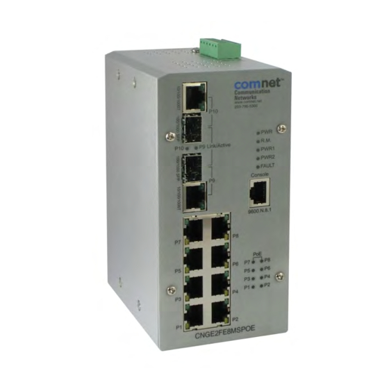
CNGE2FE8MSPOE
ENVIRONMENTALLY HARDENED MANAGED ETHERNET
SWITCH WITH (8) 10/100TX + (2) 10/100/1000TX RJ45
OR 100/1000 FX SFP PORTS
V1.04 – March 2010
CNGE2FE8MSPOE Managed Ethernet Switch provides transmission of (8)
10/100 BASE-TX and (2) 10/100/1000TX or 100/1000FX combo ports. Unlike
most Ethernet switches, these environmentally hardened units are designed
for deployment in difficult operating environments, and are available for use
with either conventional CAT-5e copper or optical transmission media. The 8
electrical ports support the 10/100 Mbps Ethernet IEEE 802.3 protocol, and
auto-negotiating and auto-MDI/MDIX features are provided for simplicity and
ease of installation. All 8 ports support IEEE.802.3af based POE. 2 ports are
10/100/1000 configurable for copper or fiber media for use with multimode
or single mode optical fiber, selected by optional SFP modules. These
network managed layer 2 switches are optically (100/1000 BASE-FX) and
electrically compatible with any IEEE 802.3 compliant Ethernet devices. Plug-
and-play design ensures ease of installation, and no electrical or optical
adjustments are ever required. The CNGE2FE8MSPOE incorporates LED
indicators for monitoring the operating status of the managed switch and
network.
Advertisement
Table of Contents

Related Manuals for Comnet CNGE2FE8MSPOE


Summary of Contents for Comnet CNGE2FE8MSPOE
- Page 1 SWITCH WITH (8) 10/100TX + (2) 10/100/1000TX RJ45 OR 100/1000 FX SFP PORTS V1.04 – March 2010 CNGE2FE8MSPOE Managed Ethernet Switch provides transmission of (8) 10/100 BASE-TX and (2) 10/100/1000TX or 100/1000FX combo ports. Unlike most Ethernet switches, these environmentally hardened units are designed for deployment in difficult operating environments, and are available for use with either conventional CAT-5e copper or optical transmission media.
-
Page 2: Fcc Warning
FCC Warning This Equipment has been tested and found to comply with the limits for a Class-A digital device, pursuant to Part 15 of the FCC rules. These limits are designed to provide reasonable protection against harmful interference in a residential installation. -
Page 3: Table Of Contents
Content Chapter 1 Introduction .......... 1 Hardware Features ........1 Software Features.......... 5 Package Contents.......... 8 Chapter 2 Hardware Description ......9 Physical Dimension........9 Front Panel............. 9 ... - Page 4 Pin Assignment ..........29 Login in the Console Interface ..... 30 CLI Management ......... 32 Commands Level ......... 32 Chapter 6 Web-Based Management....34 About Web-based Management ....34 ...
- Page 5 6.11 IP Security..........57 6.12 User Authentication........59 6.13 Port Statistics ..........60 6.14 Port Control ..........62 6.15 Port Trunk ..........64 6.15.1 Aggregator setting........64 6.15.2 Aggregator Information .......
- Page 6 6.22 IGMP Configuration ......... 100 6.23 X-Ring ............102 6.24 LLDP Configuration........104 6.25 Security—802.1X/Radius Configuration .. 105 6.25.1 System Configuration........ 105 6.25.2 Port Configuration ........107 6.25.3 Misc Configuration ........
- Page 7 VLAN Commands Set .......... 135 Spanning Tree Commands Set ......137 QOS Commands Set..........140 IGMP Commands Set .......... 140 Multicast Filtering Commands Set......141 LLDP Commands Set........... 142 Mac / Filter Table Commands Set......142 ...
-
Page 8: Chapter 1 Introduction
Chapter 1 Introduction The 8 10/100TX + 2 10/100/1000T/Mini-GBIC Combo with 8 PoE Injectors Managed Industrial Switch is a cost-effective solution and meets the high reliability requirements demanded by industrial applications. Using fiber port can extend the connection distance that increases the network elasticity and performance. Besides, the industrial switch provides the PoE function for kinds of Powered Devices to receive power as well as data over the RJ45 cable. - Page 9 Packet Buffer 1Mbits MAC Address 8K MAC address table Flash ROM 4Mbytes DRAM 32Mbytes 10/100TX: 8 x RJ45 10/100/1000T/ Mini-GBIC Combo: 2 x RJ45 + 2 x 100/1000 Connector SFP sockets RS-232 connector: RJ45 type 10Base-T: 2-pair UTP/STP Cat. 3, 4, 5/ 5E cable EIA/TIA-568 100-ohm (100m) 100Base-TX: 2-pair UTP/STP Cat.
- Page 10 Sensitivity: -36 to -32 dBm (Single mode); -34 to -30 dBm (Multi mode) RJ45 port # 1~# 8 support IEEE 802.3af End-point, PoE pin Alternative A mode. Per port provides 15.4W ability. assignment Positive (VCC+): RJ45 pin 1,2. Negative (VCC-): RJ45 pin 3,6. Protocol CSMA/CD Per unit: Power (Green), Power 1 (Green), Power 2...
- Page 11 61000-4-4, CE EN61000-4-5, CE EN61000-4-6, CE EN61000-4-8, CE EN61000-4-11, CE EN61000-4-12, CE EN61000-6-2, CE EN61000-6-4 Safety UL, cUL, CE/EN60950-1 IEC60068-2-32 (Free fall), IEC60068-2-27 (Shock), Stability Testing IEC60068-2-6 (Vibration)
-
Page 12: Software Features
1.2 Software Features Management SNMP v1 v2c, v3/ Web/Telnet/CLI RFC 1215 Trap, RFC1213 MIBII, RFC 1157 SNMP MIB, RFC 1493 SNMP MIB Bridge MIB, RFC 2674 VLAN MIB, RFC 1643 , RFC 1757, RSTP MIB, Private MIB, LLDP MIB Port Based VLAN IEEE 802.1Q Tag VLAN (256 entries)/ VLAN ID (Up to 4K, VLAN VLAN ID can be assigned from 1 to 4094.) - Page 13 Port Mirror Supports 3 mirroring types: “RX, TX and Both packet”. Supports IGMP snooping v1,v2 IGMP 256 multicast groups and IGMP query Supports 10 IP addresses that have permission to access IP Security the switch management and to prevent unauthorized intruder.
- Page 14 1. Cold start 2. Link up/down SNMP Trap 3. X-Ring topology changed 4. Authorization fail 5. PD disconnect trap-PoE port event DHCP Provides DHCP Client/ DHCP Server/ Port and IP Binding Provides DNS client feature and supports Primary and Secondary DNS server SNTP Supports SNTP to synchronize system clock in Internet Firmware Update...
-
Page 15: Package Contents
1.3 Package Contents Please refer to the package content list below to verify them against the checklist. 8 10/100TX + 2 10/100/1000T/Mini-GBIC Combo with 8 PoE Injectors Managed Industrial Switch x 1 User manual x 1 Pluggable Terminal Block x 1 ... -
Page 16: Chapter 2 Hardware Description
Chapter 2 Hardware Description In this paragraph, it will describe the Industrial switch’s hardware spec, port, cabling information, and wiring installation. 2.1 Physical Dimension 8 10/100TX w/ X-Ring Managed Industrial Switch dimension (W x D x H) is 72mm x 105mm x 152mm 2.2 Front Panel The Front Panel of the 8 10/100TX w/ X-Ring Managed Industrial Switch is shown as below:... -
Page 17: Top View
2.3 Top View The top panel of the 8 10/100TX w/ X-Ring Managed Industrial Switch has one terminal block connector of two DC power inputs and one fault alarm. Top Panel of the industrial switch... -
Page 18: Led Indicators
2.4 LED Indicators The diagnostic LEDs that provide real-time information of system and optional status are located on the front panel of the industrial switch. The following table provides the description of the LED status and their meanings for the switch. Color Status Meaning... - Page 19 (Lower LED) Off 10/100M The SFP port is linking Link/Active The port is transmitting or receiving packets (P9, P10 Green Blinks from the TX device. SFP) No device attached A network device is detected. The port is transmitting or receiving packets Green Blinking from the TX device.
-
Page 20: Chapter 3 Hardware Installation
Chapter 3 Hardware Installation In this paragraph, we will describe how to install the 8 10/100TX w/ X-Ring Managed Industrial Switch and the installation points attended to it. 3.1 Installation Steps 1. Unpack the Industrial switch 2. Check if the DIN-Rail is screwed on the Industrial switch or not. If the DIN-Rail is not screwed on the Industrial switch, please refer to DIN-Rail Mounting section for DIN-Rail installation. -
Page 21: Din-Rail Mounting
3.2 DIN-Rail Mounting The DIN-Rail is screwed on the industrial switch when out of factory. If the DIN-Rail is not screwed on the industrial switch, please see the following pictures to screw the DIN-Rail on the switch. Follow the steps below to hang the industrial switch. Back Side... - Page 23 First, insert the top of DIN-Rail into the track. Then, lightly push the DIN-Rail into the track. Check if the DIN-Rail is tightened on the track or not. To remove the industrial switch from the track, reverse above steps.
-
Page 24: Wall Mount Plate Mounting
3.3 Wall Mount Plate Mounting Follow the steps below to mount the industrial switch with wall mount plate. 1. Remove the DIN-Rail from the industrial switch; loose the screws to remove the DIN- Rail. 2. Place the wall mount plate on the rear panel of the industrial switch. 3. -
Page 25: Wiring The Power Inputs
3.4 Wiring the Power Inputs Please follow the steps below to insert the power wire. 1. Insert DC power wires into the contacts 1 and 2 for power 1, or 5 and 6 for power. 2. Tighten the wire-clamp screws for preventing the wires from loosing. [NOTE] The wire gauge for the terminal block should be in the range between 12 ~ 24 AWG. -
Page 26: Wiring The Fault Alarm Contact
3.5 Wiring the Fault Alarm Contact The fault alarm contacts are in the middle of the terminal block connector as the picture shows below. Inserting the wires, the switch will detect the fault status of the power failure, or port link failure (available for managed model) and then forms an open circuit. The following illustration shows an application example for wiring the fault alarm contacts. -
Page 27: Cabling
3.6 Cabling Use four twisted-pair, Category 5e or above cabling for RJ45 port connection. The cable between the switch and the link partner (switch, hub, workstation, etc.) must be less than 100 meters (328 ft.) long. Fiber segment using single-mode connector type must use 9/125 µm single-mode fiber cable. - Page 28 To connect the transceiver and LC cable, please follow the steps shown below: First, insert the transceiver into the SFP module. Notice that the triangle mark is the bottom of the module. Transceiver to the SFP module Transceiver Inserted Second, insert the fiber cable of LC connector into the transceiver.
- Page 29 LC connector to the transceiver...
- Page 30 To remove the LC connector from the transceiver, please follow the steps shown below: First, press the upper side of the LC connector to release from the transceiver and pull it out. Remove LC connector Second, push down the metal loop and pull the transceiver out by the plastic handle. Pull out from the transceiver...
-
Page 31: Chapter 4 Network Application
Chapter 4 Network Application This chapter provides some sample applications to help user to have more actual idea of industrial switch function application. A sample application of the industrial switch is as below:... - Page 32 The illustration below shows an example of power over Ethernet application.
-
Page 33: X-Ring Application
4.1 X-Ring Application The industrial switch supports the X-Ring protocol that can help the network system to recovery from network connection failure within 20ms or less, and make the network system more reliable. The X-Ring algorithm is similar to spanning tree protocol (STP) algorithm but its recovery time is faster than STP. -
Page 34: Coupling Ring Application
4.2 Coupling Ring Application In the network, it may have more than one X-Ring group. By using the coupling ring function, it can connect each X-Ring for the redundant backup. It can ensure the transmissions between two ring groups not to fail. The following figure is a sample of coupling ring application. -
Page 35: Dual Homing Application
4.3 Dual Homing Application Dual Homing function is to prevent the connection lose from between X-Ring group and upper level/core switch. Assign two ports to be the Dual Homing port that is backup port in the X-Ring group. The Dual Homing function only works when the X-Ring function is active. Each X-Ring group only has one Dual Homing port. -
Page 36: Chapter 5 Console Management
Chapter 5 Console Management 5.1 Connecting to the Console Port The supplied cable which one end is RS-232 connector and the other end is RJ45 connector. Attach the end of RS-232 connector to PC or terminal and the other end of RJ45 connector to the console port of the switch. -
Page 37: Login In The Console Interface
Brown/White Brown 5.3 Login in the Console Interface When the connection between Switch and PC is ready, turn on the PC and run a terminal emulation program or Hyper Terminal and configure its communication parameters to match the following default characteristics of the console port: Baud Rate: 9600 bps Data Bits: 8 Parity: none... - Page 38 Having finished the parameter settings, click ‘OK’. When the blank screen shows up, press Enter key to have the login prompt appears. Key in ‘admin’ (default value) for both User name and Password (use Enter key to switch), then press Enter and the Main Menu of console management appears.
-
Page 39: Cli Management
5.4 CLI Management The system supports the console management—CLI command. After you log in on to the system, you will see a command prompt. To enter CLI management interface, type in “enable” command. CLI command interface The following table lists the CLI commands and description. 5.5 Commands Level Access Exit... - Page 40 EXEC mode. • Display advanced function status • Save configuration Enter the To exit to Use this mode to configure privileged configure those Global command switch EXEC parameters that are Configuration while in (config)# mode, enter going to be applied to privileged exit or end your switch.
-
Page 41: Chapter 6 Web-Based Management
Chapter 6 Web-Based Management This section introduces the configuration and functions of the Web-Based management. 6.1 About Web-based Management There is an embedded HTML web site residing in flash memory on CPU board of the switch, which offers advanced management features and allows users to manage the switch from anywhere on the network through a standard browser such as Microsoft Internet Explorer. -
Page 42: System Login
6.3 System Login Launch the Internet Explorer on the PC Key in “http:// “+” the IP address of the switch”, and then Press “Enter”. The login screen will appear right after Key in the user name and password. The default user name and password are the same as ‘admin’. -
Page 43: System Information
6.4 System Information User can assign the system name, description, location and contact personnel to identify the switch. The version table below is a read-only field to show the basic information of the switch. System Name: Assign the system name of the switch (The maximum length is 64 bytes) ... -
Page 44: Ip Configuration
6.5 IP Configuration The switch is a network device which needs to be assigned an IP address for being identified on the network. Users have to decide a means of assigning IP address to the switch. DHCP Client: Enable or disable the DHCP client function. When DHCP client function is enabled, the switch will be assigned an IP address from the network DHCP server. - Page 45 IP configuration interface...
-
Page 46: Dhcp Server
6.6 DHCP Server DHCP is the abbreviation of Dynamic Host Configuration Protocol that is a protocol for assigning dynamic IP addresses to devices on a network. With dynamic addressing, a device can have a different IP address every time it connects to the network. In some systems, the device's IP address can even change while it is still connected. -
Page 47: System Configuration
6.6.1 System configuration DHCP Server: Enable or Disable the DHCP Server function. Enable—the switch will be the DHCP server on your local network. Low IP Address: Type in an IP address. Low IP address is the beginning of the dynamic IP range. -
Page 48: Client Entries
6.6.2 Client Entries When the DHCP server function is enabled, the system will collect the DHCP client information including the assigned IP address, the MAC address of the client device, the IP assigning type, status and lease time. DHCP Client Entries interface... -
Page 49: Port And Ip Bindings
6.6.3 Port and IP Bindings Assign the dynamic IP address bound with the port to the connected client. The user is allowed to fill each port column with one particular IP address. When the device is connecting to the port and asks for IP assigning, the system will assign the IP address bound with the port. -
Page 50: Tftp
6.7 TFTP It provides the functions allowing the user to update the switch firmware via the Trivial File Transfer Protocol (TFTP) server. Before updating, make sure the TFTP server is ready and the firmware image is located on the TFTP server. 6.7.1 Update Firmware ... -
Page 51: Restore Configuration
6.7.2 Restore Configuration You can restore a previous backup configuration from the TFTP server to recover the settings. Before doing that, you must locate the image file on the TFTP server first and the switch will download back the flash image. ... -
Page 52: Backup Configuration
6.7.3 Backup Configuration You can back up the current configuration from flash ROM to the TFTP server for the purpose of recovering the configuration later. It helps you to avoid wasting time on configuring the settings by backing up the configuration. ... -
Page 53: System Event Log
6.8 System Event Log This page allows the user to decide whether to send the system event log, and select the mode which the system event log will be sent to client only, server only, or both client and server. What kind of event log will be issued to the client/server depends on the selection on the Event Configuration tab. - Page 54 Syslog Configuration interface...
-
Page 55: System Event Log-Smtp Configuration
6.8.2 System Event Log—SMTP Configuration Simple Mail Transfer Protocol (SMTP) is the standard for email transmissions across the network. You can configure the SMTP server IP, mail subject, sender, mail account, password, and the recipient email addresses which the e-mail alert will send to. There are also five types of event—Device Cold Start, Authentication Failure, X-Ring Topology Change, and Port Event—available to be issued as the e-mail alert. - Page 56 SMTP Configuration interface...
-
Page 57: System Event Log-Event Configuration
6.8.3 System Event Log—Event Configuration Having ticked the Syslog/SMTP checkboxes, the event log/email alert will be sent to the system log server and the SMTP server respectively. Also, Port event log/alert (link up, link down, and both) can be sent to the system log server/SMTP server respectively by setting the trigger condition. - Page 58 Event Configuration interface...
-
Page 59: Fault Relay Alarm
6.9 Fault Relay Alarm The Fault Relay Alarm function provides the Power Failure and Port Link Down/Broken detection. With both power input 1 and power input 2 installed and the check boxes of power 1/power 2 ticked, the FAULT LED indicator will then be possible to light up when any one of the power failures occurs. -
Page 60: Sntp Configuration
6.10 SNTP Configuration SNTP (Simple Network Time Protocol) is a simplified version of NTP which is an Internet protocol used to synchronize the clocks of computers to some time reference. Because time usually just advances, the time on different node stations will be different. With the communicating programs running on those devices, it would cause time to jump forward and back, a non-desirable effect. - Page 61 EDT - Eastern Daylight EST - Eastern Standard -5 hours 7 am CDT - Central Daylight CST - Central Standard -6 hours 6 am MDT - Mountain Daylight MST - Mountain Standard -7 hours 5 am PDT - Pacific Daylight PST - Pacific Standard -8 hours ...
- Page 62 ZP6 - USSR Zone 5 +6 hours 6 pm WAST - West Australian +7 hours 7 pm Standard CCT - China Coast, +8 hours 8 pm USSR Zone 7 JST - Japan Standard, +9 hours 9 pm USSR Zone 8 EAST - East Australian Standard GST +10 hours ...
- Page 63 Daylight Saving Offset (mins): For non-US and European countries, specify the amount of time for day light savings. Please key in the valid figure in the range of minute between 0 and 720, which means you can set the offset up to 12 hours. ...
-
Page 64: Ip Security
6.11 IP Security IP security function allows the user to assign 10 specific IP addresses that have permission to manage the switch through the http and telnet services for the securing switch management. The purpose of giving the limited IP addresses permission is to allow only the authorized personnel/device can do the management task on the switch. - Page 65 IP Security interface...
-
Page 66: User Authentication
6.12 User Authentication Change web management login user name and password for the management security issue. User name: Type in the new user name (The default is ‘admin’) Password: Type in the new password (The default is ‘admin’) ... -
Page 67: Port Statistics
6.13 Port Statistics The following chart provides the current statistic information which displays the real-time packet transfer status for each port. The user might use the information to plan and implement the network, or check and find the problem when the collision or heavy traffic occurs. - Page 68 Port Statistics interface...
-
Page 69: Port Control
6.14 Port Control In Port control you can configure the settings of each port to control the connection parameters, and the status of each port is listed beneath. Port: Use the scroll bar and click on the port number to choose the port to be configured. - Page 70 Port Control interface...
-
Page 71: Port Trunk
6.15 Port Trunk Port trunking is the combination of several ports or network cables to expand the connection speed beyond the limits of any one single port or network cable. Link Aggregation Control Protocol (LACP), which is a protocol running on layer 2, provides a standardized means in accordance with IEEE 802.3ad to bundle several physical ports together to form a single logical channel. - Page 72 Select the ports to join the trunk group. The system allows a maximum of four ports to be aggregated in a trunk group. Click and the ports focused in the right side will be shifted to the left side. To remove unwanted ports, select the ports and click ...
-
Page 73: Aggregator Information
6.15.2 Aggregator Information LACP disabled Having set up the aggregator setting with LACP disabled, you will see the local static trunk group information on the tab of Aggregator Information. Assigning 2 ports to a trunk group with LACP disabled... - Page 74 Static Trunking Group information Group Key: This is a read-only column field that displays the trunk group ID. Port Member: This is a read-only column field that displays the members of this static trunk group.
- Page 75 LACP enabled Having set up the aggregator setting with LACP enabled, you will see the trunking group information between two switches on the tab of Aggregator Information. Switch 1 configuration Set System Priority of the trunk group. The default is 1. Select a trunk group ID by pull down the drop-down menu bar.
- Page 76 Switch 1 configuration interface Aggregation Information of Switch 1 Click on the tab of Aggregator Information to check the trunked group information as the illustration shown above after the two switches configured.
- Page 77 Switch 2 configuration Switch 2 configuration interface Set System Priority of the trunk group. The default is 1. Select a trunk group ID by pull down the drop-down menu bar. Enable LACP. Include the member ports by clicking the button after selecting the port number and the column field of Work Ports changes automatically.
- Page 78 Aggregation Information of Switch 2 Click on the tab of Aggregator Information to check the trunked group information as the illustration shown above after the two switches configured.
-
Page 79: State Activity
6.15.3 State Activity Having set up the LACP aggregator on the tab of Aggregator Setting, you can configure the state activity for the members of the LACP trunk group. You can tick or cancel the checkbox beside the state label. When you remove the tick mark of the port and click , the port state activity will change to Passive. - Page 80 State Activity of Switch 2...
-
Page 81: Port Mirroring
6.16 Port Mirroring The Port mirroring is a method for monitor traffic in switched networks. Traffic through ports can be monitored by one specific port, which means traffic goes in or out monitored (source) ports will be duplicated into mirror (destination) port. ... -
Page 82: Rate Limiting
6.17 Rate Limiting You can set up every port’s bandwidth rate and frame limitation type. Ingress Limit Frame type: select the frame type that wants to filter. There are four frame types for selecting: Broadcast/Multicast/Flooded Unicast Broadcast/Multicast ... - Page 83 is 10Mbps, users can set it’s effective egress rate is 1Mbps, ingress rate is 500Kbps. The switch performs the ingress rate by packet counter to meet the specified rate Ingress: Enter the port effective ingress rate (The default value is “0”). ...
-
Page 84: Vlan Configuration
6.18 VLAN configuration A Virtual LAN (VLAN) is a logical network grouping that limits the broadcast domain, which would allow you to isolate network traffic, so only the members of the same VLAN will receive traffic from the ones of the same VLAN. Basically, creating a VLAN on a switch is logically equivalent of reconnecting a group of network devices to another Layer 2 switch. -
Page 85: Port-Based Vlan
6.18.1 Port-based VLAN A port-based VLAN basically consists of its members—ports, which means the VLAN is created by grouping the selected ports. This method provides the convenience for users to configure a simple VLAN easily without complicated steps. Packets can go among only members of the same VLAN group. - Page 86 Pull down the selection item and focus on Port Based then press to set the VLAN Operation Mode in Port Based mode. Click to add a new VLAN group (The maximum VLAN groups are up to 64). VLAN—Port Based Add interface ...
- Page 87 You will see the VLAN list displays. VLAN—Port Based Edit/Delete interface to delete the VLAN. to modify group name, VLAN ID, or add/remove the members of the existing VLAN group. [NOTE] Remember to execute the “Save Configuration” action, otherwise the new configuration will lose when switch power off.
-
Page 88: Q Vlan
6.18.2 802.1Q VLAN Virtual Local Area Network (VLAN) can be implemented on the switch to logically create different broadcast domain. When the 802.1Q VLAN function is enabled, all ports on the switch belong to default VLAN of VID 1, which means they logically are regarded as members of the same broadcast domain. - Page 89 802.1Q Configuration Pull down the selection item and focus on 802.1Q then press to set the VLAN Operation Mode in 802.1Q mode. Enable GVRP Protocol: GVRP (GARP VLAN Registration Protocol) is a protocol that facilitates control of virtual local area networks (VLANs) within a larger network. GVRP conforms to the IEEE 802.1Q specification, which defines a method of tagging frames with VLAN configuration data.
- Page 90 Trunk Link: A segment which provides the link path for one or more VLAN-aware devices (switches). A Trunk Port, connected to the trunk link, has an understanding of tagged frame, which is used for the communication among VLANs across switches. Which frames of the specified VIDs will be forwarded depends on the values filled in the Tagged VID column field.
-
Page 91: Group Configuration
802.1Q VLAN interface Group Configuration Edit the existing VLAN Group. Select the VLAN group in the table list. Click... - Page 92 Group Configuration interface You can modify the VLAN group name and VLAN ID. Group Configuration interface Click...
-
Page 93: Rapid Spanning Tree
6.19 Rapid Spanning Tree The Rapid Spanning Tree Protocol (RSTP) is an evolution of the Spanning Tree Protocol and provides for faster spanning tree convergence after a topology change. The system also supports STP and the system will auto-detect the connected device that is running STP or RSTP protocol. - Page 94 RSTP System Configuration interface...
-
Page 95: Port Configuration
6.19.2 Port Configuration This web page provides the port configuration interface for RSTP. You can assign higher or lower priority to each port. Rapid spanning tree will have the port with the higher priority in forwarding state and block other ports to make certain that there is no loop in the LAN. ... - Page 96 RSTP Port Configuration interface...
-
Page 97: Snmp Configuration
6.20 SNMP Configuration Simple Network Management Protocol (SNMP) is the protocol developed to manage nodes (servers, workstations, routers, switches and hubs etc.) on an IP network. SNMP enables network administrators to manage network performance, find and solve network problems, and plan for network growth. Network management systems learn of problems by receiving traps or change notices from network devices implementing SNMP. - Page 98 SNMP System Configuration interface...
-
Page 99: Trap Configuration
6.20.2 Trap Configuration A trap manager is a management station that receives the trap messages generated by the switch. If no trap manager is defined, no traps will be issued. To define a management station as a trap manager, assign an IP address, enter the SNMP community strings, and select the SNMP trap version. -
Page 100: Snmpv3 Configuration
6.20.3 SNMPV3 Configuration Configure the SNMP V3 function. Context Table Configure SNMP v3 context table. Assign the context name of context table. Click to add context name. User Table Configure SNMP v3 user table.. User ID: set up the user name. ... - Page 101 SNMP V3 configuration interface Access Table Configure SNMP v3 access table. Context Prefix: set up the context name. Group Name: set up the group. Security Level: select the access level. Context Match Rule: select the context match rule. ...
- Page 102 MIBview Table Configure MIB view table. ViewName: set up the name. Sub-Oid Tree: fill the Sub OID. Type: select the type – exclude or included. Click to add context name. Click to remove unwanted context name. ...
-
Page 103: Qos Configuration
6.21 QoS Configuration Quality of Service (QoS) is the ability to provide different priority to different applications, users or data flows, or to guarantee a certain level of performance to a data flow. QoS guarantees are important if the network capacity is insufficient, especially for real-time streaming multimedia applications such as voice over IP or Video Teleconferencing, since these often require fixed bit rate and are delay sensitive, and in networks where the capacity is a limited resource, for example in cellular data communication. - Page 104 QoS Configuration interface...
-
Page 105: Port-Based Priority
6.21.2 Port-based Priority Configure the priority level for each port. With the drop-down selection item of Priority Type above being selected as Port-based, this control item will then be available to set the queuing policy for each port. Port x: Each port has 4 priority levels—High, Middle, Low, and Lowest—to be chosen. ... - Page 106 When the IP packet is received, the system will check the TOS level value in the IP packet that has received. For example, the user sets the TOS level 25 as high, the system will check the TOS value of the received IP packet. If the TOS value of received IP packet is 25 (priority = high), and then the packet priority will have highest priority.
-
Page 107: Igmp Configuration
6.22 IGMP Configuration The Internet Group Management Protocol (IGMP) is an internal protocol of the Internet Protocol (IP) suite. IP manages multicast traffic by using switches, routers, and hosts that support IGMP. Enabling IGMP allows the ports to detect IGMP queries, report packets, and manage IP multicast traffic through the switch. - Page 108 IGMP Configuration interface...
-
Page 109: X-Ring
6.23 X-Ring X-Ring provides a faster redundant recovery than Spanning Tree topology. The action is similar to STP or RSTP, but the algorithms between them are not the same. In the X-Ring topology, every switch should be enabled with X-Ring function and two ports should be assigned as the member ports in the ring. - Page 110 Enable Couple Ring string label. Couple Port: Assign the member port which is connected to the other ring group. Control Port: When the Enable Couple Ring checkbox is ticked, you have to assign the control port to form a couple-ring group between the two X-rings. ...
-
Page 111: Lldp Configuration
6.24 LLDP Configuration Link Layer Discovery Protocol (LLDP) is defined in the IEEE 802.1AB, it is an emerging standard which provides a solution for the configuration issues caused by expanding LANs. LLDP specifically defines a standard method for Ethernet network devices such as switches, routers and wireless LAN access points to advertise information about themselves to other nodes on the network and store the information they discover. -
Page 112: Security-802.1X/Radius Configuration
6.25 Security—802.1X/Radius Configuration 802.1x is an IEEE authentication specification which prevents the client from accessing a wireless access point or wired switch until it provides authority, like the user name and password that are verified by an authentication server (such as RADIUS server). 6.25.1 System Configuration After enabling the IEEE 802.1X function, you can configure the parameters of this function. - Page 113 802.1x System Configuration interface...
-
Page 114: Port Configuration
6.25.2 Port Configuration You can configure the 802.1x authentication state for each port. The state provides Disable, Accept, Reject, and Authorize. Reject: The specified port is required to be held in the unauthorized state. Accept: The specified port is required to be held in the authorized state. ... - Page 115 802.1x Per Port Setting interface...
-
Page 116: Misc Configuration
6.25.3 Misc Configuration Quiet Period: Set the period which the port doesn’t try to acquire a supplicant. TX Period: Set the period the port waits for retransmit next EAPOL PDU during an authentication session. Supplicant Timeout: Set the period of time the switch waits for a supplicant response to an EAP request. -
Page 117: Mac Address Table
6.26 MAC Address Table Use the MAC address table to ensure the port security. 6.26.1 Static MAC Address You can add a static MAC address that remains in the switch's address table regardless of whether the device is physically connected to the switch. This saves the switch from having to re-learn a device's MAC address when the disconnected or powered-off device is active on the network again. - Page 118 Static MAC Addresses interface...
-
Page 119: Mac Filtering
6.26.2 MAC Filtering By filtering MAC address, the switch can easily filter the pre-configured MAC address and reduce the un-safety. You can add and delete filtering MAC address. MAC Filtering interface MAC Address: Enter the MAC address that you want to filter. ... -
Page 120: All Mac Addresses
6.26.3 All MAC Addresses You can view all of the MAC addresses learned by the selected port. Select the port number. The selected port of static & dynamic MAC address information will be displayed in here. Click to clear the dynamic MAC addresses information of the current port shown on the screen. -
Page 121: Mac Address Table-Multicast Filtering
6.26.4 MAC Address Table—Multicast Filtering Multicasts are similar to broadcasts, they are sent to all end stations on a LAN or VLAN. Multicast filtering is the function, which end stations can receive the multicast traffic if the connected ports had been included in the specific multicast groups. With multicast filtering, network devices only forward multicast traffic to the ports that are connected to the registered end stations. - Page 122 Multicast Filtering interface...
-
Page 123: Power Over Ethernet
6.27 Power over Ethernet This segment shows the Power over Ethernet function. PoE Status Actual Power Consumption: This column shows the real-time total power consumption. Main Supply Voltage: This column shows the output voltage of the system for PoE ports. - Page 124 subtracted from the pre-capacitance voltage to get a charge rate. If this charge rate is within the window of the PD signatures, the device is considered to be discovered. And then, click to carry into effect. Port: The index of PoE ports. ...
-
Page 125: Factory Default
6.28 Factory Default Reset switch to default configuration. Click to reset all configurations to the default value. Factory Default interface... -
Page 126: Save Configuration
6.29 Save Configuration Save all configurations that you have made in the system. To ensure the all configuration will be saved. Click to save the all configuration to the flash memory. Save Configuration interface... -
Page 127: System Reboot
6.30 System Reboot Reboot the switch in software reset. Click to reboot the system. System Reboot interface... -
Page 128: Troubles Shooting
Troubles shooting Verify that is using the right power cord/adapter (DC 24-48V), please don’t use the power adapter with DC output higher than 48V, or it may damage this device. Select the proper UTP/STP cable to construct the user network. Use unshielded twisted-pair (UTP) or shield twisted-pair (STP) cable for RJ45 connections that depend on the connector type the switch equipped: 100 Category 3, 4 or 5 cable for 10Mbps... -
Page 129: Appendix A-Rj45 Pin Assignment
Appendix A—RJ45 Pin Assignment RJ45 Pin Assignments The UTP/STP ports will automatically sense for Fast Ethernet (10Base-T/100Base-TX connections), or Gigabit Ethernet (10Base-T/100Base-TX/1000Base-T connections). Auto MDI/MDIX means that the switch can connect to another switch or workstation without changing straight through or crossover cabling. See the figures below for straight through and crossover cable schematic. - Page 130 Transmit Data plus (TD+) Receive Data plus (RD+) Transmit Data minus (TD-) Receive Data minus (RD-) 10/100Base-TX Cable Schematic The following two figures show the 10/100Base-TX cable schematic. Straight-through cable schematic Cross over cable schematic 10/100/1000Base-TX Pin outs The following figure shows the 10/100/1000 Ethernet RJ45 pin outs.
- Page 131 10/100/1000Base-TX Cable Schematic Straight through cables schematic...
- Page 132 Cross over cables schematic...
-
Page 133: Rj45 Pin Assignment Of Poe
RJ45 Pin Assignment of PoE With 100BASE-TX/10BASE-T cable, pins 1 and 2 are used for transmitting data, and pins 3 and 6 for receiving data; pins 4, 5, 7 and 8 are used for power supplying. Pin out of Cisco non-802.3af standard PD Signal VCC - VCC -... - Page 134 Pin out of PoE Endspan Hub/Switch Signal / Name TX+/VCC+ TX-/VCC+ TX+/VCC- TX-/VCC- Note ‘+’ and ‘-‘ signs represent the polarity of the wires that make up each wire pair. Before you power PD, please check the RJ45 connector pin assignment follow IEEE802.3af standard;...
-
Page 135: Appendix B-Command Sets
Appendix B—Command Sets Commands Set List User EXEC Privileged EXEC Global configuration VLAN database Interface configuration System Commands Set Netstar Commands Level Description Example show config Show switch switch>show config configuration show terminal Show console switch#show terminal information write memory Save user switch#write memory configuration into... - Page 136 [Ip-address] [Subnet- address of switch 192.168.1.1 255.255.255.0 mask] [Gateway] 192.168.1.254 ip dhcp Enable DHCP client switch(config)#ip dhcp function of switch show ip Show IP information of switch#show ip switch no ip dhcp Disable DHCP client switch(config)#no ip dhcp function of switch reload Halt and perform a cold switch(config)#reload...
- Page 137 [Hours] (in hour) leasetime 1 dhcpserver ipbinding Set static IP for DHCP switch(config)#interface [IP address] clients by port fastEthernet 2 switch(config)#dhcpserver ipbinding 192.168.1.1 show dhcpserver Show configuration of switch#show dhcpserver configuration DHCP server configuration show dhcpserver clients Show client entries of switch#show dhcpserver clients DHCP server show dhcpserver ip-...
-
Page 138: Port Commands Set
telnet server Port Commands Set Netstar Commands Level Description Example interface fastEthernet Choose the port for switch(config)#interface [Portid] modification. fastEthernet 2 duplex Use the duplex switch(config)#interface [full | half] configuration fastEthernet 2 command to specify switch(config-if)#duplex full the duplex mode of operation for Fast Ethernet. - Page 139 bandwidth type all Set interface ingress switch(config)#interface limit frame type to fastEthernet 2 “accept all frame” switch(config-if)#bandwidth type bandwidth type Set interface ingress switch(config)#interface broadcast-multicast- limit frame type to fastEthernet 2 flooded-unicast “accept broadcast, switch(config-if)#bandwidth type multicast, and flooded broadcast-multicast-flooded- unicast frame”...
- Page 140 and zero means no limit. show bandwidth Show interfaces switch(config)#interface bandwidth control fastEthernet 2 switch(config-if)#show bandwidth state Use the state interface switch(config)#interface [Enable | Disable] configuration fastEthernet 2 command to specify switch(config-if)#state Disable the state mode of operation for Ethernet ports.
-
Page 141: Trunk Commands Set
Trunk Commands Set Netstar Commands Level Description Example aggregator priority Set port group system switch(config)#aggregator priority [1~65535] priority aggregator activityport Set activity port switch(config)#aggregator [Group ID] activityport 2 [Port Numbers] aggregator group Assign a trunk group switch(config)#aggregator group [GroupID] [Port-list] with LACP active. -
Page 142: Vlan Commands Set
comma(ex.2, 3, 6) show aggregator Show the information switch#show aggregator 1 of trunk group switch#show aggregator 2 switch#show aggregator 3 no aggregator lacp Disable the LACP switch(config)#no aggreator lacp [GroupID] function of trunk group no aggregator group Remove a trunk group switch(config)#no aggreator [GroupID] group 2 VLAN Commands Set... - Page 143 port [PortNumbers] show vlan [GroupID] Show VLAN switch(vlan)#show vlan 23 information show vlan no vlan group Delete port base switch(vlan)#no vlan group 2 [GroupID] group ID IEEE 802.1Q VLAN vlan 8021q name Change the name of switch(vlan)#vlan 8021q name [GroupName] VLAN group, if the test vid 22 [VID]...
-
Page 144: Spanning Tree Commands Set
[PortNumber] VLAN by trunk group trunk-link tag 2,3,6,99 trunk-link tag [TaggedVID List] switch(vlan)#vlan 8021q trunk 3 trunk-link tag 3-20 vlan 8021q trunk Assign a hybrid link for switch(vlan)#vlan 8021q trunk 3 [PortNumber] VLAN by trunk group hybrid-link untag 4 tag 3,6,8 hybrid-link untag [UntaggedVID] switch(vlan)#vlan 8021q trunk 3... - Page 145 protocol data unit (BPDU) message from the root switch within this interval, it recomputed the Spanning Tree Protocol (STP) topology. spanning-tree hello- Use the spanning-tree switch(config)#spanning-tree time [seconds] hello-time global hello-time 3 configuration command to specify the interval between hello bridge protocol data units (BPDUs).
- Page 146 command to set the path cost for Spanning Tree Protocol (STP) calculations. In the event of a loop, spanning tree considers the path cost when selecting an interface to place into the forwarding state. stp-path-priority Use the spanning-tree switch(config)#interface [Port Priority] port-priority interface fastEthernet 2 configuration...
-
Page 147: Qos Commands Set
interface. switch(config-if)#stp-admin-non- stp False show spanning-tree Displays a summary of switch>show spanning-tree the spanning-tree states. no spanning-tree Disable spanning-tree. switch(config)#no spanning-tree QOS Commands Set Netstar Commands Level Description Example qos policy Select QOS policy switch(config)#qos policy [weighted-fair|strict] scheduling weighted-fair qos prioritytype Setting of QOS priority switch(config)#qos prioritytype [port-based|cos-... -
Page 148: Multicast Filtering Commands Set
igmp enable Enable IGMP switch(config)#igmp enable snooping function Igmp query auto Set IGMP query to switch(config)#igmp query auto auto mode Igmp query force Set IGMP query to switch(config)#igmp query force force mode igmp unregister flooding Set unregister stream switch(config)#igmp unregister flooding flooding igmp unregister... -
Page 149: Lldp Commands Set
LLDP Commands Set Netstar Commands Level Description Example lldp enable Enable LLDP function switch(config)#lldp enable lldp interval [Time sec] Configure LLDP switch(config)#lldp interval 20 interval Mac / Filter Table Commands Set Netstar Commands Level Description Example mac-address-table static Configure MAC Switch(config)#interface hwaddr address table of... -
Page 150: Snmp Commands Set
no mac-address-table Remove dynamic switch(config)#no mac-address- entry of MAC address table table SNMP Commands Set Netstar Commands Level Description Example snmp system-name Set SNMP agent switch(config)#snmp system- [System Name] system name name l2switch snmp system-location Set SNMP agent switch(config)#snmp system- [System Location] system location location lab... - Page 151 [Group Name] Privacy password password could be empty. [Authentication Password] [Privacy Password] snmpv3 access context- Configure the access switch(config)#snmpv3 access name [Context Name ] table of SNMPV3 context-name Test group G1 group agent security-level AuthPriv [Group Name ] match-rule Exact views V1 V1 V1 security-level [NoAuthNoPriv|AuthNoP riv|AuthPriv]...
-
Page 152: Port Mirroring Commands Set
[User Name] user of SNMPv3 Test agent. no snmpv3 access Remove specified Switch(config)#no snmpv3 context-name [Context access table of access context-name Test group Name ] SNMPv3 agent. G1 security-level AuthPr group iv match-rule Exact views V1 V1 [Group Name ] security-level [NoAuthNoPriv|AuthNoP riv|AuthPriv]... -
Page 153: Commands Set
port of monitor function monitor tx [Port ID] Set TX destination switch(config)#monitor tx 3 port of monitor function show monitor Show port monitor switch#show monitor information show monitor Show port monitor switch(config)#interface information fastEthernet 2 switch(config-if)#show monitor no monitor Disable source port of switch(config)#interface monitor function fastEthernet 2... - Page 154 8021x system Use the 802.1x switch(config)# 8021x system accountport system account port accountport 1813 [port ID] global configuration command to change the accounting port 8021x system sharedkey Use the 802.1x Switch(config)# 8021x system [ID] system share key sharedkey 123456 global configuration command to change the shared key value.
-
Page 155: Tftp Commands Set
8021x misc Use the 802.1x misc Switch(config)#8021x misc servertimeout [sec.] server timeout global servertimeout 20 configuration command to set the server timeout. 8021x misc maxrequest Use the 802.1x misc Switch(config)# 8021x misc [number] max request global maxrequest 3 configuration command to set the MAX requests. -
Page 156: Systemlog, Smtp And Event Commands Set
backup Save configuration to Switch(config)#backup flash:backup_cfg TFTP and need to flash:backup_cfg specify the IP of TFTP server and the file name of image. restore Get configuration from Switch(config)#restore flash:restore_cfg TFTP server and need to flash:restore_cfg specify the IP of TFTP server and the file name of image. - Page 157 [IP address] server IP 192.168.1.5 smtp sender Configure sender of switch(config)#smtp snder [sendername] mail aaa@bbb.com smtp authentication Enable SMTP switch(config)#smtp authentication authentication smtp account Configure switch(config)#smtp account [account] authentication account John smtp password Configure switch(config)#smtp password [password] authentication 1234 password smtp rcptemail Configure Rcpt e-mail switch(config)#smtp rcptemail 1...
-
Page 158: Fault Relay Alarm Commands Set
Down|Both] switch(config-if)#event smtp both show event Show event selection switch#show event no event device-cold- Disable cold start switch(config)#no event device- start event type cold-start no event authentication- Disable Authentication switch(config)#no event failure failure event typ authentication-failure no event ring-topology- Disable X-ring switch(config)#no event ring- change topology changed... -
Page 159: Sntp Commands Set
SNTP Commands Set Netstar Commands Level Description Example sntp enable Enable SNTP function switch(config)#sntp enable sntp daylight Enable daylight saving switch(config)#sntp daylight time, if SNTP function is inactive, this command can’t be applied. sntp daylight-period Set period of daylight switch(config)# sntp daylight- [Start time] [End time] saving time, if SNTP period 20060101-01:01... -
Page 160: X-Ring Commands Set
number sntp sync-interval Set synchronization switch(config)#sntp sync-interval [Secs] interval show sntp Show SNTP switch#show sntp information show sntp timezone Show index number of switch#show sntp timezone time zone list no sntp Disable SNTP function switch(config)#no sntp no sntp daylight Disable daylight switch(config)#no sntp daylight saving time X-ring Commands Set... -
Page 161: Poe Commands Set
no ring couplering Disable couple ring switch(config)# no ring couplering no ring dualhoming Disable dual homing switch(config)# no ring dualhoming PoE Commands Set Netstar Commands Level Description Example Enter POE configure switch#poe mode system knockoff- Set PoE system Port switch(poe)# system knockoff- Knockoff Disabled disabled disable disabled... - Page 162 ComNet Customer Service Customer Care is ComNet Technology’s global service center, where our professional staff are ready to answer your questions at any time. Email address of ComNet Global Service Center: customercare@ComNet.net Communication Networks World Headquarters ComNet Europe Ltd 3 Corporate Drive...
Need help?
Do you have a question about the CNGE2FE8MSPOE and is the answer not in the manual?
Questions and answers