Table of Contents
Advertisement
Quick Links
INSTALLATION AND OPERATION MANUAL
CWGE9MS
COMMERCIAL GRADE 9 PORT GIGABIT MANAGED ETHERNET SWITCH
WITH (7) 10/100/1000TX + (2) 1000FX SFP
OR 10/100/1000TX PORTS
V1.02 – October 2010
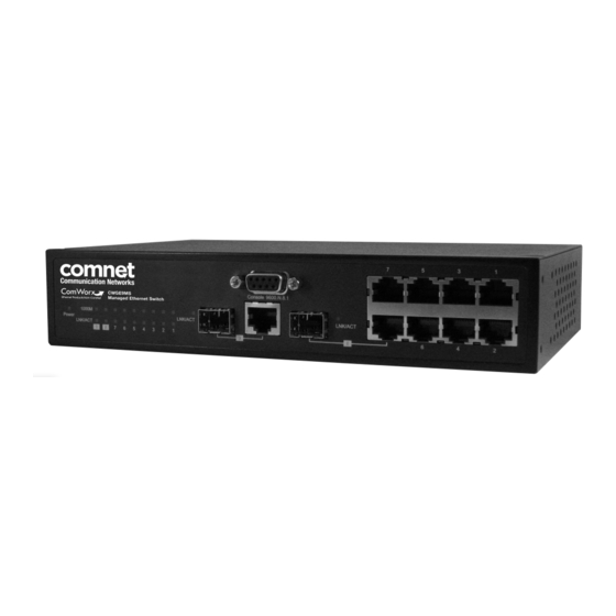
The ComNet™ CWGE9MS Managed Ethernet Switch provides transmission of (7) 10/100/1000 BASE-TX and
(2) 1000FXcombo ports. These units are available for use with either conventional CAT-5e copper or optical
transmission media. Ports 1 – 7 support the 10/100/1000 Mbps Ethernet IEEE 802.3 protocol, and
auto-negotiating and auto-MDI/MDIX features are provided for simplicity and ease of installation. Ports 8 – 9
are 10/100/1000 configurable for copper or 1000 fiber media for use with multimode or single mode optical
fiber without need for configuration, selected by optional SFP modules. These network managed layer 2
switches are optically and electrically compatible with any IEEE 802.3 compliant Ethernet devices.
Plug-and-play design ensures ease of installation, and no electrical or optical adjustments are ever required.
The CWGE9MS incorporates LED indicators for monitoring the operating status of the managed switch and
network.
Advertisement
Table of Contents

Related Manuals for Comnet CWGE9MS


Summary of Contents for Comnet CWGE9MS
- Page 1 IEEE 802.3 compliant Ethernet devices. Plug-and-play design ensures ease of installation, and no electrical or optical adjustments are ever required. The CWGE9MS incorporates LED indicators for monitoring the operating status of the managed switch and network.
-
Page 2: Fcc Warning
FCC Warning This Equipment has been tested and found to comply with the limits for a Class-A digital device, pursuant to Part 15 of the FCC rules. These limits are designed to provide reasonable protection against harmful interference in a residential installation. This equipment generates uses and can radiate radio frequency energy and, if not installed and used in accordance with the instructions, may cause harmful interference to radio communications. -
Page 3: Table Of Contents
Content Chapter 1 Introduction.....................6 1.1 Hardware Features ...................... 6 1.2 Software Feature......................8 1.3 Package Contents...................... 10 Chapter 2 Hardware Description ................11 2.1 Physical Dimension....................11 2.2 Front Panel......................... 11 2.3 Rear Panel ......................... 12 2.4 LED Indicators...................... - Page 4 6.6.2 Client Entries....................29 6.6.3 Port and IP Bindings ..................29 6.7 TFTP .......................... 30 6.7.1 Update Firmware ..................... 30 6.7.2 Restore Configuration ..................30 6.7.3 Backup Configuration..................31 6.8 System Event Log ...................... 32 6.8.1 Syslog Configuration..................
- Page 5 6.20 QoS Configuration....................69 6.20.1 QoS Policy and Priority Type ................. 69 6.20.2 Port-based Priority ..................70 6.20.3 COS Configuration..................70 6.20.3 TOS Configuration ..................71 6.21 IGMP Configuration....................72 6.22 X-Ring ........................73 6.23 LLDP ........................
- Page 6 Port Mirroring Commands Set..................107 802.1x Commands Set....................108 TFTP Commands Set ....................111 SystemLog, SMTP and Event Commands Set .............. 111 SNTP Commands Set....................114 X-ring Commands Set....................116 ...
-
Page 7: Chapter 1 Introduction
Chapter 1 Introduction The CWGE9MS managed Ethernet switch is a multi-port switch that can be used to build high-performance switched workgroup networks. It provides wire-speed, Fast Ethernet switching function that allows for a high-performance, low-cost connection. The switch features a store-and-forward switching and it can auto-learn and store source address on an 8K-entry MAC address table. - Page 8 10/100/1000TX: 7 x RJ45 with Auto MDI/MDI-X function Connector Gigabit fiber: 2 x Mini-GBIC socket Console port: RS-232 connector Store and forward switch architecture. 18Gbps Switch architecture system backplane. System throughput up to 26.7Mbps. Packet buffer 1Mbits for packet buffer One RS-232 DB-9 Female connector for switch RS-232 connector management...
-
Page 9: Software Feature
1.2 Software Feature Management SNMP v1 v2c, v3/ Web/Telnet/CLI Management Port Based VLAN IEEE 802.1Q Tag VLAN (256 entries)/ VLAN ID (Up to VLAN 4K, VLAN ID can be assigned from 1 to 4094.) GVRP (256 Groups) Port Trunk with LACP Port Trunk: 4 Trunk groups/Maximum 4 trunk LACP members... - Page 10 Support IGMP snooping v1,v2 IGMP 256 multicast groups and IGMP query Provide 10 IP addresses that have permission to access IP Security the switch management and to prevent unauthorized intruder Support IEEE802.1x User-Authentication and can report to RADIUS server. Reject Login Security Accept Authorize...
-
Page 11: Package Contents
Support text format configuration file for system quick upload and installation download 1.3 Package Contents Unpack the contents of the CWGE9MS managed Ethernet switch and verify them against the checklist below. CWGE9MS managed Ethernet switch Power Cord Four Rubber Feet... -
Page 12: Chapter 2 Hardware Description
140mm(D) x 43mm(H) 2.2 Front Panel The front panel of the CWGE9MS managed Ethernet switch consists of 7x auto-sensing 10/100/1000Mbps Ethernet RJ45 ports (automatic MDI/MDIX), 2 SFP/Giga copper combo ports, and the LED indicators are also located on the front panel of the switch. -
Page 13: Rear Panel
2.3 Rear Panel The 3-pronged power plug are located at the rear panel of the CWGE9MS managed Ethernet switch as shown in figure. The switch will work with AC in the range 100-240V AC, 50-60Hz. -
Page 14: Led Indicators
2.4 LED Indicators The following table provides descriptions of the LED statuses and meaning. They provide a real-time indication of systematic operation status. Status Description Power Green Power On Yellow The port is operating at the speed of 1000Mbps. Amber The port is operating at the speed of 100Mbps. -
Page 15: Chapter 3 Hardware Installation
Chapter 3 Hardware Installation 3.1 Desktop Installation Set the switch on a sufficiently large flat space with a power outlet nearby. The surface where you put your Switch should be clean, smooth, level, and sturdy. Make sure there is enough clearance around the Switch to allow attachment of cables, power cord and air circulation. -
Page 16: Chapter 4 Network Application
4.1 Desktop Application The CWGE9MS managed Ethernet switch is designed to be a desktop size switch that is an ideal solution for small workgroup. The switch can be used as a standalone switch to which personal computers, server, printer server are directly connected to form small workgroup. -
Page 17: X-Ring Application
You can use any of the RJ45 port of the CWGE9MS managed Ethernet switch to connect with another Switch or Hub to interconnect each of your small-switched workgroups to form a larger switched network. - Page 18 [NOTE] When the X-Ring function is enabled, the user must disable the RSTP. The X-Ring function and RSTP function cannot operate simultaneously. With X-Ring topology, every switch enables the X-Ring function and assigns two member ports in the ring. Only one switch in the X-Ring group would be the backup switch with one of the two member ports’...
-
Page 19: Coupling Ring Application
network detection of the failed link’s activation of the master’s backup link and address table. If the failed link is restored, the ring slaves will alert the ringmaster to restore normal operation by disabling the backup link on the network in less than 300ms. 4.4 Coupling Ring Application Within the network there may be more than one X-Ring group. -
Page 21: Chapter 5 Console Management
Chapter 5 Console Management 5.1 Connecting to the Console Port Use the supplied RS-232 cable to connect a terminal or PC to the console port. The terminal or PC to be connected must support the terminal emulation program. Connecting the switch to a terminal via RS-232 cable 5.2 Login in the Console Interface When the connection between Switch and PC is ready, turn on the PC and run a terminal emulation program or Hyper Terminal and configure its communication parameters to... - Page 22 The settings of communication parameters After finished the parameter settings, select “OK“. When the blank screen shows up, press Enter key to bring out the login prompt. Key in the “admin“ (default value) for the both User name and Password (use Enter key to switch), then press Enter key and the Main Menu of console management appears.
-
Page 23: Cli Management
5.3 CLI Management The system supports two types of console management – CLI command. After you login to the system, you will see a command prompt. To enter CLI management interface, enter “enable” command. The following table lists the CLI commands and description. Commands Level Modes Access Method... - Page 24 VLAN Enter the vlan switch To exit to Use this mode to configure database database (vlan)# user EXEC VLAN-specific parameters. command while mode, enter in privileged exit. EXEC mode. Interface Enter the switch To exit to Use this mode to configure configuration interface (config-if)#...
-
Page 25: Chapter 6 Web-Based Management
Chapter 6 Web-Based Management This section introduces the configuration and functions of the Web-based management. 6.1 About Web-based Management Inside the CPU board of the switch exists an embedded HTML web site residing in flash memory. It offers advanced management features and allow users to manage the switch from anywhere on the network through a standard browser such as Microsoft Internet Explorer. -
Page 26: System Login
User Name: admin Password: admin 6.3 System Login Launch the Internet Explorer on the PC Key in “http:// “+” the IP address of the switch”, and then Press “Enter”. Uniform Resource Locator The login screen appears right after. Key in the user name and password. The default user name and password are the same as ‘admin’... -
Page 27: System Information
6.4 System Information Assign the system name and location and view the system information. System Name: Assign the system name of the switch (The maximum length is 64 bytes) System Description: Describes the switch. System Location: Assign the switch physical location (The maximum length is 64 bytes). -
Page 28: Dhcp Server
Subnet Mask: Assign the subnet mask to the IP address. If DHCP client function is enabled, and then the user does not need to assign the subnet mask. Gateway: Assign the network gateway for the industrial switch. The default gateway is 192.168.10.254. -
Page 29: System Configuration
6.6.1 System configuration DHCP Server: Enable or Disable the DHCP Server function. Enable—the switch will be the DHCP server on your local network. Low IP Address: Type in an IP address. Low IP address is the beginning of the dynamic IP range. For example, dynamic IP is in the range between 192.168.1.100 ~ 192.168.1.200. -
Page 30: Client Entries
6.6.2 Client Entries When the DHCP server function is active, the system will collect the DHCP client information and displays it at this tab. DHCP Client Entries interface 6.6.3 Port and IP Bindings Assign the dynamic IP address to the port. When the device is connecting to the port and asks for IP assigning, the system will assign the IP address that has been assigned before to the connected device. -
Page 31: Tftp
6.7 TFTP 6.7.1 Update Firmware It provides the functions that allow user to update the switch firmware. Before updating, make sure the TFTP server is ready and the firmware image is located on the TFTP server. TFTP Server IP Address: Type in your TFTP server IP. Firmware File Name: Type in the name of firmware image. -
Page 32: Backup Configuration
Restore Configuration interface 6.7.3 Backup Configuration You can save the current configuration from flash ROM to TFTP server for restoring later. TFTP Server IP Address: Type in the TFTP server IP. Backup File Name: Type in the file name. Select Backup Configuration interface... -
Page 33: System Event Log
6.8 System Event Log 6.8.1 Syslog Configuration Configure the system event mode to collect system log. Syslog Client Mode: Select the system log mode—Client Only, Server Only, or Both. System Log Server IP Address: Assign the system log server IP. When Syslog Client Mode is set as Client Only, the system event log will only be reserved in the switch’s RAM until next reboot. -
Page 34: Smtp Configuration
Syslog Configuration interface 6.8.2 SMTP Configuration You can set up the mail server IP, mail account, password, and forwarded email account for receiving the event alert. Email Alert: Enable or disable the email alert function. SMTP Server IP: Set up the mail server IP address (when Email Alert enabled, this function will then be available). - Page 35 Authentication: Select the checkbox to enable this function, configuring the email account and password for authentication (when Email Alert enabled, this function will then be available). Mail Account: Set up the email account, e.g. johnadmin, to receive the alert. It must be an existing email account on the mail server, which you had set up in SMTP Server IP Address column.
-
Page 36: Event Configuration
6.8.3 Event Configuration When the Syslog/SMTP checkbox is marked, the event log will be sent to system log server/SMTP server. Also, per port log (link up, link down, and both) events can be sent to the system log server/SMTP server with the respective checkbox selected. After configuring, select to have the setting taken effect. - Page 37 Event Configuration interface...
-
Page 38: Sntp Configuration
6.9 SNTP Configuration You can configure the SNTP (Simple Network Time Protocol) settings. The SNTP allows you to synchronize switch clocks in the Internet. SNTP Client: Enable/disable SNTP function to get the time from the SNTP server. Daylight Saving Time: Enable/disable daylight saving time function. When daylight saving time is enabled, you need to configure the daylight saving time period. - Page 39 CET - Central European FWT - French Winter MET - Middle European +1 hour 1 pm MEWT - Middle European Winter SWT - Swedish Winter EET - Eastern European, USSR +2 hours 2 pm Zone 1 BT - Baghdad, USSR Zone 2 +3 hours 3 pm ZP4 - USSR Zone 3...
-
Page 40: Ip Security
Select SNTP Configuration interface 6.10 IP Security The IP security function allows the user to assign 10 specific IP addresses that have permission to access the switch through the web browser for the securing switch management. IP Security Mode: When this option is in Enable mode, the Enable HTTP Server and Enable Telnet Server checkboxes will then be available. - Page 41 And then, select button to apply the configuration. [NOTE] Remember to execute the “Save Configuration” action, otherwise the new configuration will lose when the switch powers off. IP Security interface...
-
Page 42: User Authentication
6.11 User Authentication Change web management login user name and password for the management security issue. User name: Type in the new user name (The default is ‘admin’) Password: Type in the new password (The default is ‘admin’) Confirm password: Re-type the new password And then, select User Authentication interface... -
Page 43: Port Statistics
6.12 Port Statistics The following information provides the current port statistic information. Port: Displays the port number. Type: Displays the media type of the port. Link: The status of linking—‘Up’ or ‘Down’. State: The user can set the state of the port as ‘Enable’ or ‘Disable’ via Port Control. When the state is disabled, the port will not transmit or receive any packet. -
Page 44: Port Control
6.13 Port Control In Port control, you can view and set the operation mode of each port. Port: Select the port that you want to configure. State: Current port status. The port can be set to disable or enable mode. If the port state is set as ‘Disable’, it will not receive or transmit any packet. -
Page 45: Port Trunk
Port Control interface 6.14 Port Trunk The Link Aggregation Control Protocol (LACP) provides a standardized means for exchanging information between Partner Systems on a link to allow their Link Aggregation Control instances to reach agreement on the identity of the Link Aggregation Group to which the link belongs, move the link to that Link Aggregation Group, and enable its transmission and reception functions in an orderly manner. -
Page 46: Aggregator Setting
6.14.1 Aggregator setting System Priority: A value that is used to identify the active LACP. The switch with the lowest value has the highest priority and is selected as the active LACP. Group ID: There are four trunk groups to be selected. Choose the "Group ID" and select button. - Page 47 button to delete Trunk Group. Select the Group ID and select button. Port Trunk—Aggregator Setting interface (four ports are added to the left field with LACP enabled)
-
Page 48: Aggregator Information
6.14.2 Aggregator Information When you have setup the aggregator setting with LACP disabled, you will see the local static trunk group information here. Group Key: Displays the trunk group ID. Port Member: Displays the members of this static trunk group. Port Trunk—Aggregator Setting interface (two ports are added to the left field with LACP disable) -
Page 49: State Activity
Port Trunk – Aggregator Information interface 6.14.3 State Activity Having set up the LACP aggregator on the tab of Aggregator Setting, you can configure the state activity for the members of the LACP trunk group. You can select or cancel the checkbox beside the state display. - Page 50 Port Trunk – State Activity interface...
-
Page 51: Port Mirroring
6.15 Port Mirroring The Port mirroring is a method for monitoring traffic in switched networks. Traffic through ports can be monitored by one specific port which means traffic goes in or out monitored (source) ports will be duplicated into mirroring (destination) port. Port Trunk –... -
Page 52: Rate Limiting
6.16 Rate Limiting You can set up every port’s frame limitation type and bandwidth rate. Rate Limiting interface Ingress Limit Frame type: Select the frame type you want to filter. The frame types have 4 options for selecting: All, Broadcast/Multicast/Flooded Unicast, Broadcast/Multicast, and Broadcast only. -
Page 53: Vlan Configuration
" Egress: Enter the port effective egress rate (The default value is “0”). And then, select to make the settings taken effect. 6.17 VLAN configuration A Virtual LAN (VLAN) is a logical network grouping that limits the broadcast domain, which would allow you to isolate network traffic, so only the members of the same VLAN will receive traffic from the ones of the same VLAN. - Page 54 ports are treated as belonging to another single VLAN. If the port-based VLAN is enabled, the VLAN-tagging is ignored. In order for an end station to send packets to different VLAN groups, it has to be either capable of tagging packets it sends with VLAN tags or attached to a VLAN-aware bridge that is capable of classifying and tagging the packet with different VLAN ID based on not only default PVID but also other information about the packet, such as the protocol.
- Page 55 VLAN—Port Based Add interface Enter the group name and VLAN ID. Add the port number having selected into the right field to group these members to be a VLAN group or remove any of them listed in the right field from the VLAN. And then, select button to have the settings taken effect.
- Page 56 VLAN—Port Based Edit/Delete interface button to delete the VLAN. button to modify group name, VLAN ID, or add/remove the members of the existing VLAN group. [NOTE] Remember to execute the “Save Configuration” action, otherwise the new configuration will lose when switch power off.
-
Page 57: Q Vlan
6.17.2 802.1Q VLAN Tagged-based VLAN is an IEEE 802.1Q specification standard. Therefore, it is possible to create a VLAN across devices from different switch venders. IEEE 802.1Q VLAN uses a technique to insert a “tag” into the Ethernet frames. Tag contains a VLAN Identifier (VID) that indicates the VLAN numbers. - Page 58 Select the port you want to configure. Link Type: There are 3 types of link type. Access Link: Single switch only, it allows the user to group ports by assigning " the same Untagged VID. While this link type is set, the Untagged VID column field is available but the Tagged VID column field is disabled.
-
Page 59: Group Configuration
Group Configuration Edit the existing VLAN Group. Select the VLAN group in the table list. Select button. Group Configuration interface You can modify the VLAN group name and VLAN ID. - Page 60 Group Configuration interface Select button.
-
Page 61: Rapid Spanning Tree
6.18 Rapid Spanning Tree The Rapid Spanning Tree Protocol (RSTP) is an evolution of the Spanning Tree Protocol and provides for faster spanning tree convergence after a topology change. The system also supports STP and the system will auto-detect the connected device that is running STP or RSTP protocol. -
Page 62: Rstp - Port Configuration
[NOTE] Follow the rule as below to configure the MAX Age, Hello Time, and Forward Delay Time. 2 x (Forward Delay Time value –1) > = Max Age value >= 2 x (Hello Time value +1) RSTP System Configuration interface 6.18.2 RSTP - Port Configuration You can configure path cost and priority of every port. - Page 63 through 240 (the port of the highest value will be blocked). The value of priority must be the multiple of 16. Admin P2P: Some of the rapid state transactions that are possible within RSTP are dependent upon whether the port concerned can only be connected to exactly one other bridge (i.e.
-
Page 64: Snmp Configuration
6.19 SNMP Configuration Simple Network Management Protocol (SNMP) is the protocol developed to manage nodes (servers, workstations, routers, switches and hubs etc.) on an IP network. SNMP enables network administrators to manage network performance, find and solve network problems, and plan for network growth. Network management systems learn of problems by receiving traps or change notices from network devices implementing SNMP. -
Page 65: Trap Configuration
SNMP System Configuration interface 6.19.2 Trap Configuration A trap manager is a management station that receives the trap messages generated by the switch. If no trap manager is defined, no traps will be issued. Create a trap manager by entering the IP Address of the station and a community string. To define a management station as a trap manager, assign an IP address, enter the SNMP community strings, and select the SNMP trap version. -
Page 66: Snmpv3 Configuration
Trap Managers interface 6.19.3 SNMPV3 Configuration Configure the SNMP V3 function. Context Table Configure SNMP v3 context table. Assign the context name of context table. Select to add context name. Select to remove the unwanted context name. User Profile Configure SNMP v3 user table.. User ID: Set up the user name. - Page 67 Select to add the context name. Select to remove the unwanted context name. SNMP V3 configuration interface...
- Page 68 Group Table Configure SNMP v3 group table. Security Name (User ID): Assign the user name that you have set up in user table. Group Name: Set up the group name. Select to add the group name. Select to remove the unwanted group name. Access Table Configure SNMP v3 access table.
- Page 69 Type: Select the type—excluded or included. Select to add the context name. Select to remove the unwanted context name.
-
Page 70: Qos Configuration
6.20 QoS Configuration Here you can configure QoS policy and priority setting, per port priority setting, COS and TOS setting. 6.20.1 QoS Policy and Priority Type QoS Policy interface QoS Policy: Select the QoS policy rule. " Using the 8,4,2,1 weight fair queue scheme: The switch will follow 8:4:2:1 rate to process priority queue from high to lowest queue. -
Page 71: Port-Based Priority
6.20.2 Port-based Priority Configure the priority level for each port. With the drop-down selection item of Priority Type above being selected as Port-based, this control item will then be available to set the queuing policy for each port. Port-based Priority interface Port x: Each port has 4 priority levels—High, Middle, Low, and Lowest—to be chosen. -
Page 72: Tos Configuration
6.20.3 TOS Configuration Set up the TOS priority. With the drop-down selection item of Priority Type above being selected as TOS only/TOS first, this control item will then be available to set the queuing policy for each port. TOS Configuration interface ! TOS priority: The system provides 0~63 TOS priority level. -
Page 73: Igmp Configuration
6.21 IGMP Configuration The Internet Group Management Protocol (IGMP) is an internal protocol of the Internet Protocol (IP) suite. IP manages multicast traffic by using switches, routers, and hosts that support IGMP. Enabling IGMP allows the ports to detect IGMP queries, report packets, and manage IP multicast traffic through the switch. -
Page 74: X-Ring
Select button. IGMP Configuration interface 6.22 X-Ring X-Ring provides a faster redundant recovery than Spanning Tree topology. The action is similar to STP or RSTP, but the algorithms between them are not the same. In the X-Ring topology, every switch should be enabled with the X-Ring function and two ports should be assigned as the member ports in the ring. - Page 75 with lowest MAC address number as the ringmaster. Setting the X-Ring configuration interface can enable the X-Ring master ring mode. The system also supports the Couple Ring that can connect 2 or more X-Ring group for the redundant backup function; Dual Homing function that can prevent connection loss between the X-Ring group and upper level/core switch.
- Page 76 X-ring Interface [NOTE] 1. When the X-Ring function enabled, the user must disable the RSTP. The X-Ring function and RSTP function cannot exist on a switch at the same time. 2. Remember to execute the “Save Configuration” action, otherwise the new configuration will lose when switch powers off.
-
Page 77: Lldp
6.23 LLDP Link Layer Discovery Protocol (LLDP) is defined in the IEEE 802.1AB, it is an emerging standard which provides a solution for the configuration issues caused by expanding LANs. LLDP specifically defines a standard method for Ethernet network devices such as switches, routers and wireless LAN access points to advertise information about themselves to other nodes on the network and store the information they discover. -
Page 78: Multicast Filtering
6.25.4 Multicast Filtering Multicasts are similar to broadcasts, they are sent to all end stations on a LAN or VLAN. Multicast filtering is the function, which end stations can receive the multicast traffic if the connected ports had been included in the specific multicast groups. With multicast filtering, network devices only forward multicast traffic to the ports that are connected to the registered end stations. -
Page 79: Security-802.1X/Radius Configuration
6.23 Security-802.1X/Radius Configuration 802.1x is an IEEE authentication specification which prevents the client from connecting to a wireless access point or wired switch until it provides authority, like the user name and password that are verified by an authentication server (such as RADIUS server). 6.23.1 System Configuration After enabling the IEEE 802.1X function, you can configure the parameters of this function. -
Page 80: Port Configuration
802.1x System Configuration interface 6.23.2 Port Configuration You can configure the 802.1x authentication state for each port. The state provides Disable, Accept, Reject, and Authorize. Reject: The specified port is required to be held in the unauthorized state. Accept: The specified port is required to be held in the authorized state. Authorized: The specified port is set to the authorized or unauthorized state in accordance with the outcome of an authentication exchange between the Supplicant and the authentication server. -
Page 81: Misc Configuration
802.1x Per Port Setting interface 6.23.3 Misc Configuration Quiet Period: Set the period that the port doesn’t try to acquire a supplicant. TX Period: Set the period the port waits for retransmit next EAPOL PDU during an authentication session. Supplicant Timeout: Set the period of time the switch waits for a supplicant response to an EAP request. -
Page 82: Mac Address Table
re-authenticated. Select button. 802.1x Misc Configuration interface 6.24 MAC Address Table Use the MAC address table to ensure the port security. 6.24.1 Static MAC Address You can add a static MAC address; it remains in the switch's address table, regardless of whether the device is physically connected to the switch. -
Page 83: Mac Filtering
Port No.: Pull down the selection menu to select the port number. Select button. If you want to delete the MAC address from filtering table, select the MAC address and select button. Static MAC Addresses interface 6.24.2 MAC Filtering By filtering MAC addresses, the switch can easily filter the pre-configured MAC address and reduce the un-safety. -
Page 84: All Mac Addresses
MAC Filtering interface MAC Address: Enter the MAC address that you want to filter. Select button. If you want to delete the MAC address from the filtering table, select the MAC address and select button. 6.24.3 All MAC Addresses You can view the port that connected device’s MAC address and the related devices’ MAC address. -
Page 85: Factory Default
All MAC Address interface 6.25 Factory Default Reset switch to default configuration. Select button to reset all configurations to the default value. Factory Default interface 6.26 Save Configuration Save all configurations that you have made in the system. To ensure the all configuration... -
Page 86: System Reboot
will be saved. Select to save the all configuration to the flash memory. Save Configuration interface 6.27 System Reboot Reboot the switch in software reset. Select to reboot the system. System Reboot interface... -
Page 87: Problem Solving
Problem Solving This section is intended to help you solve the most common problems on the CWGE9MS managed Ethernet switch. Incorrect connections The switch port can auto detect straight or crossover cable when you link switch with other Ethernet device. For the RJ45 connector should use correct UTP or STP cable, 10/100Mbps port use 2-pairs twisted cable and Gigabit 1000T port use 4 pairs twisted cable. -
Page 88: Improper Network Topologies
However, if the switch powers off after running for a while check for loose power connections, power losses or surges at power outlet. If you still cannot resolve the problem, contact ComNet for assistance. -
Page 89: Appendix A Command Sets
Appendix A Command Sets Commands Set List User EXEC Privileged EXEC Global configuration VLAN database Interface configuration System Commands Set Netstar Commands Level Description Example show config Show switch switch>show config configuration show terminal Show console switch#show terminal information write memory Save user switch#write memory configuration into... - Page 90 ip address Configure the IP switch(config)#ip address [Ip-address] address of switch 192.168.1.1 255.255.255.0 [Subnet-mask] 192.168.1.254 [Gateway] ip dhcp Enable DHCP client switch(config)#ip dhcp function of switch show ip Show IP information of switch#show ip switch no ip dhcp Disable DHCP client switch(config)#no ip dhcp function of switch reload...
- Page 91 dhcpserver dnsip Configure DNS IP for switch(config)#dhcpserver dnsip [DNS IP] DHCP clients 192.168.1.1 dhcpserver leasetime Configure lease time switch(config)#dhcpserver [SEC.] (in sec.) leasetime 86400 dhcpserver ipbinding Set static IP for DHCP switch(config)#interface [IP address] clients by port fastEthernet 2 switch(config)#dhcpserver ipbinding 192.168.1.1 show dhcpserver Show configuration of...
-
Page 92: Port Commands Set
no security http Disable IP security of switch(config)#no security http HTTP server no security telnet Disable IP security of switch(config)#no security telnet telnet server Port Commands Set Netstar Commands Level Description Example interface fastEthernet Choose the port for switch(config)#interface [Portid] modification. - Page 93 security enable Enable security of switch(config)#interface interface fastEthernet 2 switch(config-if)#security enable no security Disable security of switch(config)#interface interface fastEthernet 2 switch(config-if)#no security bandwidth type all Set interface ingress switch(config)#interface limit frame type to fastEthernet 2 “accept all frame” switch(config-if)#bandwidth type bandwidth type Set interface ingress switch(config)#interface...
- Page 94 bandwidth out Set interface output switch(config)#interface [Value] bandwidth. Rate Range fastEthernet 2 is from 100 kbps to switch(config-if)#bandwidth out 102400 kbps or to 256000 kbps for giga ports, and zero means no limit. show bandwidth Show interfaces switch(config)#interface bandwidth control fastEthernet 2 switch(config-if)#show bandwidth state...
-
Page 95: Trunk Commands Set
Trunk Commands Set Netstar Commands Level Description Example aggregator priority Set port group system switch(config)#aggregator [1~65535] priority priority 22 aggregator activityport Set activity port switch(config)#aggregator [Group ID] activityport 2 [Port Numbers] aggregator group Assign a trunk group with switch(config)#aggregator [GroupID] [Port-list] LACP active. -
Page 96: Vlan Commands Set
show aggregator Show the information of switch#show aggregator 1 [Group-number] trunk group switch#show aggregator 2 switch#show aggregator 3 no aggregator lacp Disable the LACP switch(config)#no aggreator [GroupID] function of trunk group lacp 1 no aggregator group Remove a trunk group switch(config)#no aggreator [GroupID] group 2... - Page 97 no vlan group Delete port base group switch(vlan)#no vlan group 2 [GroupID] IEEE 802.1Q VLAN vlan 8021q name Change the name of switch(vlan)#vlan 8021q name [GroupName] VLAN group, if the test vid 22 group didn’t exist, this [VID] command can’t be applied.
- Page 98 vlan 8021q trunk Assign a trunk link for switch(vlan)#vlan 8021q trunk 3 [PortNumber] VLAN by trunk group trunk-link tag 2,3,6,99 trunk-link tag or switch(vlan)#vlan 8021q trunk [TaggedVID List] 3 trunk-link tag 3-20 vlan 8021q trunk Assign a hybrid link for switch(vlan)#vlan 8021q trunk 3 [PortNumber] VLAN by trunk group...
-
Page 99: Spanning Tree Commands Set
Spanning Tree Commands Set Netstar Commands Level Description Example spanning-tree enable Enable spanning tree switch(config)#spanning-tree enable spanning-tree priority Configure spanning tree switch(config)#spanning-tree [0~61440] priority parameter priority 32767 spanning-tree max-age Use the spanning-tree switch(config)#spanning-tree [seconds] max-age global max-age 15 configuration command to change the interval between messages the spanning tree receives... - Page 100 spanning-tree Use the spanning-tree switch(config)#spanning-tree forward-time [seconds] forward-time global forward-time 20 configuration command to set the forwarding-time for the specified spanning-tree instances. The forwarding time determines how long each of the listening learning states last before the port begins forwarding. stp-path-cost Use the spanning-tree switch(config)#interface...
- Page 101 stp-path-priority Use the spanning-tree switch(config)#interface [Port Priority] port-priority interface fastEthernet 2 configuration switch(config-if)#stp-path-priority command to configure a port priority that is used when two switches tie for position as the root switch. stp-admin-p2p Admin P2P of STP switch(config)#interface [Auto|True|False] priority on this fastEthernet 2 interface.
-
Page 102: Qos Commands Set
QOS Commands Set Netstar Commands Level Description Example qos policy Select QOS policy switch(config)#qos policy [weighted-fair|strict] scheduling weighted-fair qos prioritytype Setting of QOS priority switch(config)#qos prioritytype [port-based|cos-only|tos type -only|cos-first|tos-first] qos priority portbased Configure Port-based switch(config)#qos priority Port] Priority portbased 1 low [lowest|low|middle|high] qos priority cos Configure COS Priority switch(config)#qos priority cos 0... -
Page 103: Igmp Commands Set
IGMP Commands Set Netstar Commands Level Description Example igmp enable Enable IGMP switch(config)#igmp enable snooping function Igmp-query auto Set IGMP query to switch(config)#Igmp-query auto auto mode Igmp-query force Set IGMP query to switch(config)#Igmp-query force force mode show igmp Displays the details of switch#show igmp configuration configuration an IGMP... -
Page 104: Mac / Filter Table Commands Set
Mac / Filter Table Commands Set Netstar Commands Level Description Example mac-address-table static Configure MAC switch(config)#interface hwaddr address table of fastEthernet 2 [MAC] interface (static). switch(config-if)#mac-address-tab le static hwaddr 000012345678 mac-address-table filter Configure MAC switch(config)#mac-address-table hwaddr address table(filter) filter hwaddr 000012348678 [MAC] show mac-address-table Show all MAC address... -
Page 105: Snmp Commands Set
SNMP Commands Set Netstar Commands Level Description Example snmp system-name Set SNMP agent switch(config)#snmp [System Name] system name system-name l2switch snmp system-location Set SNMP agent switch(config)#snmp [System Location] system location system-location lab snmp system-contact Set SNMP agent switch(config)#snmp [System Contact] system contact system-contact where snmp agent-mode... - Page 106 snmpv3 access Configure the access switch(config)#snmpv3 access context-name [Context table of SNMPV3 context-name Test group G1 Name ] agent security-level AuthPriv group match-rule Exact views V1 V1 V1 [Group Name ] security-level [NoAuthNoPriv|AuthNoPri v|AuthPriv] match-rule [Exact|Prifix] views [Read View Name] [Write View Name] [Notify View Name] snmpv3 mibview view...
- Page 107 no snmpv3 access Remove specified switch(config)#no snmpv3 access context-name [Context access table of context-name Test group G1 Name ] SNMPv3 agent. security-level AuthPr group iv match-rule Exact views V1 V1 [Group Name ] security-level [NoAuthNoPriv|AuthNoPri v|AuthPriv] match-rule [Exact|Prifix] views [Read View Name] [Write View Name] [Notify View Name] no snmpv3 mibview view...
-
Page 108: Port Mirroring Commands Set
Port Mirroring Commands Set Netstar Commands Level Description Example monitor rx Set RX destination switch(config)#monitor rx port of monitor function monitor tx Set TX destination port switch(config)#monitor tx of monitor function show monitor Show port monitor switch#show monitor information monitor Configure source port switch(config)#interface [RX|TX|Both]... -
Page 109: Commands Set
802.1x Commands Set Netstar Commands Level Description Example 8021x enable Use the 802.1x global switch(config)# 8021x enable configuration command to enable 802.1x protocols. 8021x system radiusip Use the 802.1x system switch(config)# 8021x system [IP address] radius IP global radiusip 192.168.1.1 configuration command to change the radius server IP. - Page 110 8021x system nasid Use the 802.1x system switch(config)# 8021x system [NAS ID] nasid global nasid test1 configuration command to change the NAS ID 8021x misc quietperiod Use the 802.1x misc switch(config)# 8021x misc [sec.] quiet period global quietperiod 10 configuration command to specify the quiet period value of the switch.
- Page 111 8021x misc maxrequest Use the 802.1x misc switch(config)# 8021x misc [number] max request global maxrequest 3 configuration command to set the MAX requests. 8021x misc Use the 802.1x misc switch(config)# 8021x misc reauthperiod [sec.] reauth period global reauthperiod 3000 configuration command to set the reauth period.
-
Page 112: Tftp Commands Set
TFTP Commands Set Netstar Commands Level Description Defaults Example backup Save configuration to switch(config)#backup flash:backup_cfg TFTP and need to flash:backup_cfg specify the IP of TFTP server and the file name of image. restore Get configuration from switch(config)#restore flash:restore_cfg TFTP server and need to flash:restore_cfg specify the IP of TFTP server and the file name... - Page 113 smtp enable Enable SMTP function switch(config)#smtp enable smtp serverip Configure SMTP switch(config)#smtp serverip [IP address] server IP 192.168.1.5 smtp sender Configure sender of switch(config)#smtp sender [sendername] mail dut1@xxx.com smtp authentication Enable SMTP switch(config)#smtp authentication authentication smtp account Configure switch(config)#smtp account [account] authentication account John...
- Page 114 event smtp Set port event for switch(config)#interface [Link-UP|Link-Down|Bot SMTP fastethernet 3 switch(config-if)#event smtp both show event Show event selection switch#show event no event Disable cold start switch(config)#no event device-cold-start event type device-cold-start no event Disable warm start switch(config)#no event device-warm-start event type device-warm-start no event...
-
Page 115: Sntp Commands Set
SNTP Commands Set Netstar Commands Level Description Example sntp enable Enable SNTP function switch(config)#sntp enable sntp daylight Enable daylight saving switch(config)#sntp daylight time, if SNTP function is inactive, this command can’t be applied. sntp daylight-period Set period of daylight switch(config)# sntp [Start time] [End time] saving time, if SNTP daylight-period 20060101-01:01... - Page 116 show sntp Show SNTP switch#show sntp information show sntp timezone Show index number of switch#show sntp timezone time zone list no sntp Disable SNTP function switch(config)#no sntp no sntp daylight Disable daylight switch(config)#no sntp daylight saving time...
-
Page 117: X-Ring Commands Set
X-ring Commands Set Netstar Commands Level Description Example ring enable Enable X-ring switch(config)#ring enable ring master Enable ring master switch(config)# ring master ring couplering Enable couple ring switch(config)#ring couplering ring dualhoming Enable dual homing switch(config)#ring dualhoming ring ringport Configure 1st/2nd switch(config)#ring ringport 7 8 [1st Ring Port] [2nd Ring Port... - Page 118 ComNet Customer Service Customer Care is ComNet Technology’s global service center, where our professional staff are ready to answer your questions at any time. Email address of ComNet Global Service Center: customercare@ComNet.net Communication N etworks World Headquarters ComNet Europe Ltd...
Need help?
Do you have a question about the CWGE9MS and is the answer not in the manual?
Questions and answers