Table of Contents
Advertisement
This guide serves the following
ComNet Model Numbers:
CNGE3FE8MS
CNGE3FE8MSPOE
CNGE3FE8MSPOEHO
INSTALLATION AND OPERATION MANUAL
CNGE3FE8MS[POE][HO]
Environmentally Hardened Managed Ethernet Switch
3 SFP + 8 Electrical Ports with Optional 30 or 60 Watt PoE
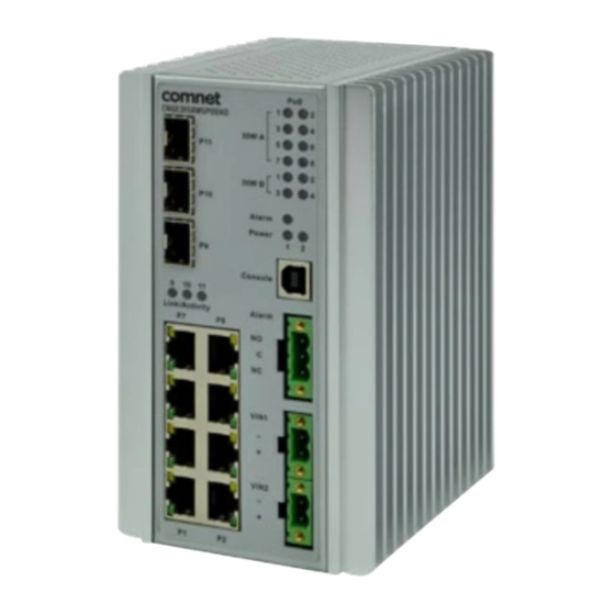
The ComNet CNGE3FE8MS[POE][HO] has three 100/1000Base-FX SFP ports and eight
10/100Base-TX ports. Two of the SFP ports support 2.5 Gbps SFPs for high speed
communication in bandwidth intensive applications. All SFP ports utilize ComNet
SFP modules for fiber and connector type and distance. The IEEE802.3-compliant unit
offers multiple Ethernet redundancy protocols (MSTP/RSTP/STP/ERPS (G.8032)) which
protect your applications from network interruptions or temporary malfunctions by
redirecting transmission within the network. The switch provides advanced IP-based
management that can limit the maximum bandwidth for each connected IP device,
allowing the user to adjust usage. Two models are available which supply Power
over Ethernet (PoE). The CNGE3FE8MSPOE model provides eight electrical ports
supporting up to thirty watts of power. On the CNGE3FE8MSPOEHO model, four
of the eight PoE ports can support up to sixty watts of PoE power. All PoE ports are
IEEE802.3at compliant.
Rev. 11.7.17
Advertisement
Table of Contents

Related Manuals for Comnet CNGE3FE8MSPOE


Summary of Contents for Comnet CNGE3FE8MSPOE
- Page 1 IP device, allowing the user to adjust usage. Two models are available which supply Power over Ethernet (PoE). The CNGE3FE8MSPOE model provides eight electrical ports supporting up to thirty watts of power. On the CNGE3FE8MSPOEHO model, four of the eight PoE ports can support up to sixty watts of PoE power.
-
Page 2: Table Of Contents
INSTRUCTION MANUAL CNGE3FE8MS[POE][HO] Contents Regulatory Compliance Statement Warranty Disclaimer Safety Information Hardware Installation Installing the Switch on DIN-Rail Wall Mounting Installation Hardware Overview Power Supply Front Panel LEDs POEHO 60 W PoE Model WEB Management Login Configuration Green Ethernet Thermal Protection DHCP DHCP Pool Configuration Security... - Page 3 INSTRUCTION MANUAL CNGE3FE8MS[POE][HO] Ethernet Ring Protection Switch Configuration MAC Table VLAN Translation VLANs Private VLANs Protocol-based VLAN Voice VLAN Mirroring & Remote Mirroring Configuration UPnP GVRP Monitor Menu System CUP Load Input Power Status System IP Status System Log Port State Green Ethernet Thermal Protection Ports...
- Page 4 INSTRUCTION MANUAL CNGE3FE8MS[POE][HO] Diagnostics Menu Ping Ping6 PHYtest Maintenance Menu Restart Device Factory Defaults Software Configuration Using Switch CLI About CLI Management CLI Management by RS-232 Serial Console CLI Management by Telnet Commander Groups Quick Start Log In and Reset Configuration to Factory Default Set Device Hostname and Admin User Password Set VLAN 1 IP Address Display and Save Configuration to Flash...
- Page 5 INSTRUCTION MANUAL CNGE3FE8MS[POE][HO] Understanding Privilege Levels Configuring Privilege Level Passwords Understanding Terminal Parameters Changing Terminal Parameters Using Banners Configuring Banners Configuring the System Configuration Example Resetting or Removing Condiguration with “no” Using “no” Forms Managing Users Adding, Modifying, and Deletion Users Using Show Commands Listing All Show Commands Show running-config...
-
Page 6: Regulatory Compliance Statement
ComNet warrants that all ComNet products are free from defects in material and workmanship for a specified warranty period from the invoice date for the life of the installation. ComNet will repair or replace products found by ComNet to be defective within this warranty period, with shipment expenses apportioned by ComNet and the distributor. -
Page 7: Safety Information
INSTRUCTION MANUAL CNGE3FE8MS[POE][HO] Safety Information » Only ComNet service personnel can service the equipment. Please contact ComNet Technical Support. » The equipment should be installed in locations with controlled access, or other means of security, and controlled by persons of authority. When operating at temperatures above 51º C, the equipment surfaces will be hot to the touch. -
Page 8: Hardware Installation
INSTRUCTION MANUAL CNGE3FE8MS[POE][HO] Hardware Installation Installing the Switch on DIN-Rail Each switch has a Din-Rail kit on the rear panel. The DIN-Rail kit affixes the switch to the DIN-Rail. TECH SUPPORT: 1.888.678.9427 INS_CNGE3FE8MS[POE][HO] Rev. 11.7.17 PAGE 8... - Page 9 INSTRUCTION MANUAL CNGE3FE8MS[POE][HO] It is easy to install the switch on the Din-Rail: Mount Series on DIN-Rail Step 1: Tilt the switch and mount the metal spring to DIN-Rail. Step 2: Push the switch toward the DIN-Rail until you hear the spring snap into place TECH SUPPORT: 1.888.678.9427 INS_CNGE3FE8MS[POE][HO] Rev.
-
Page 10: Wall Mounting Installation
INSTRUCTION MANUAL CNGE3FE8MS[POE][HO] Wall Mounting Installation Each switch has another installation method for users to fix the switch. A wall mount panel can be found in the package. The following steps show how to mount the switch on the wall: Mounting the switch on a wall Note: For drywall applications where no studs are available, use drywall anchors rated for 50 lbs or more. -
Page 11: Hardware Overview
INSTRUCTION MANUAL CNGE3FE8MS[POE][HO] Hardware Overview CNGE3FE8MS[POE][HO] Call-out Description 1 × 100/1000Base-FX SFP Port 2 × 100/1000/2500Base-FX SFP Ports Link/Activity LED Indicators for SFP Ports 8 × 10/100Base-TX RJ45 Ports PoE LED Indicators (PoE models only) Alarm and Power LED Indicators USB Console Port Fault Relay 3-Pin Terminal Block Connector Redundant Power 2-Pin Terminal Block Connectors... -
Page 12: Power Supply
For CNGE3FE8MS Models, Power Supply must be 12 to 57 VDC @ 10 W max. For CNGE3FE8MSPOE Model, Power Supply must be 44 to 57 VDC @ 250W max. For CNGE3FE8MSPOEHO Model, Power Supply must be 44 to 57 VDC @ 370W max. -
Page 13: Web Management
INSTRUCTION MANUAL CNGE3FE8MS[POE][HO] WEB Management Login Open a web browser and navigate to the switch using http:// and the IP address of the switch. The default IP address is 192.168.10.1 This is the main login page. Default user name is “admin” with maximum length 32 Default password is “admin”... - Page 14 INSTRUCTION MANUAL CNGE3FE8MS[POE][HO] Menu Trees The following tree views show the available menus within the switch web GUI. It offers the user quick access to all the configuration settings within the switch. Configuration Menu TECH SUPPORT: 1.888.678.9427 INS_CNGE3FE8MS[POE][HO] Rev. 11.7.17 PAGE 14...
- Page 15 INSTRUCTION MANUAL CNGE3FE8MS[POE][HO] Monitor Menu Diagnostics Menu TECH SUPPORT: 1.888.678.9427 INS_CNGE3FE8MS[POE][HO] Rev. 11.7.17 PAGE 15...
- Page 16 INSTRUCTION MANUAL CNGE3FE8MS[POE][HO] Maintenance Menu TECH SUPPORT: 1.888.678.9427 INS_CNGE3FE8MS[POE][HO] Rev. 11.7.17 PAGE 16...
-
Page 17: Configuration
INSTRUCTION MANUAL CNGE3FE8MS[POE][HO] Configuration System Information The switch system information is provided here. Object Description System Contact The textual identification of the contact person for this managed node, together with information on how to contact this person. The allowed string length is 0 to 255, and the allowed content is the ASCII characters from 32 to 126. - Page 18 INSTRUCTION MANUAL CNGE3FE8MS[POE][HO] System IP Configure IP basic settings, control IP interfaces and IP routes. The maximum number of interfaces supported is 8 and the maximum number of routes is 32. Object Description IP Configuration Mode Configure whether the IP stack should act as a Host or a Router. In Host mode, IP traffic between interfaces will not be routed.
- Page 19 INSTRUCTION MANUAL CNGE3FE8MS[POE][HO] Object Description IPv4 Address The IPv4 address of the interface in dotted decimal notation. If DHCP is enabled, this field configures the fallback address. The field may be left blank if IPv4 operation on the interface is not desired - or no DHCP fallback address is desired. IPv4 Mask The IPv4 network mask, in number of bits (prefix length).
- Page 20 INSTRUCTION MANUAL CNGE3FE8MS[POE][HO] System NTP Configure NTP on this page. Object Description Mode Indicates the NTP mode operation. Possible modes are: Enabled: Enable NTP client mode operation. Disabled: Disable NTP client mode operation. Server # Provide the IPv4 or IPv6 address of a NTP server. IPv6 address is in 128-bit records represented as eight fields of up to four hexadecimal digits with a colon separating each field (:).
- Page 21 INSTRUCTION MANUAL CNGE3FE8MS[POE][HO] System Time This page allows you to configure the Time Zone. Object Description Time Zone Configuration Time Zone Lists various Time Zones worldwide. Select appropriate Time Zone from the drop down Acronym User can set the acronym of the time zone. This is a User configurable acronym to identify the time zone. ( Range : Up to 16 characters ) Daylight Saving Time Configuration Daylight...
- Page 22 INSTRUCTION MANUAL CNGE3FE8MS[POE][HO] Object Description End time settings Week Select the ending week number. Select the ending day. Month Select the ending month. Hours Select the ending hour. Minutes Select the ending minute Offset settings Offset Enter the number of minutes to add during Daylight Saving Time. ( Range: 1 to 1440 ) Non Recurring Configurations Start time settings Month...
- Page 23 INSTRUCTION MANUAL CNGE3FE8MS[POE][HO] System Log Configure System Log on this page. Object Description Server Mode Indicates the server mode operation. When the mode operation is enabled, the syslog message will send out to syslog server. The syslog protocol is based on UDP communication and received on UDP port 514 and the syslog server will not send acknowledgments back sender since UDP is a connectionless protocol and it does not provide acknowledgments.
-
Page 24: Green Ethernet
INSTRUCTION MANUAL CNGE3FE8MS[POE][HO] Green Ethernet Object Description LEDs Intensity The LEDs power consumption can be reduced by lowering the LEDs intensity. LEDs intensity could for example be lowered during night time, or they could be turn completely off. It is possible to configure 24 different hours of the day, at where the LEDs intensity should be set. - Page 25 INSTRUCTION MANUAL CNGE3FE8MS[POE][HO] Port Power Savings This page allows the user to configure the port power saving features. Object Description Port Power Savings Configuration Optimize EEE for The switch can be set to optimize EEE for either best power saving or least traffic latency. Port Configuration Port The switch port number of the logical port.
-
Page 26: Thermal Protection
INSTRUCTION MANUAL CNGE3FE8MS[POE][HO] Thermal Protection This page allows the user to inspect and configure the current setting for controlling thermal protection. Thermal protection is used to protect the chip from getting overheated. When the temperature exceeds the configured thermal protection temperature, ports will be turned off in order to decrease the power consumption. - Page 27 INSTRUCTION MANUAL CNGE3FE8MS[POE][HO] Ports This page displays curent port configurations. Ports can also be configured here. Object Description Port This is the logical port number for this row. Description The description of the port. It is an ASCII string no longer than 256 characters. Link The current link state is displayed graphically.
- Page 28 INSTRUCTION MANUAL CNGE3FE8MS[POE][HO] Object Description Frame Check Length Configures whether frames with incorrect frame length in the EtherType/Length field shall be dropped. An Ethernet frame contains a field EtherType which can be used to indicate the frame payload size (in bytes) for values of 1535 and below. If the EtherType/Length field is above 1535, it indicates that the field is used as an EtherType (indicating which protocol is encapsulated in the payload of the frame).
-
Page 29: Dhcp
INSTRUCTION MANUAL CNGE3FE8MS[POE][HO] DHCP DHCP Server Mode This page configures global mode and VLAN mode to enable/disable DHCP server per system and per VLAN. Object Description Global Mode Mode Configure the operation mode per system. Possible modes are: Enabled: Enable DHCP server per system. Disabled: Disable DHCP server per system. - Page 30 INSTRUCTION MANUAL CNGE3FE8MS[POE][HO] Excluded IP This page configures excluded IP addresses. DHCP server will not allocate these excluded IP addresses to DHCP client. IP Range Define the IP range to be excluded IP addresses. The first excluded IP must be smaller than or equal to the second excluded IP.
- Page 31 INSTRUCTION MANUAL CNGE3FE8MS[POE][HO] Pool This page manages DHCP pools. According to the DHCP pool, DHCP server will allocate IP address and deliver configuration parameters to DHCP client. Object Description Pool Setting Add or delete pools. Adding a pool and giving a name is to create a new pool with “default” configuration. If you want to configure all settings including type, IP subnet mask and lease time, you can click the pool name to go into the configuration page.
-
Page 32: Dhcp Pool Configuration
INSTRUCTION MANUAL CNGE3FE8MS[POE][HO] DHCP Pool Configuration DHCP Pool Configuration Help DHCP Pool Configuration This page configures all settings of a DHCP pool. TECH SUPPORT: 1.888.678.9427 INS_CNGE3FE8MS[POE][HO] Rev. 11.7.17 PAGE 32... - Page 33 INSTRUCTION MANUAL CNGE3FE8MS[POE][HO] Object Description Pool Name Select a pool by pool name. Setting Name Display the selected pool name. Type Specify which type of the pool is. Network: the pool defines a pool of IP addresses to service more than one DHCP client. Host: the pool services for a specific DHCP client identified by client identifier or hardware address.
- Page 34 INSTRUCTION MANUAL CNGE3FE8MS[POE][HO] Object Description Vendor i Class DHCP option 60. Identifier Specify to be used by DHCP client to optionally identify the vendor type and configuration of a DHCP client. DHCP server will deliver the corresponding option 43 specific information to the client that sends option 60 vendor class identifier.
-
Page 35: Dhcp Snooping
INSTRUCTION MANUAL CNGE3FE8MS[POE][HO] DHCP Snooping Configure DHCP Snooping on this page. Object Description Snooping Mode Indicates the DHCP snooping mode operation. Possible modes are: Enabled: Enable DHCP snooping mode operation. When DHCP snooping mode operation is enabled, the DHCP requests messages will be forwarded to trusted ports and only allow reply packets from trusted ports. - Page 36 INSTRUCTION MANUAL CNGE3FE8MS[POE][HO] DHCP Relay A DHCP relay agent is used to forward and to transfer DHCP messages between the clients and the server when they are not in the same subnet domain. It stores the incoming interface IP address in the GIADDR field of the DHCP packet. The DHCP server can use the value of GIADDR field to determine the assigned subnet.
-
Page 37: Security
INSTRUCTION MANUAL CNGE3FE8MS[POE][HO] Security Switch Security Users This page provides an overview of the current users. Currently the only way to login as another user on the web server is to close and reopen the browser. Object Description User Name A string identifying the user name that this entry should belong to. -
Page 38: Privilege Levels
INSTRUCTION MANUAL CNGE3FE8MS[POE][HO] Privilege Levels This page provides an overview of the privilege levels. Group Name The name identifying the privilege group. In most cases, a privilege level group consists of a single module (e.g. LACP, RSTP or QoS), but a few of them contains more than one. The following description defines these privilege level groups in details: System: Contact, Name, Location, Timezone, Daylight Saving Time, Log. -
Page 39: Authentication Method
INSTRUCTION MANUAL CNGE3FE8MS[POE][HO] Authentication Method This page allows you to configure how a user is authenticated when he logs into the switch via one of the management client interfaces. Object Description Client The management client for which the configuration below applies. Methods Method can be set to one of the following values: •... - Page 40 INSTRUCTION MANUAL CNGE3FE8MS[POE][HO] Configure SSH on this page. Object Description Mode Indicates the SSH mode operation. Possible modes are: Enabled: Enable SSH mode operation. Disabled: Disable SSH mode operation. Apply Click to apply changes. Reset Click to revert to previous values. TECH SUPPORT: 1.888.678.9427 INS_CNGE3FE8MS[POE][HO] Rev.
- Page 41 INSTRUCTION MANUAL CNGE3FE8MS[POE][HO] HTTPS Configure HTTPS on this page. Object Description Mode Indicates the HTTPS mode operation. When the current connection is HTTPS, to apply HTTPS disabled mode operation will automatically redirect web browser to an HTTP connection. Possible modes are: Enabled: Enable HTTPS mode operation. Disabled: Disable HTTPS mode operation. Automatic Indicates the HTTPS redirect mode operation.
-
Page 42: Access Management
INSTRUCTION MANUAL CNGE3FE8MS[POE][HO] Access Management Configure access management table on this page. The maximum number of entries is 16. If the application’s type matches any one of the access management entries, it will allow access to the switch. Object Description Mode Indicates the access management mode operation. - Page 43 INSTRUCTION MANUAL CNGE3FE8MS[POE][HO] SNMP System Configure SNMP on this page. Object Description Mode Indicates the SNMP mode operation. Possible modes are: Enabled: Enable SNMP mode operation. Disabled: Disable SNMP mode operation. Version Indicates the SNMP supported version. Possible versions are: SNMP v1: Set SNMP supported version 1.
- Page 44 INSTRUCTION MANUAL CNGE3FE8MS[POE][HO] SNMP Trap Configure SNMP trap on this page. Object Description Global Settings Mode Indicates the trap mode operation. Possible modes are: Enabled: Enable SNMP trap mode operation. Disabled: Disable SNMP trap mode operation. Trap Destination Configurations Name Indicates the trap Configuration’s name.
- Page 45 INSTRUCTION MANUAL CNGE3FE8MS[POE][HO] Click on “Add New Entry”. The SNMP Trap Configuration page includes the following fields: Object Description Trap Mode Indicates the SNMP trap mode operation. Possible modes are: Enabled: Enable SNMP trap mode operation. Disabled: Disable SNMP trap mode operation. Trap Version Indicates the SNMP trap supported version.
- Page 46 INSTRUCTION MANUAL CNGE3FE8MS[POE][HO] Object Description Trap Inform Indicates the SNMP trap inform timeout. The allowed range is 0 to 2147. Timeout (seconds) Trap Inform Indicates the SNMP trap informs retry times. The allowed range is 0 to 255. Retry Times Trap Probe Indicates the SNMP trap probe security engine ID mode of operation.
-
Page 47: Snmp Communities
INSTRUCTION MANUAL CNGE3FE8MS[POE][HO] SNMP Communities Configure SNMPv3 community table on this page. The entry index key is Community. Object Description Delete Check to delete the entry. It will be deleted during the next save. Community Indicates the community access string to permit access to SNMPv3 agent. The allowed string length is 1 to 32, and the allowed content is ASCII characters from 33 to 126. - Page 48 INSTRUCTION MANUAL CNGE3FE8MS[POE][HO] SNMP Users Configure SNMPv3 user table on this page. The entry index keys are Engine ID and User Name. Object Description Delete Check to delete the entry. It will be deleted during the next save. Engine ID An octet string identifying the engine ID that this entry should belong to.
- Page 49 INSTRUCTION MANUAL CNGE3FE8MS[POE][HO] SNMP Groups Configure SNMPv3 group table on this page. The entry index keys are Security Model and Security Name. Object Description Delete Check to delete the entry. It will be deleted during the next save. Security Model Indicates the security model that this entry should belong to.
- Page 50 INSTRUCTION MANUAL CNGE3FE8MS[POE][HO] SNMP Views Configure SNMPv3 view table on this page. The entry index keys are View Name and OID Subtree. Object Description Delete Check to delete the entry. It will be deleted during the next save. View Name A string identifying the view name that this entry should belong to.
- Page 51 INSTRUCTION MANUAL CNGE3FE8MS[POE][HO] SNMP Access Configure SNMPv3 access table on this page. The entry index keys are Group Name, Security Model and Security Level. Object Description Delete Check to delete the entry. It will be deleted during the next save. Group Name A string identifying the group name that this entry should belong to.
- Page 52 INSTRUCTION MANUAL CNGE3FE8MS[POE][HO] RMON Statistics Configure RMON Statistics table on this page. The entry index key is ID. Object Description Delete Check to delete the entry. It will be deleted during the next save. Indicates the index of the entry. The range is from 1 to 65535. Data Source Indicates the port ID which wants to be monitored.
- Page 53 INSTRUCTION MANUAL CNGE3FE8MS[POE][HO] Alarm Configure RMON Alarm table on this page. The entry index key is ID. Object Description Delete Check to delete the entry. It will be deleted during the next save. Indicates the index of the entry. The range is from 1 to 65 Interval Indicates the interval in seconds for sampling and comparing the rising and falling threshold.
- Page 54 INSTRUCTION MANUAL CNGE3FE8MS[POE][HO] Event Configure RMON Event table on this page. The entry index key is ID. Object Description Delete Check to delete the entry. It will be deleted during the next save. Indicates the index of the entry. The range is from 1 to 65535. Desc Indicates this event, the string length is from 0 to 127, default is a null string.
-
Page 55: Network
INSTRUCTION MANUAL CNGE3FE8MS[POE][HO] Network Limit Control This page allows you to configure the Port Security Limit Control system and port settings. Limit Control allows for limiting the number of users on a given port. A user is identified by a MAC address and VLAN ID. - Page 56 INSTRUCTION MANUAL CNGE3FE8MS[POE][HO] Object Description System Configuration Mode Indicates if Limit Control is globally enabled or disabled on the switch. If globally disabled, other modules may still use the underlying functionality, but limit checks and corresponding actions are disabled. Aging Enabled If checked, secured MAC addresses are subject to aging as discussed under Aging Period .
- Page 57 INSTRUCTION MANUAL CNGE3FE8MS[POE][HO] Object Description Port Configuration Port The port number to which the configuration below applies. Mode Controls whether Limit Control is enabled on this port. Both this and the Global Mode. must be set to Enabled for Limit Control to be in effect. Notice that other modules may still use the underlying port security features without enabling Limit Control on a given port.
-
Page 58: Screen
INSTRUCTION MANUAL CNGE3FE8MS[POE][HO] Screen This page allows you to configure the IEEE 802.1X and MAC-based authentication system and port settings. The IEEE 802.1X standard defines a port-based access control procedure that prevents unauthorized access to a network by requiring users to first submit credentials for authentication. - Page 59 INSTRUCTION MANUAL CNGE3FE8MS[POE][HO] Object Description System Configuration Mode Indicates if NAS is globally enabled or disabled on the switch. If globally disabled, all ports are allowed forwarding of frames. Reauthentication If checked, successfully authenticated supplicants/clients are reauthenticated after the interval Enabled specified by the Reauthentication Period.
- Page 60 INSTRUCTION MANUAL CNGE3FE8MS[POE][HO] Object Description Aging Period This setting applies to the following modes, i.e. modes using the Port Security functionality to secure MAC addresses: • Single 802.1X • Multi 802.1X • MAC-Based Auth. When the NAS module uses the Port Security module to secure MAC addresses, the Port Security module needs to check for activity on the MAC address in question at regular intervals and free resources if no activity is seen within a given period of time.
- Page 61 INSTRUCTION MANUAL CNGE3FE8MS[POE][HO] Object Description Guest VLAN A Guest VLAN is a special VLAN - typically with limited network access - on which Enabled 802.1X-unaware clients are placed after a network administrator-defined timeout. The switch follows a set of rules for entering and leaving the Guest VLAN as listed below. The “Guest VLAN Enabled”...
- Page 62 INSTRUCTION MANUAL CNGE3FE8MS[POE][HO] Object Description Admin State If NAS is globally enabled, this selection controls the port’s authentication mode. The following modes are available: Force Authorized In this mode, the switch will send one EAPOL Success frame when the port link comes up, and any client on the port will be allowed network access without authentication.
- Page 63 INSTRUCTION MANUAL CNGE3FE8MS[POE][HO] Object Description RADIUS-Assigned When RADIUS-Assigned QoS is both globally enabled and enabled (checked) on a given QoS Enabled port, the switch reacts to QoS Class information carried in the RADIUS Access-Accept packet transmitted by the RADIUS server when a supplicant is successfully authenticated. If present and valid, traffic received on the supplicant’s port will be classified to the given QoS Class.
- Page 64 INSTRUCTION MANUAL CNGE3FE8MS[POE][HO] Object Description Guest VLAN When Guest VLAN is both globally enabled and enabled (checked) for a given port, the switch Enabled considers moving the port into the Guest VLAN according to the rules outlined below. This option is only available for EAPOL-based modes, i.e.: •...
- Page 65 INSTRUCTION MANUAL CNGE3FE8MS[POE][HO] Ports Configure the ACL parameters (ACE) of each switch port. These parameters will affect frames received on a port unless the frame matches a specific ACE. Object Description Port The logical port for the settings contained in the same row. Policy ID Select the policy to apply to this port.
- Page 66 INSTRUCTION MANUAL CNGE3FE8MS[POE][HO] Object Description Shutdown Specify the port shut down operation of this port. The allowed values are: Enabled: If a frame is received on the port, the port will be disabled. Disabled: Port shut down is disabled. The default value is “Disabled”. Note: The shutdown feature only works when the packet length is less than 1518(without VLAN tags).
- Page 67 INSTRUCTION MANUAL CNGE3FE8MS[POE][HO] Rate Limiters Configure the rate limiter for the ACL of the switch. Object Description Rate Limiter ID The rate limiter ID for the settings contained in the same row. Rate The rate range is located 0-3276700 in pps. Or 0, 100, 200, 300, ..., 1000000 in kbps.
- Page 68 INSTRUCTION MANUAL CNGE3FE8MS[POE][HO] Access Control List This page shows the Access Control List (ACL), which is made up of the ACEs defined on this switch. Each row describes the ACE that is defined. The maximum number of ACEs is 256 on each switch. Click on the lowest plus sign to add a new ACE to the list.
- Page 69 INSTRUCTION MANUAL CNGE3FE8MS[POE][HO] Object Description Clear Click to clear the counters. Object Description Ingress Port Select the ingress port for which this ACE applies. All: The ACE applies to all port. Port n: The ACE applies to this port number, where n is the number of the switch port. Policy Filter Specify the policy number filter for this ACE.
- Page 70 INSTRUCTION MANUAL CNGE3FE8MS[POE][HO] Object Description EVC Policer ID Select which EVC policer ID to apply on this ACE. The allowed values are Disabled or the values 1 through 256. Port Redirect Frames that hit the ACE are redirected to the port number specified here. The rate limiter will affect these ports.
- Page 71 INSTRUCTION MANUAL CNGE3FE8MS[POE][HO] Object Description VLAN ID Filter Specify the VLAN ID filter for this ACE. Any: No VLAN ID filter is specified. (VLAN ID filter status is “don’t-care”.) Specific: If you want to filter a specific VLAN ID with this ACE, choose this value. A field for entering a VLAN ID number appears.
- Page 72 INSTRUCTION MANUAL CNGE3FE8MS[POE][HO] Object Description IP/Ethernet Specify whether frames can hit the action according to their ARP/RARP hardware address length Length (HLN) and protocol address length (PLN) settings. 0: ARP/RARP frames where the HLN is not equal to Ethernet (0x06) or the (PLN) is not equal to IPv4 (0x04).
- Page 73 INSTRUCTION MANUAL CNGE3FE8MS[POE][HO] Object Description SIP Address When “Host” or “Network” is selected for the source IP filter, you can enter a specific SIP address in dotted decimal notation. SIP Mask When “Network” is selected for the source IP filter, you can enter a specific SIP mask in dotted decimal notation.
- Page 74 INSTRUCTION MANUAL CNGE3FE8MS[POE][HO] Object Description ICMP Code Specify the ICMP code filter for this ACE. Filter Any: No ICMP code filter is specified (ICMP code filter status is “don’t-care”). Specific: If you want to filter a specific ICMP code filter with this ACE, you can enter a specific ICMP code value. A field for entering an ICMP code value appears.
- Page 75 INSTRUCTION MANUAL CNGE3FE8MS[POE][HO] Object Description TCP URG Specify the TCP “Urgent Pointer field significant” (URG) value for this ACE. 0: TCP frames where the URG field is set must not be able to match this entry. 1: TCP frames where the URG field is set must be able to match this entry.
- Page 76 INSTRUCTION MANUAL CNGE3FE8MS[POE][HO] IP Source Guard Configuration This page provides IP Source Guard related configurations. Object Description Mode of IP Enable the Global IP Source Guard or disable the Global IP Source Guard. All configured ACEs Source Guard will be lost when the mode is enabled. Configuration Port Mode Specify IP Source Guard is enabled on which ports.
- Page 77 INSTRUCTION MANUAL CNGE3FE8MS[POE][HO] Static Table Object Description Delete Check to delete the entry. It will be deleted during the next save. Port The logical port for the settings. VLAN ID The vlan id for the settings. IP Address Allowed Source IP address. MAC address Allowed Source MAC address.
-
Page 78: Arp Inspection
INSTRUCTION MANUAL CNGE3FE8MS[POE][HO] ARP Inspection Port Configuration This page provides ARP Inspection related configuration. Object Description Mode of ARP Enable the Global ARP Inspection or disable the Global ARP Inspection. Inspection Configuration Port Mode Specify ARP Inspection is enabled on which ports. Only when both Global Mode and Port Configuration Mode on a given port are enabled, ARP Inspection is enabled on this given port. - Page 79 INSTRUCTION MANUAL CNGE3FE8MS[POE][HO] VLAN Configuration Each page shows up to 9999 entries from the VLAN table, default being 20, selected through the “entries per page” input field. When first visited, the web page will show the first 20 entries from the beginning of the VLAN Table.
- Page 80 INSTRUCTION MANUAL CNGE3FE8MS[POE][HO] Static Table Object Description Delete Check to delete the entry. It will be deleted during the next save. Port The logical port for the settings VLAN ID The vlan id for the settings. MAC Address Allowed Source MAC address in ARP request packets. IP Address Allowed Source IP address in ARP request packets.
- Page 81 INSTRUCTION MANUAL CNGE3FE8MS[POE][HO] Dynamic Table Entries in the Dynamic ARP Inspection Table are shown on this page. The Dynamic ARP Inspection Table contains up to 256 entries, and is sorted first by port, then by VLAN ID, then by MAC address, and then by IP address.
- Page 82 INSTRUCTION MANUAL CNGE3FE8MS[POE][HO] RADIUS This page allows you to configure the RADIUS servers. Object Description Global Configuration Timeout Timeout is the number of seconds, in the range 1 to 1000, to wait for a reply from a RADIUS server before retransmitting the request. Retransmit Retransmit is the number of times, in the range 1 to 1000, a RADIUS request is retransmitted to a server that is not responding.
- Page 83 INSTRUCTION MANUAL CNGE3FE8MS[POE][HO] Object Description Timeout This optional setting overrides the global timeout value. Leaving it blank will use the global timeout value. Retransmit This optional setting overrides the global retransmit value. Leaving it blank will use the global retransmit value. This optional setting overrides the global key.
- Page 84 INSTRUCTION MANUAL CNGE3FE8MS[POE][HO] TACACS+ This page allows you to configure the TACACS+ servers. Object Description Global Configuration Timeout Timeout is the number of seconds, in the range 1 to 1000, to wait for a reply from a TACACS+ server before it is considered to be dead. Deadtime Deadtime, which can be set to a number between 0 to 1440 minutes, is the period during which the switch will not send new requests to a server that has failed to respond to a...
-
Page 85: Aggregation
INSTRUCTION MANUAL CNGE3FE8MS[POE][HO] Aggregation Static This page is used to configure the Aggregation hash mode and the aggregation group. Object Description Hash Code Contributors Source MAC Address The Source MAC address can be used to calculate the destination port for the frame. Check to enable the use of the Source MAC address, or uncheck to disable. - Page 86 INSTRUCTION MANUAL CNGE3FE8MS[POE][HO] Apply Click to apply changes. Reset Click to revert to previous values. LACP This page allows the user to inspect the current LACP port configurations and possibly change them as well. Object Description Port The switch port number. LACP Enabled Controls whether LACP is enabled on this switch port.
-
Page 87: Loop Protection
INSTRUCTION MANUAL CNGE3FE8MS[POE][HO] Loop Protection Please note that Loop Protection cannot be used in conjunction with ERPS or STP/RSTP/MSTP on the same switch. This page allows the user to inspect the current Loop Protection configurations and possibly change them as well. Object Description General Settings... -
Page 88: Spanning Tree
INSTRUCTION MANUAL CNGE3FE8MS[POE][HO] Reset Click to revert to previous values. Spanning Tree Please note that Spanning Tree cannot be used in conjunction with ERPS or Loop Protection on the same switch. Bridge Settings This page allows you to configure STP system settings. The settings are used by all STP Bridge Instances in the switch. - Page 89 INSTRUCTION MANUAL CNGE3FE8MS[POE][HO] Object Description Advanced Settings Edge Port BPDU Filtering Control whether a port explicitly configured as Edge will transmit and receive BPDUs. Edge Port BPDU Guard Control whether a port explicitly configured as Edge will disable itself upon reception of a BPDU.
-
Page 90: Msti Mapping
INSTRUCTION MANUAL CNGE3FE8MS[POE][HO] MSTI Mapping This page allows the user to inspect the current STP MSTI bridge instance priority configurations and possibly change them as well. Object Description Configuration Identification Configuration The name identifying the VLAN to MSTI mapping. Bridges must share the name and revision Name (see below), as well as the VLAN-to-MSTI mapping configuration in order to share spanning trees for MSTI’s (Intra-region). -
Page 91: Msti Priorities
INSTRUCTION MANUAL CNGE3FE8MS[POE][HO] MSTI Priorities This page allows the user to inspect the current STP MSTI bridge instance priority configurations and possibly change them as well. Object Description MSTI The bridge instance. The CIST is the default instance, which is always active. Priorities Controls the bridge priority. - Page 92 INSTRUCTION MANUAL CNGE3FE8MS[POE][HO] CIST Ports This page allows the user to inspect the current STP CIST port configurations, and possibly change them as well. This page contains settings for physical and aggregated ports. Object Description Port The switch port number of the logical STP port. STP Enabled Controls whether STP is enabled on this switch port.
- Page 93 INSTRUCTION MANUAL CNGE3FE8MS[POE][HO] Object Description Restricted TCN If enabled, causes the port not to propagate received topology change notifications and topology changes to other ports. If set it can cause temporary loss of connectivity after changes in a spanning tree’s active topology as a result of persistently incorrect learned station location information. It is set by a network administrator to prevent bridges external to a core region of the network, causing address flushing in that region, possibly because those bridges are not under the full control of the administrator or the physical link state of the attached LANs transits frequently.
- Page 94 INSTRUCTION MANUAL CNGE3FE8MS[POE][HO] Object Description Port The switch port number of the corresponding STP CIST (and MSTI) port. Path Cost Controls the path cost incurred by the port. The Auto setting will set the path cost as appropriate by the physical link speed, using the 802.1D recommended values.
-
Page 95: Ipmc Profile
INSTRUCTION MANUAL CNGE3FE8MS[POE][HO] IPMC Profile Profile Table This page provides IPMC Profile related configurations. The IPMC profile is used to deploy the access control on IP multicast streams. It is allowed to create at maximum 64 Profiles with at maximum 128 corresponding rules for each. Object Description Global Profile Mode... - Page 96 INSTRUCTION MANUAL CNGE3FE8MS[POE][HO] IPMC Profile Rule Settings This page provides the filtering rule settings for a specific IPMC profile. It displays the configured rule entries in precedence order. First rule entry has highest priority in lookup, while the last rule entry has lowest priority in lookup.
-
Page 97: Address Entry
INSTRUCTION MANUAL CNGE3FE8MS[POE][HO] Address Entry This page provides address range settings used in IPMC profile. The address entry is used to specify the address range that will be associated with IPMC Profile. It is allowed to create at maximum 128 address entries in the system. Object Description Delete... -
Page 98: Mvr
INSTRUCTION MANUAL CNGE3FE8MS[POE][HO] This page provides MVR related configurations. The MVR feature enables multicast traffic forwarding on the Multicast VLANs. In a multicast television application, a PC or a network television or a set-top box can receive the multicast stream. Multiple set-top boxes or PCs can be connected to one subscriber port, which is a switch port configured as an MVR receiver port. - Page 99 INSTRUCTION MANUAL CNGE3FE8MS[POE][HO] Object Description IGMP Address Define the IPv4 address as source address used in IP header for IGMP control frames. The default IGMP address is not set (0.0.0.0). When the IGMP address is not set, system uses IPv4 management address of the IP interface associated with this VLAN.
-
Page 100: Ipmc
INSTRUCTION MANUAL CNGE3FE8MS[POE][HO] IPMC IGMP Snooping Basic Configuration This page provides IGMP Snooping related configuration. Object Description Snooping Enabled Enable the Global IGMP Snooping. Unregistered IPMCv4 Enable unregistered IPMCv4 traffic flooding. Flooding Enabled The flooding control takes effect only when IGMP Snooping is enabled. When IGMP Snooping is disabled, unregistered IPMCv4 traffic flooding is always active in spite of this setting. - Page 101 INSTRUCTION MANUAL CNGE3FE8MS[POE][HO] VLAN Configuration Each page shows up to 99 entries from the VLAN table, default being 20, selected through the “entries per page” input field. When first visited, the web page will show the first 20 entries from the beginning of the VLAN Table.
- Page 102 INSTRUCTION MANUAL CNGE3FE8MS[POE][HO] Object Description LLQI(LMQI for Last Member Query Interval. IGMP) The Last Member Query Time is the time value represented by the Last Member Query Interval, multiplied by the Last Member Query Count. The allowed range is 0 to 31744 in tenths of seconds, default last member query interval is 10 in tenths of seconds (1 second).
- Page 103 INSTRUCTION MANUAL CNGE3FE8MS[POE][HO] Port Filtering Profile Object Description Port The logical port for the settings. Filtering Profile Select the IPMC Profile as the filtering condition for the specific port. Summary about the designated profile will be shown by clicking the view button. Profile Management You can inspect the rules of the designated profile by using the following button Button...
- Page 104 INSTRUCTION MANUAL CNGE3FE8MS[POE][HO] MLD Snooping Basic Configuration This page provides MLD Snooping related configuration. Object Description Snooping Enable Enable the Global MLD Snooping. Unregistered IPMCv6 Enable unregistered IPMCv6 traffic flooding. Flooding Enable The flooding control takes effect only when MLD Snooping is enabled. When MLD Snooping is disabled, unregistered IPMCv6 traffic flooding is always active in spite of this setting.
- Page 105 INSTRUCTION MANUAL CNGE3FE8MS[POE][HO] TECH SUPPORT: 1.888.678.9427 INS_CNGE3FE8MS[POE][HO] Rev. 11.7.17 PAGE 105...
- Page 106 INSTRUCTION MANUAL CNGE3FE8MS[POE][HO] VLAN Configuration Each page shows up to 99 entries from the VLAN table, default being 20, selected through the “entries per page” input field. When first visited, the web page will show the first 20 entries from the beginning of the VLAN Table.
- Page 107 INSTRUCTION MANUAL CNGE3FE8MS[POE][HO] Object Description Unsolicited Report Interval. The Unsolicited Report Interval is the time between repetitions of a node’s initial report of interest in a multicast address. The allowed range is 0 to 31744 seconds, default unsolicited report interval is 1 second. Add New MLD VLAN Click to add A new MLD VLAN.
-
Page 108: Lldp
INSTRUCTION MANUAL CNGE3FE8MS[POE][HO] LLDP LLDP This page allows the user to inspect and configure the current LLDP port setting. Object Description LLDP Parameters Tx Interval The switch periodically transmits LLDP frames to its neighbors for having the network discovery information up-to-date. The interval between each LLDP frame is determined by the Tx Interval value. - Page 109 INSTRUCTION MANUAL CNGE3FE8MS[POE][HO] Object Description Mode Select LLDP mode. Rx only The switch will not send out LLDP information, but LLDP information from neighbor units is analyzed. Tx only The switch will drop LLDP information received from neighbors, but will send out LLDP information.
-
Page 110: Poe
INSTRUCTION MANUAL CNGE3FE8MS[POE][HO] This page allows the user to inspect and configure the current PoE port settings. Object Description Reserved Power determined by Allocated mode In this mode the user allocates the amount of power that each port may reserve. The allocated/ reserved power for each port/PD is specified in the Maximum Power fields. - Page 111 INSTRUCTION MANUAL CNGE3FE8MS[POE][HO] Object Description Power Source For being able to determine the amount of power the PD may use, it must be defined what amount of power a power source can deliver. Valid values are in the range 0 to 360 Watts (depending on model). Port Configuration Port This is the logical port number for this row.
-
Page 112: Eps
INSTRUCTION MANUAL CNGE3FE8MS[POE][HO] The Ethernet (Linear) Protection Switch instances are configured here. Object Description Delete This box is used to mark an EPS for deletion in next Save operation. EPS ID The ID of the EPS. Click on the ID of an EPS to enter the configuration page. Domain Port: This will create a EPS in the Port Domain. -
Page 113: Ethernet Protection Switch Configuration
INSTRUCTION MANUAL CNGE3FE8MS[POE][HO] Ethernet Protection Switch Configuration This page allows the user to inspect and configure the current EPS Instance. Object Description Instance Data EPS ID The ID of the EPS. Click on the ID of an EPS to enter the configuration page. Domain Port: This will create a EPS in the Port Domain. - Page 114 INSTRUCTION MANUAL CNGE3FE8MS[POE][HO] Object Description Command None: There is no active local command on this instance. Clear: The active local command will be cleared. Lock Out: This EPS is locked to working (not active). In case of 1:N (more than one EPS with same protecting flow) - when one EPS switch to protecting flow, other EPS is enforced this command Forced Switch: Forced switch to protecting.
- Page 115 INSTRUCTION MANUAL CNGE3FE8MS[POE][HO] The Maintenance Entity Point instances are configured here. Object Description Delete This box is used to mark a MEP for deletion in next Save operation. Instance The ID of the MEP. Click on the ID of a MEP to enter the configuration page. The range is from 1 through 100.
- Page 116 INSTRUCTION MANUAL CNGE3FE8MS[POE][HO] Maintenance Entity End Point Configuration This page allows the user to inspect and configure the current MEP Instance. Object Description Instance Data MEP Instance The ID of the MEP. Domain Port: This is a MEP in the Port Domain. EVC: This is a MEP in the EVC Domain.
- Page 117 INSTRUCTION MANUAL CNGE3FE8MS[POE][HO] Object Description Tagged VID Port MEP: An outer C/S-tag (depending on VLAN Port Type) is added with this VID. Entering '0' means no TAG added. EVC MEP: This is not used. VLAN MEP: This is not used. EVC MIP: On Serval, this is the Subscriber VID that identify the subscriber flow in this EVC where the MIP is active.
- Page 118 INSTRUCTION MANUAL CNGE3FE8MS[POE][HO] Object Description Unicast Peer MAC This MAC will be used when unicast is selected with this peer MEP. Also this MAC is used to create HW checking of receiving CCM PDU (LOC detection) from this MEP. cLOC Fault Cause indicating that no CCM has been received (in 3,5 periods) - from this peer MEP.
- Page 119 INSTRUCTION MANUAL CNGE3FE8MS[POE][HO] Object Description Organization The transmitted second value in the OS TLV OUI field. Specific - OUI Second Organization The transmitted third value in the OS TLV OUI field. Specific - OUI Third Organization The transmitted value in the OS TLV Sub-Type field. Specific - Sub-Type Organization The transmitted value in the OS TLV Value field.
- Page 120 INSTRUCTION MANUAL CNGE3FE8MS[POE][HO] MEP Fault Management Configuration This page allows the user to inspect and configure the Fault Management of the current MEP Instance. Note that the sub-tables of Link Trace, Link Trace State, Client, AIS and LOCK are not supported while the MEP entry is in MPLS(Link/Tunnel/PW/LSP) domain.
- Page 121 INSTRUCTION MANUAL CNGE3FE8MS[POE][HO] Object Description Loop Back Enable Loop Back based on transmitting/receiving LBM/LBR PDU can be enabled/disabled. Loop Back is automatically disabled when all 'To Send' LBM PDU has been transmitted - waiting 5 sec. for all LBR from the end. The DEI to be inserted as PCP bits in TAG (if any).
- Page 122 INSTRUCTION MANUAL CNGE3FE8MS[POE][HO] Object Description Peer MEP This is only used if the 'Unicast MAC' is configured to all zero. The Link Trace Target MAC will be taken from the 'Unicast Peer MAC' configuration of this peer. Unicast MAC This is only used if NOT configured to all zero. This will be used as the Link Trace Target MAC. This is the only way to configure a MIP as Target MAC.
- Page 123 INSTRUCTION MANUAL CNGE3FE8MS[POE][HO] Object Description Size The TST frame size. This is entered as the wanted size (in bytes) of a un-tagged frame containing TST OAM PDU - including CRC (four bytes). Example when 'Size' = 64=> Un-tagged frame size = DMAC(6) + SMAC(6) + TYPE(2) + TST PDU LENGTH(46) + CRC(4) = 64 bytes The transmitted frame will be four bytes longer for each tag added - 8 bytes in case of a tunnel EVC.
- Page 124 INSTRUCTION MANUAL CNGE3FE8MS[POE][HO] Object Description Frame Rate Selecting the frame rate of AIS PDU. This is the inverse of transmission period as described in Y.1731. Protection Selecting this means that the first 3 AIS PDU is transmitted as fast as possible - in case of using this for protection in the end point.
- Page 125 INSTRUCTION MANUAL CNGE3FE8MS[POE][HO] MEP Performance Monitor Configuration This page allows the user to inspect and configure the performance monitor of the current MEP Instance. Performance Monitoring Data Set Enable When enabled this MEP instance will contribute to the 'PM Data Set' gathered by the PM Session.
- Page 126 INSTRUCTION MANUAL CNGE3FE8MS[POE][HO] FLR Interval This is the interval in seconds where the Frame Loss Ratio is calculated. Flow Counting Traffic (service frames) are counted per flow - all priority in one. Oam Counting Loss Measurement can count OAM frames in different ways. Y1713: Loss Measurement is counting OAM frames as service frames as described in Y1731.
- Page 127 INSTRUCTION MANUAL CNGE3FE8MS[POE][HO] Rx Error The accumulated receive error count - since last 'clear'. This is counting if the frame delay is larger than 1 second or if far end residence time is larger than the round trip time. Av Delay Tot The average total delay - since last 'clear'.
- Page 128 INSTRUCTION MANUAL CNGE3FE8MS[POE][HO] Delay Measurement Bins for IFDV A Measurement Bin is a counter that stores the number of delay measurements falling within a specified range, during a Measurement Interval. If the measurement threshold is 5000 us and the total number of Measurement Bins is four, we can give an example as follows.
-
Page 129: This Document
INSTRUCTION MANUAL CNGE3FE8MS[POE][HO] ERPS The ERPS instances are configured here. Please note that ERPS cannot be used in conjunction with Spanning Tree or Loop Protection on the same switch Note: For an example of how to configure an ERPS ring please refer to appendix A at the rear of this document. -
Page 130: Ethernet Ring Protection Switch Configuration
INSTRUCTION MANUAL CNGE3FE8MS[POE][HO] Ethernet Ring Protection Switch Configuration Object Description Instance Data ERPS ID The ID of the Protection group. Port 0 This will create a Port 0 of the switch in the ring. Port 1 This will create “Port 1” of the switch in the Ring. As interconnected sub-ring will have only one ring port, “Port 1”... - Page 131 INSTRUCTION MANUAL CNGE3FE8MS[POE][HO] Object Description Hold Off Time The timing value to be used to make persistent check on Signal Fail before switching. The range of the hold off timer is 0 to 10 seconds in steps of 100 ms Version ERPS Protocol Version - v1 or v2 Revertive...
-
Page 132: Vlan Membership Configuration
INSTRUCTION MANUAL CNGE3FE8MS[POE][HO] Object Description FOP Alarm Failure of Protocol Defect(FOP) status. If FOP is detected, red LED glows; else green LED glows. Apply Click to apply changes. Auto-refresh Check this box to refresh the page automatically. Automatic refresh occurs every 3 seconds. Refresh Click to refresh the page immediately. -
Page 133: Mac Table
INSTRUCTION MANUAL CNGE3FE8MS[POE][HO] MAC Table The MAC Address Table is configured on this page. Set timeouts for entries in the dynamic MAC Table and configure the static MAC table here. Object Description Aging Configuration Disable Automatic Disable the automatic aging of dynamic entries by ticking the item. Aging Aging Time Enter a value in seconds. -
Page 134: Vlan Translation
INSTRUCTION MANUAL CNGE3FE8MS[POE][HO] VLAN Translation Port to Group Configuration This page allows you to configure switch Ports to use a given VLAN Translation Mapping Group. This will enable all VLAN Translation mappings of that group (if any) on the selected switch port. The settings relate to the currently selected stack unit, as reflected by the page header. - Page 135 INSTRUCTION MANUAL CNGE3FE8MS[POE][HO] VLAN Translation Mappings This page displays current VLAN Translation mapping configurations. The settings can also be configured here. Object Description Group ID The VLAN Translation mappings are organized into Groups, identified by the Group ID. This way a port is configured to use a number of VLAN Translation mappings easily by simply configuring it to use a given group.
-
Page 136: Vlans
INSTRUCTION MANUAL CNGE3FE8MS[POE][HO] VLANs This page allows for controlling VLAN configuration on the switch. The page is divided into a global section and a per-port configuration section. Object Description Global VLAN Configuration Allowed Access This field shows the allowed Access VLANs, i.e. it only affects ports configured as Access ports. VLANs Ports in other modes are members of all VLANs specified in the Allowed VLANs field. - Page 137 INSTRUCTION MANUAL CNGE3FE8MS[POE][HO] Object Description Mode The port mode (default is Access) determines the fundamental behavior of the port in question. A port can be in one of three modes as described below. Whenever a particular mode is selected, the remaining fields in that row will be either grayed out or made changeable depending on the mode in question.
- Page 138 INSTRUCTION MANUAL CNGE3FE8MS[POE][HO] Object Description Ingress Filtering Hybrid ports allow for changing ingress filtering. Access and Trunk ports always have ingress filtering enabled. If ingress filtering is enabled (checkbox is checked), frames classified to a VLAN that the port is not a member of get discarded.
-
Page 139: Private Vlans
INSTRUCTION MANUAL CNGE3FE8MS[POE][HO] Private VLANs Membership The Private VLAN membership configurations for the switch can be monitored and modified here. Private VLANs can be added or deleted here. Port members of each Private VLAN can be added or removed here. Private VLANs are based on the source port mask, and there are no connections to VLANs. - Page 140 INSTRUCTION MANUAL CNGE3FE8MS[POE][HO] Port Isolation This page is used for enabling or disabling port isolation on ports in a Private VLAN. A port member of a VLAN can be isolated to other isolated ports on the same VLAN and Private VLAN.
-
Page 141: Vcl
INSTRUCTION MANUAL CNGE3FE8MS[POE][HO] MAC-based VLAN The MAC address to VLAN ID mappings can be configured here. This page allows adding and deleting MAC-based VLAN Classification List entries and assigning the entries to different ports. Object Description Delete To delete a MAC to VLAN ID mapping entry, check this box and press save. The entry will be deleted in the stack. -
Page 142: Protocol-Based Vlan
INSTRUCTION MANUAL CNGE3FE8MS[POE][HO] Protocol-based VLAN Protocol to Group This page allows you to add new Protocol to Group Name (each protocol can be part of only one Group) mapping entries as well as allow you to see and delete already mapped entries for the switch. The displayed settings are: Object Description... - Page 143 INSTRUCTION MANUAL CNGE3FE8MS[POE][HO] Object Description Adding a Click “Add New Entry” to add a new entry in the mapping table. An empty row is added to the table, New Group where Frame Type, Value and the Group Name can be configured as needed. to VLAN The “Delete”...
- Page 144 INSTRUCTION MANUAL CNGE3FE8MS[POE][HO] Group to VLAN This page allows you to map a Group Name (already configured or to be configured in the future) to a VLAN for the switch . The displayed settings are: Object Description Delete To delete a Group Name to VLAN mapping, check this box. The entry will be deleted from the switch during the next Save.
- Page 145 INSTRUCTION MANUAL CNGE3FE8MS[POE][HO] IP Subnet-based VLAN The IP subnet to VLAN ID mappings can be configured here. This page allows adding, updating and deleting IP subnet to VLAN ID mapping entries and assigning them to different ports. Object Description Delete To delete a mapping, check this box and press save.
-
Page 146: Voice Vlan
INSTRUCTION MANUAL CNGE3FE8MS[POE][HO] Voice VLAN Configuration The Voice VLAN feature enables voice traffic forwarding on the Voice VLAN, then the switch can classify and schedule network traffic. It is recommended that there be two VLANs on a port - one for voice, one for data. Before connecting the IP device to the switch, the IP phone should configure the voice VLAN ID correctly. - Page 147 INSTRUCTION MANUAL CNGE3FE8MS[POE][HO] Object Description Port Mode Indicates the Voice VLAN port mode. Possible port modes are: Disabled: Disjoin from Voice VLAN. Auto: Enable auto detect mode. It detects whether there is VoIP phone attached to the specific port and configures the Voice VLAN members automatically. Forced: Force join to Voice VLAN.
- Page 148 INSTRUCTION MANUAL CNGE3FE8MS[POE][HO] Configure VOICE VLAN OUI table on this page. The maximum number of entries is 16. Modifying the OUI table will restart auto detection of OUI process. Object Description Delete Check to delete the entry. It will be deleted during the next save. Telephony OUI A telephony OUI address is a globally unique identifier assigned to a vendor by IEEE.
-
Page 149: Port Classification
INSTRUCTION MANUAL CNGE3FE8MS[POE][HO] Port Classification This page allows you to configure the basic QoS Ingress Classification settings for all switch ports. Object Description Port The port number for which the configuration below applies. Controls the default class of service. All frames are classified to a CoS. There is a one to one mapping between CoS, queue and priority. A CoS of 0 (zero) has the lowest priority. - Page 150 INSTRUCTION MANUAL CNGE3FE8MS[POE][HO] Object Description Tag Class. Shows the classification mode for tagged frames on this port. Disabled: Use default CoS and DPL for tagged frames. Enabled: Use mapped versions of PCP and DEI for tagged frames. Click on the mode in order to configure the mode and/or mapping. Note: This setting has no effect if the port is VLAN unaware.
- Page 151 INSTRUCTION MANUAL CNGE3FE8MS[POE][HO] QoS Ingress Port Classification Configuration The classification mode for tagged frames are configured on this page. Object Description Tag Classification Controls the classification mode for tagged frames on this port. Disabled: Use default QoS class and Drop Precedence Level for tagged frames. Enabled: Use mapped versions of PCP and DEI for tagged frames.
-
Page 152: Port Policing
INSTRUCTION MANUAL CNGE3FE8MS[POE][HO] Port Policing This page allows you to configure the Policer settings for all switch ports. Object Description Port The port number for which the configuration below applies. Enabled Controls whether the policer is enabled on this switch port. Rate Controls the rate for the policer. - Page 153 INSTRUCTION MANUAL CNGE3FE8MS[POE][HO] QoS Ingress Queue Policer Configuration This page allows you to configure the Queue Policer settings for all switch ports. The settings relate to the currently selected stack unit, as reflected by the page header. Object Description Port The port number for which the configuration below applies.
-
Page 154: Port Scheduler
INSTRUCTION MANUAL CNGE3FE8MS[POE][HO] Port Scheduler This page provides an overview of QoS Egress Port Schedulers for all switch ports. Object Description Port The logical port for the settings contained in the same row. Click on the port number in order to configure the schedulers. - Page 155 INSTRUCTION MANUAL CNGE3FE8MS[POE][HO] QoS Egress Port Scheduler and Shapers Configuration This page allows you to configure the Scheduler and Shapers for a specific port. The settings relate to the currently selected stack unit, as reflected by the page header. Object Description Scheduler Mode Controls how many of the queues are scheduled as strict and how many are scheduled as...
- Page 156 INSTRUCTION MANUAL CNGE3FE8MS[POE][HO] Object Description Port Shaper Rate Controls the rate for the port shaper. This value is restricted to 100-3281943 when "Unit" is kbps, and 1-3281 when "Unit" is Mbps. Only shown for Non-service configuration. The rate is internally rounded up to the nearest value supported by the port shaper. Port Shaper Unit Controls the unit of measure for the port shaper rate as kbps or Mbps.
-
Page 157: Port Shaping
INSTRUCTION MANUAL CNGE3FE8MS[POE][HO] Port shaping This page provides an overview of QoS Egress Port Shapers for all switch ports. Object Description Port The logical port for the settings contained in the same row. Click on the port number in order to configure the shapers. - Page 158 INSTRUCTION MANUAL CNGE3FE8MS[POE][HO] QoS Egress Port Tag Remarking Configuration The QoS Egress Port Tag Remarking for a specific port are configured on this page. Object Description Mode Controls the tag remarking mode for this port. Classified: Use classified PCP/DEI values. Default: Use default PCP/DEI values.
- Page 159 INSTRUCTION MANUAL CNGE3FE8MS[POE][HO] Port DSCP This page allows you to configure the basic QoS Port DSCP Configuration settings for all switch ports. Object Description Port The Port column shows the list of ports for which you can configure dscp ingress and egress settings.
- Page 160 INSTRUCTION MANUAL CNGE3FE8MS[POE][HO] DSCP-Based QoS This page allows you to configure the basic QoS DSCP based QoS Ingress Classification settings for all switches. Object Description DSCP Maximum number of supported DSCP values is 64. Trust Controls whether a specific DSCP value is trusted. Only frames with trusted DSCP values are mapped to a specific QoS class and Drop Precedence Level.
- Page 161 INSTRUCTION MANUAL CNGE3FE8MS[POE][HO] DSCP Translation This page allows you to configure the basic QoS DSCP Translation settings for all switches. DSCP translation can be done in Ingress or Egress. Object Description DSCP Maximum number of supported DSCP values are 64 and valid DSCP value ranges from 0 to 63. Ingress Ingress side DSCP can be first translated to new DSCP before using the DSCP for QoS class and DPL map.
-
Page 162: Dscp Classification
INSTRUCTION MANUAL CNGE3FE8MS[POE][HO] DSCP Classification This page allows you to configure the mapping of QoS class and Drop Precedence Level to DSCP value. Object Description QoS Class Actual QoS class. DSCP DP0 Select the classified DSCP value (0-63) for Drop Precedence Level 0. DSCP DP1 Select the classified DSCP value (0-63) for Drop Precedence Level 1. - Page 163 INSTRUCTION MANUAL CNGE3FE8MS[POE][HO] QoS Control List This page shows the QoS Control List(QCL), which is made up of the QCEs. Each row describes a QCE that is defined. The maximum number of QCEs is 256 on each switch. Click on the lowest plus sign to add a new QCE to the list. Object Description Indicates the QCE id.
- Page 164 INSTRUCTION MANUAL CNGE3FE8MS[POE][HO] TECH SUPPORT: 1.888.678.9427 INS_CNGE3FE8MS[POE][HO] Rev. 11.7.17 PAGE 164...
- Page 165 INSTRUCTION MANUAL CNGE3FE8MS[POE][HO] The QCE page includes the following fields: Object Description Port Members Check the checkbox button to include the port in the QCL entry. By default all ports are included. Key Paramente Key configuration is described as below: DMAC Destination MAC address: Possible values are ‘Unicast’, ‘Multicast’, ‘Broadcast’...
- Page 166 INSTRUCTION MANUAL CNGE3FE8MS[POE][HO] Storm Policing Storm control for the switch is configured on this page. There is a unicast storm rate control, multicast storm rate control, and a broadcast storm rate control. These only affect flooded frames, i.e. frames with a (VLAN ID, DMAC) pair not present on the MAC Address table.
-
Page 167: Mirroring & Remote Mirroring Configuration
INSTRUCTION MANUAL CNGE3FE8MS[POE][HO] Mirroring & Remote Mirroring Configuration Mirroring is a feature for switched port analyzer. The administrator can use the Mirroring to debug network problems. The selected traffic can be mirrored or copied on a destination port where a network analyzer can be attached to analyze the network traffic. - Page 168 INSTRUCTION MANUAL CNGE3FE8MS[POE][HO] Object Description Destination The switch is an end node for monitor flow. The destination port(s) and intermediate port(s) are located on this switch. VLAN ID The VLAN ID points out where the monitor packet will copy to. The default VLAN ID is 200. Reflector Port The reflector port is a method to redirect the traffic to Remote Mirroring VLAN.
- Page 169 INSTRUCTION MANUAL CNGE3FE8MS[POE][HO] Object Description Configuration When the switch is running on Remote Mirroring mode, the administrator also needs to check Guideline for whether or not other features are enabled or disabled. All Features For example, the administrator is not disabled the MSTP on reflector port. All monitor traffic will be blocked on reflector port.
-
Page 170: Upnp
INSTRUCTION MANUAL CNGE3FE8MS[POE][HO] UPnP Configure UPnP on this page. Object Description Mode Indicates the UPnP operation mode. Possible modes are: Enabled: Enable UPnP mode operation. Disabled: Disable UPnP mode operation. When the mode is enabled, two ACEs are added automatically to trap UPNP related packets to CPU. The ACEs are automatically removed when the mode is disabled. -
Page 171: Gvrp
INSTRUCTION MANUAL CNGE3FE8MS[POE][HO] GVRP Global Configuration This page allows you to configure the basic GVRP Configuration settings for all switch ports. Object Description GVRP Protocol Join-time is a value in the range 1-20 in the units of centi seconds, i.e. in units of one hundredth of a timers second. -
Page 172: Port Configuration
INSTRUCTION MANUAL CNGE3FE8MS[POE][HO] Port Configuration This page allows you to enable/disable a port for GVRP. Object Description Port The logical port that is to be configured. Mode Mode can be either ‘Disabled’ or ‘GVRP enabled’. These values turn the GVRP feature off or on respectively for the port in question. -
Page 173: Monitor Menu
INSTRUCTION MANUAL CNGE3FE8MS[POE][HO] Monitor Menu System System Information The switch system information is provided here Object Description Contact The system contact configured in Configuration | System | Information | System Contact. Name The system name configured in Configuration | System | Information | System Name. Location The system location configured in Configuration | System | Information | System Location. -
Page 174: Cup Load
INSTRUCTION MANUAL CNGE3FE8MS[POE][HO] CUP Load This page displays the CPU load, using line chart. The load is measured as averaged over the last 100ms, 1 s and 10 seconds intervals. The last 1~256 samples (maximum 256) are graphed, and the last numbers are displayed as text as well. Auto_refresh Check to refresh the page automatically every 3 seconds. -
Page 175: Input Power Status
INSTRUCTION MANUAL CNGE3FE8MS[POE][HO] Input Power Status This page shows the status of the 2 power inputs along with power LED's and the fault relay status. Auto_refresh Check to refresh the page automatically every 3 seconds. Refresh Click to refresh the displayed table starting from the input fields. TECH SUPPORT: 1.888.678.9427 INS_CNGE3FE8MS[POE][HO] Rev. -
Page 176: System Ip Status
INSTRUCTION MANUAL CNGE3FE8MS[POE][HO] System IP Status This page displays the status of the IP protocol layer. The status is defined by the IP interfaces, the IP routes and the neighbour cache (ARP cache) status. Object Description IP Interfaces Interface The name of the interface. Type The address type of the entry. - Page 177 INSTRUCTION MANUAL CNGE3FE8MS[POE][HO] TECH SUPPORT: 1.888.678.9427 INS_CNGE3FE8MS[POE][HO] Rev. 11.7.17 PAGE 177...
-
Page 178: System Log
INSTRUCTION MANUAL CNGE3FE8MS[POE][HO] System Log Each page shows up to 999 table entries, selected through the “entries per page” input field. When first visited, the web page will show the beginning entries of this table. The “Level” input field is used to filter the display system log entries. The “Clear Level”... - Page 179 INSTRUCTION MANUAL CNGE3FE8MS[POE][HO] >>| Click to update the table entries, ending at the last available entry. TECH SUPPORT: 1.888.678.9427 INS_CNGE3FE8MS[POE][HO] Rev. 11.7.17 PAGE 179...
- Page 180 INSTRUCTION MANUAL CNGE3FE8MS[POE][HO] System Detailed Log The switch system detailed log information is provided here. Object Description The ID (>= 1) of the system log entry. Message The detailed message of the system log entry. Refresh Click to update the system log entry to the current entry ID.. |<<...
-
Page 181: Port State
INSTRUCTION MANUAL CNGE3FE8MS[POE][HO] Port State This page provides an overview of the current switch port states. The port states are illustrated as follows: RJ45 ports SFP ports State Disabled Down Link Object Description Auto-refresh Check this box to refresh the page automatically. Automatic refresh occurs every 3 seconds. Refresh Click to refresh the page. -
Page 182: Green Ethernet
INSTRUCTION MANUAL CNGE3FE8MS[POE][HO] Green Ethernet Port Power Savings This page provides the current status for EEE. Object Description Port This is the logical port number for this row. Link Shows if the link is up for the port (green = link up, red = link down). Shows if EEE is enabled for the port (reflects the settings at the Port Power Savings configuration page). -
Page 183: Thermal Protection
INSTRUCTION MANUAL CNGE3FE8MS[POE][HO] Thermal Protection This page shows thermal status of the switch. The thermal settings are configured in Configuration ¦ Thermal Protection Auto_refresh Check to refresh the page automatically every 3 seconds. Refresh Click to refresh screen without Auto_refresh. Ports Traffic Overview This page provides an overview of general traffic statistics for all switch ports. -
Page 184: Qos Statistics
INSTRUCTION MANUAL CNGE3FE8MS[POE][HO] QoS Statistics This page provides statistics for the different queues for all switch ports. Object Description Port The logical port for the settings contained in the same row. There are 8 QoS queues per port. Q0 is the lowest priority queue. Rx/Tx The number of received and transmitted packets per queue Auto_refresh... - Page 185 INSTRUCTION MANUAL CNGE3FE8MS[POE][HO] QCL Status This page shows the QCL status by different QCL users. Each row describes the QCE that is defined. It is a conflict if a specific QCE is not applied to the hardware due to hardware limitations. The maximum number of QCEs is 256 on each switch.
- Page 186 INSTRUCTION MANUAL CNGE3FE8MS[POE][HO] Detailed Statistics This page provides detailed traffic statistics for a specific switch port. Use the port select box to select which switch port details to display. The displayed counters are the totals for receive and transmit, the size counters for receive and transmit, and the error counters for receive and transmit.
- Page 187 INSTRUCTION MANUAL CNGE3FE8MS[POE][HO] Object Description Rx Drops The number of frames dropped due to lack of receive buffers or egress congestion. Rx CRC/Alignment The number of frames received with CRC or alignment errors. Rx Undersize The number of short 1 frames received with valid CRC. Rx Oversize The number of long 2 frames received with valid CRC.
-
Page 188: Dhcp
INSTRUCTION MANUAL CNGE3FE8MS[POE][HO] DHCP DHCP Server Statistics This page displays the database counters and the number of DHCP messages sent and received by DHCP server. Object Description Pool Number of pools. Excluded IP Address Number of excluded IP address ranges. Declined IP Address Number of declined IP addresses. - Page 189 INSTRUCTION MANUAL CNGE3FE8MS[POE][HO] Object Description Offer Number of DHCP OFFER messages sent. Number of DHCP ACK messages sent. Number of DHCP NAK messages sent. Auto_refresh Check to refresh the page automatically every 3 seconds. Clear Click to clear DHCP Message Received and Sent counters. Refresh Click to refresh the page.
- Page 190 INSTRUCTION MANUAL CNGE3FE8MS[POE][HO] Declined IP This page displays declined IP addresses. Declined IP: List of IP addresses declined. Auto_refresh Check to refresh the page automatically every 3 seconds. Refresh Click to refresh the page immediately. TECH SUPPORT: 1.888.678.9427 INS_CNGE3FE8MS[POE][HO] Rev. 11.7.17 PAGE 190...
- Page 191 INSTRUCTION MANUAL CNGE3FE8MS[POE][HO] Snooping Table Each page shows up to 99 entries from the Dynamic DHCP snooping table, default being 20, selected through the “entries per page” input field. When first visited, the web page will show the first 20 entries from the beginning of the Dynamic DHCP snooping Table. The “MAC address”...
- Page 192 INSTRUCTION MANUAL CNGE3FE8MS[POE][HO] Relay Statistics This page provides statistics for DHCP relay. Object Description Server Statistics Transmit to Server The number of packets that are relayed from client to server. Transmit Error The number of packets that resulted in errors while being sent to clients. Receive from Server The number of packets received from server.
- Page 193 INSTRUCTION MANUAL CNGE3FE8MS[POE][HO] Detailed Statistics This page provides statistics for DHCP snooping. Notice that the normal forward per-port TX statistics isn’t increased if the incoming DHCP packet is done by L3 forwarding mechanism. And clear the statistics on specific port may not take effect on global statistics since it gathers the different layer overview.
-
Page 194: Security
INSTRUCTION MANUAL CNGE3FE8MS[POE][HO] Security Access Management Statistics This page provides statistics for access management. Object Description Interface The interface type through which the remote host can access the switch. Received Packets Number of received packets from the interface when access management mode is enabled. Allowed Packets Number of allowed packets from the interface when access management mode is enabled. - Page 195 INSTRUCTION MANUAL CNGE3FE8MS[POE][HO] Object Description User Module Legend User Module The full name of a module that may request Port Security services. Name Abbr A one-letter abbreviation of the user module. This is used in the Users column in the port status table.
- Page 196 INSTRUCTION MANUAL CNGE3FE8MS[POE][HO] Port This page shows the MAC addresses secured by the Port Security module. Port Security is a module with no direct configuration. Configuration comes indirectly from other modules - the user modules. When a user module has enabled port security on a port, the port is set-up for software- based learning.
- Page 197 INSTRUCTION MANUAL CNGE3FE8MS[POE][HO] Switch This page provides an overview of the current NAS port states. Object Description Port The switch port number. Click to navigate to detailed NAS statistics for this port. Admin State The port’s current administrative state. Refer to NAS Admin State for a description of possible values.
- Page 198 INSTRUCTION MANUAL CNGE3FE8MS[POE][HO] Port This page provides detailed NAS statistics for a specific switch port running EAPOL-based IEEE 802.1X authentication. For MAC-based ports, it shows selected backend server (RADIUS Authentication Server) statistics, only . Use the port select box to select which port details to be displayed. Object Description Admin State...
- Page 199 INSTRUCTION MANUAL CNGE3FE8MS[POE][HO] ACL Status This page shows the ACL status by different ACL users. Each row describes the ACE that is defined. It is a conflict if a specific ACE is not applied to the hardware due to hardware limitations. The maximum number of ACEs is 256 on each switch.
- Page 200 INSTRUCTION MANUAL CNGE3FE8MS[POE][HO] ARP Inspection Each page shows up to 99 entries from the Dynamic ARP Inspection table, default being 20, selected through the “entries per page” input field. When first visited, the web page will show the first 20 entries from the beginning of the Dynamic ARP Inspection Table. The “Start from port address”, “VLAN”, “MAC address”...
- Page 201 INSTRUCTION MANUAL CNGE3FE8MS[POE][HO] IP Source Guard Each page shows up to 99 entries from the Dynamic IP Source Guard table, default being 20, selected through the “entries per page” input field. When first visited, the web page will show the first 20 entries from the beginning of the Dynamic IP Source Guard Table.
-
Page 202: Aaa
INSTRUCTION MANUAL CNGE3FE8MS[POE][HO] RADIUS Overview This page provides an overview of the status of the RADIUS servers configurable on the Authentication configuration page. Object Description RADIUS Authentication Servers The RADIUS server number. Click to navigate to detailed statistics for this server. IP Address The IP address and UDP port number (in <IP Address>... - Page 203 INSTRUCTION MANUAL CNGE3FE8MS[POE][HO] RADIUS Details This page provides detailed statistics for a particular RADIUS server. Object Description RADIUS Authentication Statistics Packet Counters RADIUS authentication server packet counter. There are seven receive and four transmit counters. Other Info This section contains information about the state of the server and the latest round-trip time. RADIUS Accounting Statistics Packet Counters RADIUS accounting server packet counter.
- Page 204 INSTRUCTION MANUAL CNGE3FE8MS[POE][HO] Switch RMON Statistics This page provides an overview of RMON Statistics entries. Each page shows up to 99 entries from the Statistics table, default being 20, selected through the “entries per page” input field. When first visited, the web page will show the first 20 entries from the beginning of the Statistics table. The first displayed will be the one with the lowest ID found in the Statistics table.
- Page 205 INSTRUCTION MANUAL CNGE3FE8MS[POE][HO] Object Description 1024~1588 The total number of packets (including bad packets) received that were between 1024 and 1588 octets in length. Auto_refresh Check to refresh the page automatically every 3 seconds. Refresh Click to refresh the displayed table starting from the input fields. |<<...
- Page 206 INSTRUCTION MANUAL CNGE3FE8MS[POE][HO] Object Description Refresh Click to refresh the displayed table starting from the input fields. |<< Click to update the table starting from the first entry in the History table, i.e., the entry with the lowest History Index and Sample Index <<...
- Page 207 INSTRUCTION MANUAL CNGE3FE8MS[POE][HO] Event This page provides an overview of RMON Event table entries. Each page shows up to 99 entries from the Event table, default being 20, selected through the “entries per page” input field. When first visited, the web page will show the first 20 entries from the beginning of the Event table. The first displayed will be the one with the lowest Event Index and Log Index found in the Event table.
-
Page 208: Aggregation Status
INSTRUCTION MANUAL CNGE3FE8MS[POE][HO] Aggregation Status This page is used to see the staus of ports in Aggregation group. Aggregation Group Status Object Description Aggr ID The Aggregation ID associated with this aggregation instance. Name Name of the Aggregation group ID. Type Type of the Aggregation group(Static or LACP). -
Page 209: Lacp
INSTRUCTION MANUAL CNGE3FE8MS[POE][HO] LACP System Status This page provides a status overview for all LACP instances. Object Description Aggr ID The Aggregation ID associated with this aggregation instance. For LLAG the id is shown as ‘isid:aggr-id’ and for GLAGs as ‘aggr-id’ Partner System ID The system ID (MAC address) of the aggregation partner. - Page 210 INSTRUCTION MANUAL CNGE3FE8MS[POE][HO] Port Status This page provides a status overview for LACP status for all ports. Object Description Port The switch port number. LACP ‘Yes’ means that LACP is enabled and the port link is up. ‘No’ means that LACP is not enabled or that the port link is down.
-
Page 211: Loop Protection
INSTRUCTION MANUAL CNGE3FE8MS[POE][HO] Port Statistics This page provides an overview for LACP statistics for all ports. Object Description Port The switch port number. LACP Received Shows how many LACP frames have been received at each port. LACP Transmitted Shows how many LACP frames have been sent from each port. Discarded Shows how many unknown or illegal LACP frames have been discarded at each port. -
Page 212: Bridge Status
INSTRUCTION MANUAL CNGE3FE8MS[POE][HO] Spanning Tree Bridge Status This page provides a status overview of all STP bridge instances. Object Description MSTI The Bridge Instance. This is also a link to the STP Detailed Bridge Status. Bridge ID The Bridge ID of this Bridge instance. Root ID The Bridge ID of the currently elected root bridge. - Page 213 INSTRUCTION MANUAL CNGE3FE8MS[POE][HO] STP Detailed Bridge Status This page provides detailed information on a single STP bridge instance, along with port state for all active ports associated. Object Description STP Bridge Status Bridge Instance The Bridge instance - CIST, MST1, ... Bridge ID The Bridge ID of this Bridge instance.
- Page 214 INSTRUCTION MANUAL CNGE3FE8MS[POE][HO] Object Description Path Cost The current STP port path cost. This will either be a value computed from the Auto setting, or any explicitly configured value. Edge The current STP port (operational) Edge Flag. An Edge Port is a switch port to which no Bridges are attached.
- Page 215 INSTRUCTION MANUAL CNGE3FE8MS[POE][HO] Port Status This page displays the STP CIST port status for physical ports of the switch. Object Description Port The switch port number of the logical STP port. CIST Role The current STP port role of the CIST port. The port role can be one of the following values: AlternatePort BackupPort RootPort DesignatedPort Disabled.
-
Page 216: Mvr
INSTRUCTION MANUAL CNGE3FE8MS[POE][HO] Auto_refresh Check to refresh the page automatically every 3 seconds. Refresh Click to refresh the displayed table starting from the input fields. Statistics This page provides MVR Statistics information. Object Description VLAN ID The Multicast VLAN ID IGMP/MLD Queries Received The number of Received Queries for IGMP and MLD, respectively. - Page 217 INSTRUCTION MANUAL CNGE3FE8MS[POE][HO] MVR Channel Groups Each page shows up to 99 entries from the MVR Group table, default being 20, selected through the “entries per page” input field. When first visited, the web page will show the first 20 entries from the beginning of the MVR Channels (Groups) Information Table.
- Page 218 INSTRUCTION MANUAL CNGE3FE8MS[POE][HO] MVR SFM Information Each page shows up to 99 entries from the MVR SFM Information Table, default being 20, selected through the “entries per page” input field. When first visited, the web page will show the first 20 entries from the beginning of the MVR SFM Information Table.
-
Page 219: Ipmc
INSTRUCTION MANUAL CNGE3FE8MS[POE][HO] IPMC IGMP Snooping Status This page provides IGMP Snooping status. Object Description VLAN ID The VLAN ID of the entry. Querier Version Working Querier Version currently. Host Version Working Host Version currently. Querier Status Shows the Querier status is “ACTIVE” or “IDLE”. “DISABLE”... - Page 220 INSTRUCTION MANUAL CNGE3FE8MS[POE][HO] Groups Information Each page shows up to 99 entries from the IGMP Group table, default being 20, selected through the “entries per page” input field. When first visited, the web page will show the first 20 entries from the beginning of the IGMP Group Table.
- Page 221 INSTRUCTION MANUAL CNGE3FE8MS[POE][HO] IPv4 SFM Information Each page shows up to 99 entries from the IGMP SFM Information table, default being 20, selected through the “entries per page” input field. When first visited, the web page will show the first 20 entries from the beginning of the IGMP SFM Information Table. The “Start from VLAN “, and “group”...
- Page 222 INSTRUCTION MANUAL CNGE3FE8MS[POE][HO] MLD Snooping Status This page provides MLD Snooping status. Object Description VLAN ID The VLAN ID of the entry. Querier Version Working Querier Version currently. Host Version Working Host Version currently. Querier Status Shows the Querier status is “ACTIVE” or “IDLE”. “DISABLE”...
- Page 223 INSTRUCTION MANUAL CNGE3FE8MS[POE][HO] Groups Information Each page shows up to 99 entries from the MLD Group table, default being 20, selected through the “entries per page” input field. When first visited, the web page will show the first 20 entries from the beginning of the MLD Group Table.
- Page 224 INSTRUCTION MANUAL CNGE3FE8MS[POE][HO] IPv6 SFM Information Each page shows up to 99 entries from the MLD SFM Information table, default being 20, selected through the “entries per page” input field. When first visited, the web page will show the first 20 entries from the beginning of the MLD SFM Information Table.
-
Page 225: Lldp
INSTRUCTION MANUAL CNGE3FE8MS[POE][HO] LLDP Neighbors This page provides a status overview for all LLDP neighbors. The displayed table contains a row for each port on which an LLDP neighbor is detected. Object Description Local Interface The port on which the LLDP frame was received. Chassis ID The Chassis ID is the identification of the neighbor’s LLDP frames. - Page 226 INSTRUCTION MANUAL CNGE3FE8MS[POE][HO] This page provides a status overview for all LLDP PoE neighbors. The displayed table contains a row for each interface on which an LLDP PoE neighbor is detected. The columns hold the following information: Object Description Local Interface The interface for this switch on which the LLDP frame was received.
- Page 227 INSTRUCTION MANUAL CNGE3FE8MS[POE][HO] The displayed table contains a row for each interface. If the interface does not support EEE, then it displays as “EEE not supported for this interface”. If EEE is not enabled on particular interface, then it displays as “EEE not enabled for this interface”. If the link partner doesn’t support EEE, then it displays as “Link partner is not EEE capable.
- Page 228 INSTRUCTION MANUAL CNGE3FE8MS[POE][HO] This page provides an overview of all LLDP traffic. Two types of counters are shown. Global counters are counters that refer to the whole switch, while local counters refer to per interface counters for the currently selected switch. Object Description Global Counters...
- Page 229 INSTRUCTION MANUAL CNGE3FE8MS[POE][HO] Object Description Age-Outs Each LLDP frame contains information about how long time the LLDP information is valid (age-out time). If no new LLDP frame is received within the age out time, the LLDP information is removed, and the Age-Out counter is incremented.
-
Page 230: Poe
INSTRUCTION MANUAL CNGE3FE8MS[POE][HO] This page allows the user to inspect the current status for all PoE ports. Object Description Local Port This is the logical port number for this row. PD Class Each PD is classified according to a class that defines the maximum power the PD will use. The PD Class shows the PDs class. -
Page 231: Mac Table
INSTRUCTION MANUAL CNGE3FE8MS[POE][HO] MAC Table Each page shows up to 999 entries from the MAC table, default being 20, selected through the “entries per page” input field. When first visited, the web page will show the first 20 entries from the beginning of the MAC Table. -
Page 232: Vlans
INSTRUCTION MANUAL CNGE3FE8MS[POE][HO] VLANs Membership Each page shows up to 99 entries from the VLAN table (default being 20), selected through the “entries per page” input field. When first visited, the web page will show the first 20 entries from the beginning of the VLAN Table. - Page 233 INSTRUCTION MANUAL CNGE3FE8MS[POE][HO] Ports This page shows VLAN Port Status. Object Description VLAN User Various internal software modules may use VLAN services to configure VLAN port configuration on the fly. The drop-down list on the right allows for selecting between showing VLAN memberships as configured by an administrator (Admin) or as configured by one of these internal software modules.
- Page 234 INSTRUCTION MANUAL CNGE3FE8MS[POE][HO] Object Description Conflicts Two users may have conflicting requirements to a port’s configuration. For instance, one user may require all frames to be tagged on egress while another requires all frames to be untagged on egress. Since both users cannot win, this gives rise to a conflict, which is solved in a prioritized way. The Administrator has the least priority.
-
Page 235: Diagnostics Menu
INSTRUCTION MANUAL CNGE3FE8MS[POE][HO] Diagnostics Menu Ping This page allows you to issue ICMP PING packets to troubleshoot IP connectivity issues. Object Description IP Address The destination IP Address. Ping Length The payload size of the ICMP packet. Values range from 2 bytes to 1452 bytes. Ping Count The count of the ICMP packet. -
Page 236: Ping6
INSTRUCTION MANUAL CNGE3FE8MS[POE][HO] Ping6 This page allows you to issue ICMP PING packets to troubleshoot IPv6 connectivity issues. Object Description IP Address The destination IP Address. Ping Length The payload size of the ICMP packet. Values range from 2 bytes to 1452 bytes. Ping Count The count of the ICMP packet. -
Page 237: Phytest
INSTRUCTION MANUAL CNGE3FE8MS[POE][HO] PHYtest Press “Start” to run the diagnostics. This will take approximately 5 seconds. If all ports are selected, this can take approximately 15 seconds. When completed, the page refreshes automatically, and you can view the cable diagnostics results in the cable status table. Note that VeriPHY is only accurate for cables of length 7 - 140 meters. -
Page 238: Maintenance Menu
INSTRUCTION MANUAL CNGE3FE8MS[POE][HO] Maintenance Menu Restart Device You can restart the switch on this page. After restart, the switch will boot normally. Click “Yes” Button to restart the switch. It may take up to a minute to finish restart. Click “No” button to go back to home page without resetting configurations. -
Page 239: Software
INSTRUCTION MANUAL CNGE3FE8MS[POE][HO] Software Upload This page facilitates an update of the firmware controlling the switch. To upload an image, click “Choose File” button. Browse to the location of a software image and click “Upload” button. After the software image is uploaded, a page announces that the firmware update is initiated. After a few minutes, the firmware is updated and the switch restarts. - Page 240 INSTRUCTION MANUAL CNGE3FE8MS[POE][HO] Image Select This page provides information about the active and alternate (backup) firmware images in the device, and allows you to revert to the alternate image. The web page displays two tables with information about the active and alternate firmware images.
-
Page 241: Configuration
INSTRUCTION MANUAL CNGE3FE8MS[POE][HO] Configuration Save Startup-configuration Copy running-config to startup-config, thereby ensuring that the currently active configuration will be used at the next reboot. Click “Save Configuration” button to save. Download A user can download the switch configuration files by clicking “Download Configuration” button. Click “Download Configuration”... - Page 242 INSTRUCTION MANUAL CNGE3FE8MS[POE][HO] Upload It is possible to upload a file from the web browser to all the files on the switch, except default- config, which is read-only. Select the file to upload, select the destination file on the target, then click “Upload Configuration”.
- Page 243 INSTRUCTION MANUAL CNGE3FE8MS[POE][HO] Delete It is possible to delete any of the writable files stored in flash, including startup-config. If this is done and the switch is rebooted without a prior Save operation, this effectively resets the switch to default configuration. Select “startup-config”...
-
Page 244: Using Switch Cli
CNGE3FE8MS[POE][HO] Using Switch CLI About CLI Management Besides WEB-base management, Comnet switch also support CLI management. You can use console or telnet to management switch by CLI. CLI Management by RS-232 Serial Console (115200, 8, none, 1, none) Before Configuring RS-232 serial console, use a USB Male-A to USB Male-B cable to connect the Switches’... - Page 245 INSTRUCTION MANUAL CNGE3FE8MS[POE][HO] Step 2. Input a name for new connection Step 3. Select to use COM port number TECH SUPPORT: 1.888.678.9427 INS_CNGE3FE8MS[POE][HO] Rev. 11.7.17 PAGE 245...
- Page 246 INSTRUCTION MANUAL CNGE3FE8MS[POE][HO] Step 4. The COM port properties setting, 115200 for Bits per second, 8 for Data bits, None for Parity, 1 for Stop bits and none for Flow control. Step 5. The Console login screen will appear. Use the keyboard to enter the Username and Password (The same with the password for Web Browser), then press “Enter”.
-
Page 247: Cli Management By Telnet
INSTRUCTION MANUAL CNGE3FE8MS[POE][HO] CLI Management by Telnet Users can use “TELNET” to configure the switches. The default value is as below: IP Address: 192.168.10.1 Subnet Mask: 255.255.255.0 Default Gateway: 192.168.10.254 User Name: admin Password: admin Follow the steps below to access the console via Telnet. Step 1. -
Page 248: Commander Groups
INSTRUCTION MANUAL CNGE3FE8MS[POE][HO] Commander Groups Typing “?” and “Enter” at any prompt, will list the valid commands with their descriptions in this mode. Typing “?” and “Enter” after a command line, will list parameters of the command line. TECH SUPPORT: 1.888.678.9427 INS_CNGE3FE8MS[POE][HO] Rev. -
Page 249: Quick Start
INSTRUCTION MANUAL CNGE3FE8MS[POE][HO] Quick Start This section describes how to perform the following: » Log in and reset configuration to factory defaults » Set device hostname and admin user password » Set VLAN 1 IP address » Verify connectivity using ‘ping’ »... -
Page 250: Set Device Hostname And Admin User Password
INSTRUCTION MANUAL CNGE3FE8MS[POE][HO] Set Device Hostname and Admin User Password The ICLI has several different modes. The current mode is called exec mode; it allows the user to perform operations related to configuration files, reloading defaults, displaying system information, etc., but it does not allow the user to change detailed configuration items. Such operations are performed while in the config mode. - Page 251 INSTRUCTION MANUAL CNGE3FE8MS[POE][HO] my-device(config)# interface vlan 1 my-device(config-if-vlan)# ip address dhcp fallback 192.168.10.2 255.255.0.0 my-device(config-if-vlan)# exit my-device(config)# Notice how the prompt changes; the interface vlan 1 command enters a configuration sub-mode that allows, among other things, configuration of IP address. Also note that IP addresses can only be assigned to VLAN interfaces.
-
Page 252: Display And Save Configuration To Flash
INSTRUCTION MANUAL CNGE3FE8MS[POE][HO] Display and Save Configuration to Flash The current configuration of the device can be displayed in the form of a virtual file containing the full set of commands necessary to create an identical configuration. A few exceptions exist because certain items are not displayed, such as private SSH keys. - Page 253 INSTRUCTION MANUAL CNGE3FE8MS[POE][HO] interface 2.5GigabitEthernet 1/2 interface vlan 1 ip address dhcp fallback 192.168.10.2 255.255.0.0 line console 0 line vty 0 [...] my-device# Lines that begin with ‘!’ are comments. The file begins with the hostname command and the password for the admin user, followed by VLANs 1 and 42 and other items, such as Spanning Tree Protocol (STP).
-
Page 254: Icli Basics
INSTRUCTION MANUAL CNGE3FE8MS[POE][HO] my-device# more flash:startup-config hostname my-device username admin privilege 15 password encrypted 3ad61dc090116a16a7cc9861485e60e6407c5a328015b1985b585ab353c37a4441e034172401 528229795a5c9529dfbc04c86e01 vlan 1,42 [...] The dir command lists the files in the flash file system while more outputs the contents of the designated file. The skills exercised in this section form the basis for all day-to-day work with the ICLI on the device: logging in, displaying information with the show command, working with configuration files (show running-config, copy, dir, more), working with the actual configuration (configure terminal, exit), and sub-modes (interface ...). -
Page 255: Command Structure And Syntax
INSTRUCTION MANUAL CNGE3FE8MS[POE][HO] possible for the same user to control several concurrent sessions, such as one serial console session and one ssh session. The user database is either local or provided by a RADIUS or TACACS+ server. In case of a local user database, passwords and privilege levels are maintained on the device. - Page 256 INSTRUCTION MANUAL CNGE3FE8MS[POE][HO] A command is described by its syntax, for example: show interface list { status | statistics | capabilities | switchport | veriphy } show erps [ groups ] [ detail | statistics ] Note: Syntax is represented in a slightly different manner in this documentation as compared to a ICLI session.
- Page 257 INSTRUCTION MANUAL CNGE3FE8MS[POE][HO] my-device# show erps detail statistics % Invalid word detected at ‘^’ marker. ! Show details for specific set of instances: my-device# show erps 1-6 detail There are some slightly more complex features of the syntax that center around sequences of optional items such as [a] [b] [c].
-
Page 258: Ethernet Interface Naming
INSTRUCTION MANUAL CNGE3FE8MS[POE][HO] Ethernet Interface Naming An Ethernet interface, or port, is identified by three pieces of information: » The type (FastEthernet, GigabitEthernet, 2.5GigabitEthernet, 5GigabitEthernet, 10GigabitEthernet) » The switch it belongs to (for non-stacking systems, this value is always 1) »... - Page 259 INSTRUCTION MANUAL CNGE3FE8MS[POE][HO] There are no 2.5 gigabit ports in the result. » interface GigabitEthernet 3/* » Switch 3, all gigabit ports: GigabitEthernet 3/1-9 » interface 2.5GigabitEthernet * (or: interface 2.5GigabitEthernet */*) » All 2.5 gigabit ports on all switches: 2.5GigabitEthernet 1,3/1-2 Wildcards will include the largest possible set of ports, but may output an error message if a specific switch ID or port number doesn’t exist.
-
Page 260: Using The Keyboard
INSTRUCTION MANUAL CNGE3FE8MS[POE][HO] Using the Keyboard The ICLI provides a rich set of keys to assist the user while working with the command line. The functionality is divided into: » Basic line editing » Command history » Context-sensitive help » Long lines and pagination Basic Line Editing Basic line editing allows the input of characters to form a command line, while also allowing cursor movement and insertion/deletion of characters and words. -
Page 261: Command History
INSTRUCTION MANUAL CNGE3FE8MS[POE][HO] Command History A session maintains a non-persistent command history of previously entered command lines. The history can be up to 32 lines long. Once full, a new line will push the oldest entry out. Table 2 - Command History Operation Up/Ctrl-P Previous line in command history... - Page 262 INSTRUCTION MANUAL CNGE3FE8MS[POE][HO] It is possible to list the history: my-device# show history show running-config copy running-config startup-config show history my-device# The list begins with the oldest entry at top. TECH SUPPORT: 1.888.678.9427 INS_CNGE3FE8MS[POE][HO] Rev. 11.7.17 PAGE 262...
-
Page 263: Context-Sensitive Help
INSTRUCTION MANUAL CNGE3FE8MS[POE][HO] Context-Sensitive Help The ICLI implements several hundred commands ranging from the very simple to the very complex. It is therefore imperative that the user can be assisted in entering syntactically correct commands as well as discovering relevant commands. These objectives are supported by the context sensitive help features. - Page 264 INSTRUCTION MANUAL CNGE3FE8MS[POE][HO] mode Traffic distribution mode <cr> ! The syntax is displayed with another press of ‘?’: my-device# show aggregation ? show aggregation [ mode ] ! This shows that there is an optional ‘mode’ word (square brackets indicate an option).
-
Page 265: Long Lines And Pagination
INSTRUCTION MANUAL CNGE3FE8MS[POE][HO] Long Lines and Pagination A session has a configuration that indicates the width of the terminal in characters and the length in lines. It uses these parameters to control handling of long input lines and to control pagination of multi-line output. -
Page 266: Other Special Keys
INSTRUCTION MANUAL CNGE3FE8MS[POE][HO] Other Special Keys One additional key is defined as a convenience. It allows the immediate return from any sub-mode to Exec mode. Table 5 - Special Keys Operation Ctrl-Z Return directly to Exec mode Filtering Output The output from commands can be filtered in most cases. It is possible to limit the output to only those lines that match/trigger a specific substring. -
Page 267: Understanding Modes And Sub-Modes
INSTRUCTION MANUAL CNGE3FE8MS[POE][HO] * You are at this line now. Connection is from Console. User name is admin. Privilege is 15. ! Begin output when specific word is matched: my-device# show users | begin Elapsed Elapsed time is 0 day 21 hour 53 min 29 sec. Idle time is 0 day 0 hour 0 min 0 sec. - Page 268 INSTRUCTION MANUAL CNGE3FE8MS[POE][HO] Table 6 - Modes Mode Parent Mode Description Exec Lowest-privileged mode; used for basic system monitoring. Generally does not allow modifications to the system Command: disable Prompt: hostname> Privileged Exec Exec Privileged mode; allows configuration and other modifications to the system Command: enable Prompt: hostname# Config...
- Page 269 INSTRUCTION MANUAL CNGE3FE8MS[POE][HO] page 15). The initial mode is determined by the privilege level of the user logging in. If the privilege level is zero or one the user is unprivileged and begins in the (Unprivileged) Exec mode. If the privilege level is higher, the session begins in Privileged Exec mode.
-
Page 270: Using 'Do' While In A Sub-Mode
INSTRUCTION MANUAL CNGE3FE8MS[POE][HO] Using ‘do’ While in a Sub-Mode my-device# configure terminal my-device(config)# interface vlan 1 my-device(config-if-vlan)# do show ip interface brief Vlan Address Method Status 1 192.168.10.15/24 DHCP UP my-device(config-if-vlan)# end ! When in Exec, no ‘do’ prefix is needed: my-device# show ip interface brief Vlan Address Method Status 1 192.168.10.15/24 DHCP UP... -
Page 271: Changing Between Icli Modes
INSTRUCTION MANUAL CNGE3FE8MS[POE][HO] Changing Between ICLI Modes ! Initial mode for this example is Unprivileged Exec. Raise level ! (and change mode): my-device> enable Password: *** my-device# ! Note how the prompt changed from ‘>’ to ‘#’ to indicate the privileged exec mode ! Enter global configuration mode: my-device# configure terminal ! Now create VLAN 100 and give it a name. -
Page 272: Understanding Privilege Levels
INSTRUCTION MANUAL CNGE3FE8MS[POE][HO] Understanding Privilege Levels A privilege level is a number in the range of 0 to 15, inclusive, with 0 being the lowest. It is assigned to a user session and used to determine access to ICLI commands. Only commands at the same or lower privilege level can be accessed. -
Page 273: Configuring Privilege Level Passwords
INSTRUCTION MANUAL CNGE3FE8MS[POE][HO] Configuring Privilege Level Passwords The following example configures a level 15 password using enable secret, inspects the resulting configuration, then removes it again. my-device# configure terminal ! A secret can either be input in clear text or encrypted form; a digit indicates ! which kind follows on the command line: my-device(config)# enable secret ? Specifies an UNENCRYPTED password will follow... -
Page 274: Understanding Terminal Parameters
INSTRUCTION MANUAL CNGE3FE8MS[POE][HO] Understanding Terminal Parameters Each system login, whether through the serial console or through telnet or ssh, creates a session. The session is initialized with settings that are configurable from the line configuration sub-mode, but most of them can also be changed from Exec mode while the session is active. Such changes are not persistent, however, and are lost when the session is terminated. -
Page 275: Changing Terminal Parameters
INSTRUCTION MANUAL CNGE3FE8MS[POE][HO] there is no way to associate an incoming ssh or telnet connection with a specific vty. Changing Terminal Parameters This example shows how to change some values for the current session, and for all future console sessions. ! First inspect current settings for this session: my-device# show terminal Line is con 0. - Page 276 INSTRUCTION MANUAL CNGE3FE8MS[POE][HO] Command line editing is enabled Display EXEC banner is enabled. Display Day banner is enabled. Terminal width is 80. length is 0. history size is 32. exec-timeout is 0 min 0 second. Current session privilege is 15. Elapsed time is 0 day 0 hour 16 min 31 sec.
-
Page 277: Using Banners
INSTRUCTION MANUAL CNGE3FE8MS[POE][HO] Using Banners The system provides three different banners (text that is output as messages to the user): » The Message Of The Day banner (MOTD), displayed upon connection to the system or when a console login attempt has timed out »... - Page 278 INSTRUCTION MANUAL CNGE3FE8MS[POE][HO] And one more. But now it ends.” banner exec “WARNING: Production system. Be careful.” banner login “This is my-device.” hostname my-device [...] ! Test it: Log out, then log in again: my-device# exit This is the Message Of The Day Banner. It spans multiple lines. And one more.
-
Page 279: Configuring The System
INSTRUCTION MANUAL CNGE3FE8MS[POE][HO] Configuring the System Changes to system configuration can only be made from the global configuration mode and its sub-modes, except when working with configuration files or reloading defaults. This is done in Privileged Exec mode. The following steps outline the sequence. 1. - Page 280 INSTRUCTION MANUAL CNGE3FE8MS[POE][HO] 3ad61dc090116a16a7cc9861485e60e6407c5a328015b1985b585ab353c37a4441e034172401 528229795a5c9529dfbc04c86e01 vlan 1 name default interface GigabitEthernet 1/1 interface GigabitEthernet 1/2 interface vlan 1 ip address dhcp fallback 192.168.10.2 255.255.0.0 ... end ! More verification: Display IP interfaces and assigned IP address and status: my-device# show ip interface brief Vlan Address Method Status 1 192.168.10.15/24 DHCP UP...
-
Page 281: Resetting Or Removing Condiguration With "No
INSTRUCTION MANUAL CNGE3FE8MS[POE][HO] my-device# copy running-config startup-config Building configuration... % Saving 1272 bytes to flash:startup-config Resetting or Removing Condiguration with “no” It is possible to remove specific configuration items or reset them to their default values. In general, almost each configuration command has a corresponding no form. The ‘no’ form is syntactically similar (but not necessarily identical) to the configuration command, but either resets the parameters to defaults for the configurable item being addressed or removes the item altogether. -
Page 282: Managing Users
INSTRUCTION MANUAL CNGE3FE8MS[POE][HO] Vlan Address Method Status my-device# Note: The syntax of the configuration commands and their ‘no’ forms are different; the ‘no’ forms usually do not take as many parameters. This is usually convenient but may give surprising results in certain cases. For example, an OAM MEP instance can configure Continuity Check using ‘mep num cc priority ...’... -
Page 283: Using Show Commands
INSTRUCTION MANUAL CNGE3FE8MS[POE][HO] my-device(config)# username operator privilege 10 password unencrypted a-secret my-device(config)# username monitor privilege 1 password unencrypted new-secret ! Verify that the configuration is correct. Note that passwords are displayed ! in encrypted form: my-device(config)# do show running-config | include username username admin privilege 15 password encrypted 3ad61dc090116a16a7cc9861485e60e6407c5a328015b1985b585ab353c37a4441e034172401 528229795a5c9529dfbc04c86e01aaaaaaaaaaaaaa... -
Page 284: Listing All Show Commands
INSTRUCTION MANUAL CNGE3FE8MS[POE][HO] Listing All Show Commands The following example raises the session privilege level to 15. In this example, an enable secret has been specified, so password entry is required to proceed. Then the user inputs show and uses the context-sensitive help feature to list the possible show commands, in this case for a Carrier Ethernet system. - Page 285 INSTRUCTION MANUAL CNGE3FE8MS[POE][HO] mep Maintenance Entity Point Multicast VLAN Registration configuration network-clock Show selector state. Configure NTP perf-mon Performance Monitor platform Platform specific information port-security Port security privilege Display command privilege Precision time Protocol (1588) pvlan PVLAN configuration Quality of Service radius-server RADIUS configuration rfc2544 RFC2544 perfomance tests...
- Page 286 INSTRUCTION MANUAL CNGE3FE8MS[POE][HO] Using Context-sensitive Help for Discovery The context-sensitive help feature for syntax display is also useful for determining the exact command to execute. In the following example, the user discovers the proper command show ip statistics system through exploration: my-device# show ip ? Address Resolution Protocol dhcp Dynamic Host Configuration Protocol...
-
Page 287: Show Running-Config
INSTRUCTION MANUAL CNGE3FE8MS[POE][HO] 1727 local destination, 0 forwarding 0 header error, 0 address error, 0 unknown protocol 0 no route, 0 truncated, 0 discarded Sent: 2553 total in 180047 bytes 1512 generated, 0 forwarded 0 no route, 0 discarded Frags: 0 reassemble (0 reassembled, 0 couldn’t reassemble) 0 fragment (0 fragmented, 0 couldn’t fragment) 0 fragment created Mcast: 0 received in 0 byte... - Page 288 INSTRUCTION MANUAL CNGE3FE8MS[POE][HO] interface GigabitEthernet 1/4 ! Now set the speed to 1Gbps and display the configuration again: my-device# configure terminal my-device(config)# interface GigabitEthernet 1/4 my-device(config-if)# speed 1000 my-device(config-if)# end my-device# show running-config interface GigabitEthernet 1/4 Building configuration... interface GigabitEthernet 1/4 speed 1000 duplex full ! Include all default settings for that interface:...
-
Page 289: Show Running-Config [All-Defaults]
INSTRUCTION MANUAL CNGE3FE8MS[POE][HO] The output of show running-config can be restricted to a specific interface. There are several such filters, described below. Show running-config [all-defaults] This displays the entire currently-running system configuration. Show running-config feature feature_name [all-defaults] Only output the commands relevant to a particular feature. The feature list depends on system configuration and software version. -
Page 290: Show Running-Config Interface List [All-Defaults]
INSTRUCTION MANUAL CNGE3FE8MS[POE][HO] Show running-config interface list [all-defaults] By using this filter, the user can review a specific list of Ethernet interfaces. This may contain wildcards, for example: My-device# show running-config interface 2.5GigabitEthernet * Building configuration... interface 2.5GigabitEthernet 1/1 speed 1000 duplex full interface 2.5GigabitEthernet 1/2 In this example, there is only one VLAN on the system. -
Page 291: Working With Configuration Files
INSTRUCTION MANUAL CNGE3FE8MS[POE][HO] Working with Configuration Files There are four kinds of configuration files: » running-config – a virtual file containing the currently running system configuration. » startup-config – contains the boot-time configuration. When configuration is changed, it must be copied to startup-config in order to be applied at the next boot. »... -
Page 292: Reverting To Default Configuration
INSTRUCTION MANUAL CNGE3FE8MS[POE][HO] Reverting to Default Configuration It is possible to reset the system to a default configuration in two ways: » Deleting startup-config and rebooting » Instructing the software to discard the current configuration and reset to defaults without rebooting Deleting startup-config doesn’t change running-config until the system is rebooted, at which time the defaults are loaded. -
Page 293: Working With Configuration Files
INSTRUCTION MANUAL CNGE3FE8MS[POE][HO] Working with Configuration Files The following example assumes a file system that contains an additional file called backup, previously created with a copy command. ! List files in flash: my-device# dir Directory of flash: 1970-01-01 00:00:00 default-config 1970-01-06 03:57:33 1313 startup-config 1970-01-01 19:54:01... - Page 294 INSTRUCTION MANUAL CNGE3FE8MS[POE][HO] rw 1970-01-01 19:54:01 1237 backup 2 files, 1885 bytes total. ! Use the currently running config for next boot: my-device# copy running-config startup-config Building configuration... % Saving 1271 bytes to flash:startup-config TECH SUPPORT: 1.888.678.9427 INS_CNGE3FE8MS[POE][HO] Rev. 11.7.17 PAGE 294...
-
Page 295: Using Reload Commands
INSTRUCTION MANUAL CNGE3FE8MS[POE][HO] Using Reload Commands ! Reload defaults, but try to keep VLAN 1 configuration. First list current IP ! settings: my-device# show ip interface brief Vlan Address Method Status 1 192.168.10.17/24 DHCP UP my-device# reload defaults keep-ip % Reloading defaults, attempting to keep VLAN 1 IP address. Please stand by. # show ip interface brief Vlan Address Method Status... -
Page 296: Working With Software Images
INSTRUCTION MANUAL CNGE3FE8MS[POE][HO] Working with Software Images The system can store up to two software images in flash. The image selected for bootup is termed the Active image, while the other is termed the Alternate image. It is possible to swap the Active and the Alternative image, and it is possible to upgrade to a new Active image. -
Page 297: Ethernet Ring Protection Switching Example Configuration
Ethernet Ring Protection Switching Example Configuration Introduction This section shows how to configure the Ethernet Ring Protection Switching (ERPS) for ComNet switches using the Web GUI and the CLI commands. The following figure shows a simple three switch network constructed to demonstrate these features. -
Page 298: Configuring Erps From The Web Gui
INSTRUCTION MANUAL CNGE3FE8MS[POE][HO] Configuring ERPS from the Web GUI Initial Switch Configuration Use the following steps to configure the ERPS features through the Web. 1. Set the proper static IP for each switch. In this example, switch 1 is 192.168.10.1, switch 2 is 192.168.10.2 and switch 3 is 192.168.10.3. - Page 299 The Unicast Peer MAC can remain empty because it will be learned by receiving the CCM from the peer side. On ComNet switches, before they are learned, the CCM frame rate cannot be changed to above 100/sec. If known, enter the peer MAC address manually.
- Page 300 INSTRUCTION MANUAL CNGE3FE8MS[POE][HO] Configuring Switch 2 1. Add a new MEP on port 1 and 2 of switch 2. Figure 5 – Switch 2 Port 1 and 2 MEP Configuration 2. Edit MEP1 of switch 2 by clicking 1 under Instance of the MEP table. Configure the MEP as shown, and click Save or Apply.
- Page 301 INSTRUCTION MANUAL CNGE3FE8MS[POE][HO] Configuring Switch 3 1. Add a new MEP on port 1 and 2 of switch 3. Figure 8 – Switch 3 Port 1 and 2 MEP Configuration 2. Edit MEP1 of switch 3 by clicking 1 under Instance of the MEP table. Configure the MEP as shown, and click Save or Apply.
- Page 302 INSTRUCTION MANUAL CNGE3FE8MS[POE][HO] Configuring ERPS on Switch 1 1. On switch 1, click ERPS to go to the Ethernet Ring Protection switching page. Add the Ring Protection Link (RPL) owner as shown, and click Add New Protection Group. Figure 11 – Add New Protection Group (Switch 1) Configuration 2.
- Page 303 INSTRUCTION MANUAL CNGE3FE8MS[POE][HO] Configuring ERPS on Switch 2, the RPL Neighbor 1. On switch 2, click ERPS followed by Add New Protection Group. Figure 15 – Add New Protection Group (Switch 2) Configuration 2. Edit ERPS1 by clicking 1. Configure the device as shown, and click Save or Apply. Figure 16 –...
- Page 304 INSTRUCTION MANUAL CNGE3FE8MS[POE][HO] Configuring ERPS on Switch 3 1. On switch 3, click ERPS followed by Add New Protection Group. Figure 18 – Add New Protection Group (Switch3) 2. Edit ERPS1 by clicking 1. No action is required on switch 3. Keep the RPL owner at none. Figure 19 –...
-
Page 305: Ethernet Ring Protection Switching Configuration
INSTRUCTION MANUAL CNGE3FE8MS[POE][HO] Ethernet Ring Protection Switching Configuration Verifying ERPS 1. Change the CCM rate starting from switch 3. Click on MEP > 2 and then use the frame rate pull down to select 300 f/sec. Figure 21 – Edit MEP 2 CCM Rate (Switch 3) 2. - Page 306 INSTRUCTION MANUAL CNGE3FE8MS[POE][HO] 3. Change the CCM rate on switch 1. Click on MEP > 1 and then use the frame rate pull down to select 300 f/sec. Figure 23 – Edit MEP 1 CCM Rate (Switch 1) 4. Change the CCM rate for MEP 2. Figure 24 –...
- Page 307 INSTRUCTION MANUAL CNGE3FE8MS[POE][HO] 5. Change the CCM rate on switch 2. Click on MEP > 1 and then use the frame rate pull down to select 300 f/sec. Figure 25 – Edit MEP 1 CCM Rate (Switch 2) 6. Change the CCM rate for MEP 2. Figure 26 –...
- Page 308 INSTRUCTION MANUAL CNGE3FE8MS[POE][HO] 7. On Switch 1, check ERPS status by clicking ERPS to ensure normal link status Figure 27 – Switch 1 ERPS Status 8. Disconnect the normal link for switch 1 and switch 3. Figure 28 – Disconnect Normal Link 9.
- Page 309 INSTRUCTION MANUAL CNGE3FE8MS[POE][HO] 10. After WTR timeout, and clicking Refresh, it should show as Idle. Figure 30 – Refresh ERPS Status TECH SUPPORT: 1.888.678.9427 INS_CNGE3FE8MS[POE][HO] Rev. 11.7.17 PAGE 309...
-
Page 310: Configuring Erps From The Icli
INSTRUCTION MANUAL CNGE3FE8MS[POE][HO] Configuring ERPS from the ICLI Initial Switch Configuration The following commands disable STP and LLDP, and they enable C-Port on Port 1 and 2 on all switches. #Configure port 1-2 interface GigabitEthernet 1/1-2 #set C-Port switchport hybrid port-type c-port switchport mode hybrid #disable LLDP no lldp receive... - Page 311 INSTRUCTION MANUAL CNGE3FE8MS[POE][HO] Configuring MEP and ERPS on Switch 1 (RPL Owner) #create mep 1 on port 1 mep 1 down domain port flow 1 level 0 interface GigabitEthernet 1/1 #set vlan for MEP traffic mep 1 vid 3001 #set id of peer mep mep 1 peer-mep-id 5 #enable ccm, default is 1FPS mep 1 cc 0...
- Page 312 INSTRUCTION MANUAL CNGE3FE8MS[POE][HO] Configuring MEP and ERPS on Switch 2 (RPL Neighbor) mep 1 down domain port flow 1 level 0 interface GigabitEthernet 1/1 mep 1 mep-id 3 mep 1 vid 3001 mep 1 peer-mep-id 2 mep 1 cc 0 mep 1 aps 0 raps mep 2 down domain port flow 2 level 0 interface GigabitEthernet 1/2 mep 2 mep-id 4...
- Page 313 INSTRUCTION MANUAL CNGE3FE8MS[POE][HO] Configuring MEP and ERPS on Switch 3 mep 1 down domain port flow 1 level 0 interface GigabitEthernet 1/1 mep 1 mep-id 5 mep 1 vid 3001 mep 1 peer-mep-id 1 mep 1 cc 0 mep 1 aps 0 raps mep 2 down domain port flow 2 level 0 interface GigabitEthernet 1/2 mep 2 mep-id 6 mep 2 vid 3001...
- Page 314 8 TURNBERRY PARK ROAD | GILDERSOME | MORLEY | LEEDS, UK LS27 7LE T: +44 (0)113 307 6400 | F: +44 (0)113 253 7462 | INFO-EUROPE@COMNET.NET © 2017 Communications Networks Corporation. All Rights Reserved. “ComNet” and the “ComNet Logo” are registered trademarks of Communication Networks, LLC.
Need help?
Do you have a question about the CNGE3FE8MSPOE and is the answer not in the manual?
Questions and answers