Table of Contents
Advertisement
Quick Links
INSTALLATION AND OPERATION MANUAL
CNGE8FX4TX4MS
ENVIRONMENTALLY HARDENED MANAGED
ETHERNET SWITCH WITH (4) 10/100/1000TX
+ (4) 100/1000FX SFP PORTS
V1.10 – July 2010
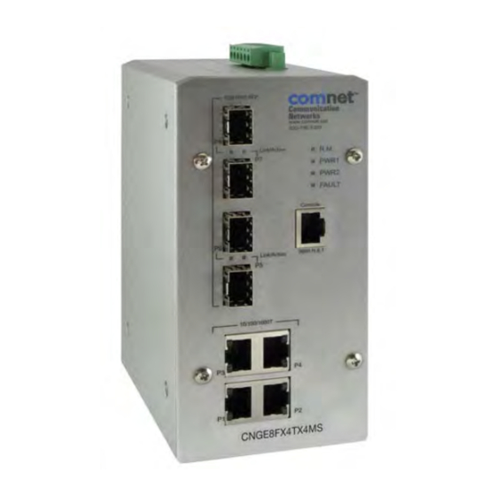
The ComNet™ CNGE8FX4TX4MS Managed Ethernet Switch provides
transmission of (4) 100/1000 BASE-TX and (4) 10/100/1000FX combo ports.
Unlike most Ethernet switches, these environmentally hardened units are
designed for deployment in difficult operating environments, and are available
for use with either conventional CAT-5e copper or optical transmission media.
Ports 1 – 4 support the 10/100/1000 Mbps Ethernet IEEE 802.3 protocol, and
auto-negotiating and auto-MDI/MDIX features are provided for simplicity and
ease of installation. Ports 5 – 8 are 10/100/1000 configurable for copper or
100/1000 fiber media for use with multimode or single mode optical fiber
without need for configuration, selected by optional SFP modules. These
network managed layer 2 switches are optically and electrically compatible
with any IEEE 802.3 compliant Ethernet devices. Plug-and-play design
ensures ease of installation, and no electrical or optical adjustments are ever
required. The CNGE8FX4TX4MS incorporates LED indicators for monitoring the
operating status of the managed switch and network.
Advertisement
Table of Contents

Related Manuals for Comnet CNGE8FX4TX4MS


Summary of Contents for Comnet CNGE8FX4TX4MS
- Page 1 2 switches are optically and electrically compatible with any IEEE 802.3 compliant Ethernet devices. Plug-and-play design ensures ease of installation, and no electrical or optical adjustments are ever required. The CNGE8FX4TX4MS incorporates LED indicators for monitoring the operating status of the managed switch and network.
-
Page 2: Table Of Contents
Content Overview ..........................1 Introduction...........................1 ComNet CNGE8FX4TX4MS Features...................4 CNGE8FX4TX4MS Technical Specifications ................6 Packing List ..........................8 Safety Precaution..........................8 Hardware Description......................9 Front Panel............................9 Top View .............................10 Wiring the Power Inputs......................10 LED Indicators ..........................12 ... - Page 3 Console Management ....................... 24 Connecting to the Console Port ....................24 Pin Assignment ...........................25 Login through the Console Interface ..................26 CLI Management ........................28 System Commands Set.......................... 30 Port Commands Set ..........................32 Trunk Commands Set ..........................34 ...
- Page 4 TFTP – Firmware Update ......................59 TFTP – Restore Configuration.....................59 TFTP - Backup Configuration .....................60 System Event Log – Syslog Configuration .................61 System Event Log - SMTP Configuration ...................62 System Event Log - Event Configuration..................63 ...
- Page 5 QoS Configuration ........................92 QoS Policy and Priority Type ......................... 92 Port Base Priority ........................... 94 COS Configuration ..........................94 TOS Configuration..........................94 IGMP Configuration ........................95 X-Ring ............................97 LLDP Configuration........................99 Security .............................100 ...
-
Page 7: Overview
Overview Introduction To create reliability in your network, the ComNet CNGE8FX4TX4MS 4 10/100/1000T + 4 SFP Managed Switch comes equipped with a proprietary redundant network protocol—X-Ring provides users with an easy way to establish a redundant Ethernet network with ultra high-speed recovery time less than 20ms. - Page 8 P-Fail LED will turn on and send an alarm through a relay output to notify the user. Flexible Mounting The CNGE8FX4TX4MS is a compact size and can be mounted on a DIN-rail or panel. It can be used in any location where space is scarce. Advanced Protection...
- Page 9 Easy Troubleshooting LED indicators make troubleshooting quick and easy. Each 10/100/1000 Base-TX port has 2 LEDs that display the link status and transmission speed. The three power indicators: PWR1, PWR2 and P-Fail assist in diagnosing any problems quickly.
-
Page 10: Comnet Cnge8Fx4Tx4Ms Features
ComNet CNGE8FX4TX4MS Features Provides four 10/100/1000Base-T Mbps Ethernet ports Provides four SFP (mini-GBIC) port (supports 100/1000 Mbps Dual Mode) SFPs support DMI function Supports full/half duplex flow control Supports auto-negotiation Supports MDI/MDI-X auto-crossover Supports Packet Buffer up to 1Mb ... - Page 11 Bandwidth Control Ingress Packet Filter and Egress Rate Limit Broadcast/Multicast Packet Filter Control Port Mirror: Monitor traffic in switched networks. TX Packet only RX Packet only Both of TX and RX Packet System Event Log System Log Server/Client SMTP e-mail Alert Relay Alarm Output System Events Security...
-
Page 12: Cnge8Fx4Tx4Ms Technical Specifications
CNGE8FX4TX4MS Technical Specifications Communication Compatibility IEEE 802.3, 802.3u, 802.3ab IEEE 802.3x, 802.3z, 802.3ad IEEE 802.1d, 802.1p, 802.1Q, 802.1x IEEE 802.1ab 10/100/1000Base-T, 1000Base-X Transmission Speed Up to 1000 Mbps Interface Connectors 4 x RJ45 (4-port 10/100/1000TX) 4 x 100/1000 SFP sockets 6-pin removable screw terminal (Power &... - Page 13 Diagnostics Port Mirroring, Real-time traffic statistic, MAC Address Table, SNTP, Syslog, E-Mail Alert, SNMP, Trap, RMON Power Power Consumption 13 Watts Power Input 2 x Unregulated +12 ~ 48 V Fault Output 1 Relay Output Mechanism Dimensions (WxHxD) 59.6 x 152 x 105 mm Enclosure IP-30, Metal shell with solid mounting kits Mounting...
-
Page 14: Packing List
CE EN61000-4-5 (Surge) CE EN61000-4-6 (CS) CE EN61000-4-8 (Magnetic Field) CE EN61000-4-11 (Voltage DIP) CE EN61000-3-2 (Harmonics Current) CE EN61000-3-3 (Voltage Fluctuation & Flickers) Free Fall IEC60068-2-32 Shock IEC60068-2-27 Vibration IEC60068-2-6 Packing List 1 x 4 10/100/1000T + 4 SFP Managed Switch ... -
Page 15: Hardware Description
Hardware Description In this section, we will introduce the CNGE8FX4TX4MS’s hardware spec, port, cabling information, and wiring installation. Front Panel The Front Panel of the CNGE8FX4TX4MS is shown as follows: Front Panel of the CNGE8FX4TX4MS Managed Switch... -
Page 16: Top View
Top View The top panel of the CNGE8FX4TX4MS is equipped with one terminal block connector for two DC power inputs. Top panel of the 4 10/100/1000T + 4 SFP Switch Wiring the Power Inputs Primary Secondary (Redundant) Voltage Input Power Input Insert the positive and negative wires into the V+ and V- contacts on the terminal block connector. - Page 17 Tighten the wire-clamp screws to prevent the wires from loosening. Note The wire gauge for the terminal block should be in the range between 12~ 20 AWG.
-
Page 18: Led Indicators
LED Indicators There are LEDs that display the power status and network status and are located on the front panel of the CNGE8FX4TX4MS switch. Each has its own specific meaning as noted below. Color Description The switch is the master of the X-ring group... -
Page 19: Ports
Ports RJ45 ports (Auto MDI/MDIX): The RJ45 ports are auto-sensing for 10Base-T, 100Base-TX or 1000Base-T device connections. Auto MDI/MDIX means that you can connect to another switch or workstation without changing straight through or crossover cabling. See figures below for straight-through and crossover cable schematic. RJ45 Pin Assignments ... -
Page 20: Cabling
Straight Through Cable Schematic Cross Over Cable Schematic Cabling Use the four twisted-pair, Category 5e or above cabling for all RJ45 port connections. The length of cable between the switch and the link partner (switch, hub, workstation, etc.) must be less than 100 meters (328 ft.) long. The small form-factor pluggable (SFP) devices that are the compact optical transceivers used for optical communication for both telecommunication and data communication applications. - Page 21 SFP Inserted Insert the fiber cable of LC connector into the SFP. LC connector to the SFP To remove the LC connector from the SFP, please follow the steps shown below: Press the upper side of the LC connector from the SFP and pull it out to release. Remove LC connector...
- Page 22 Push down the metal loop and pull the SFP out by the plastic part. Pull out from the SFP receptacle...
-
Page 23: Din-Rail Mounting Installation
DIN-Rail Mounting Installation The DIN-Rail mount is attached to the CNGE8FX4TX4MS at the factory. If the DIN-Rail is not attached to the switch, please see the following to attach the DIN-Rail to the switch. Insert the screws to attach the DIN-Rail to the switch. - Page 24 Insert the top of DIN-Rail into the track. Lightly push the button of DIN-Rail mount into the track. Check the switch is held securely on the track. To remove the switch from the track, reverse the above steps.
-
Page 25: Wall Mount Plate Mounting
Wall Mount Plate Mounting Follow the steps as below to mount the switch with the wall mount plate. Remove the DIN-Rail from the switch; loosen the screws to remove the DIN-Rail mount. Place the wall mount plate on the rear panel of the switch. Use the screws to screw the wall mount plate on the switch. -
Page 26: Hardware Installation
Hardware Installation This section describes how to install the CNGE8FX4TX4MS Switch and the installation steps. Installation Steps Unpack the switch from carton. Check the DIN-Rail is screwed on the Switch. If the DIN-Rail mount is not attached to the switch, please refer to DIN-Rail Mounting section for DIN-Rail mounting installation. -
Page 27: X-Ring Application
X-Ring Application The switch supports the X-Ring protocol that can help the network recover from network connection failure within 20ms or less, and make the network system more reliable. The X-Ring algorithm is similar to Spanning Tree Protocol (STP) and Rapid STP (RSTP) algorithm but its recovery time is less than STP/RSTP. -
Page 28: Coupling Ring Application
Coupling Ring Application In the network, it may be necessary to have more than one X-Ring group. By using the coupling function it is possible to connect each X-Ring for a redundant backup. This will ensure the transmission between two ring groups will not fail. The following figure is an example of the coupling ring feature. -
Page 29: Dual Homing Application
Dual Homing Application The Dual Homing function is designed to prevent a connection loss between the X-Ring group and an upper level/core switch. By assigning two ports on the switches as Dual Homing ports, they will become the designated backup ports in the X-Ring group. The Dual Homing function only works when the X-Ring function is made active. -
Page 30: Console Management
Console Management Connecting to the Console Port The cable supplied with the switch has an RS232 connector on one end and the other end is an RJ45 connector. Attach the end of the RS232 connector to a PC or terminal and the other end of RJ45 connector to the console port of switch. -
Page 31: Pin Assignment
Pin Assignment RJ45 Connector Connector Orange/White Orange Green/White Blue Blue/White Green Brown/White Brown... -
Page 32: Login Through The Console Interface
Login through the Console Interface When the switch and PC are connected, turn on the PC and run a terminal emulation program or Hyper Terminal and configure the communication parameters to match the following default characteristics of the console port: Baud Rate: 9600 bps Data Bits: 8 Parity: none... - Page 33 name and Password (use Enter key to switch), then press Enter key and the Main Menu of console management appears. See below figure for login screen. Console login interface...
-
Page 34: Cli Management
CLI Management The system supports the console management – CLI command. After you login to the system, you will see a command prompt. To enter CLI management interface, type in ‘enable’ command. CLI command interface... - Page 35 Commands Level The following table lists the CLI commands and description. Access Modes Prompt Exit Method About This Mode1 Method The user commands available at the user level are a subset of those Begin a Enter logout or available at the privileged level. session with User EXEC switch>...
-
Page 36: System Commands Set
System Commands Set Command Level Description Example show config Show switch switch>show config configuration show terminal Show console switch#show terminal information write memory Save user configuration switch#write memory into permanent memory (flash rom) Configure system name system name switch(config)#system name xxx [System Name] Set switch system system location... - Page 37 Show administrator show admin switch#show admin information dhcpserver enable Enable DHCP Server switch(config)#dhcpserver enable Dhcpserver disable Disable DHCP Server switch(config)#no dhcpserver dhcpserver lowip Configure low IP switch(config)#dhcpserver lowip address for IP pool [Low IP] 192.168.1.100 dhcpserver highip Configure high IP switch(config)#dhcpserver highip address for IP pool [High IP]...
-
Page 38: Port Commands Set
Set the IP security list security ip switch(config)#security ip 1 [Index(1..10)] [IP 192.168.1.55 Address] show security Show the information of switch#show security IP security no security Disable IP security switch(config)#no security function Disable IP security of no security http switch(config)#no security http HTTP server no security telnet Disable IP security of... - Page 39 no security Disable security of switch(config)#interface fastEthernet interface switch(config-if)#no security bandwidth type all Set interface ingress switch(config)#interface fastEthernet limit frame type to ‘accept all frame’ switch(config-if)#bandwidth type all bandwidth type Set interface ingress switch(config)#interface fastEthernet limit frame type to broadcast-multicast-floo ‘accept broadcast, ded-unicast switch(config-if)#bandwidth type...
-
Page 40: Trunk Commands Set
bandwidth control switch(config-if)#show bandwidth state Use the state interface switch(config)#interface fastEthernet configuration command [Enable | Disable] to specify the state switch(config-if)#state Disable mode of operation for Ethernet ports. Use the disable form of this command to disable the port. show interface show interface switch(config)#interface fastEthernet configuration status... - Page 41 [GroupID] :1~4 lacp [Port-list]:Member port switch(config)#aggregator group 2 workp list, This parameter 1,4,3 lacp workp 3 [Workport] could be a port range(ex.1-4) or a port list separate by a comma(ex.2, 3, 6) [Workport]: The amount of work ports, this value could not be less than zero or be large than the amount of member...
-
Page 42: Dmi Commands Set
DMI Commands Set Command Level Description Example Show DMI port status show dmi switch(config)#interface fastEthernet (Port 5 to port 8 supports DMI fuction) switch(config-if)#show dmi VLAN Commands Set Command Level Description Example vlan database Enter VLAN configure switch#vlan database mode To set switch VLAN Vlanmode switch(vlan)#vlanmode portbase... - Page 43 belong to a trunk group, this command can’t be applied. vlan 8021q port Assign a trunk link for switch(vlan)#vlan 8021q port 3 [PortNumber] VLAN by port, if the port trunk-link tag 2,3,6,99 trunk-link tag belong to a trunk group, [TaggedVID List] this command can’t be switch(vlan)#vlan 8021q port 3 applied.
-
Page 44: Spanning Tree Commands Set
Spanning Tree Commands Set Command Level Description Example Enable spanning tree spanning-tree enable switch(config)#spanning-tree enable Configure spanning tree spanning-tree priority switch(config)#spanning-tree priority priority parameter [0~61440] 32767 spanning-tree max-age Use the spanning-tree switch(config)#spanning-tree [seconds] max-age global max-age 15 configuration command to change the interval between messages the spanning tree receives from the root switch. - Page 45 each of the listening learning states last before the port begins forwarding. stp-path-cost Use the spanning-tree switch(config)#interface fastEthernet cost interface [1~200000000] configuration command switch(config-if)#stp-path-cost 20 to set the path cost for Spanning Tree Protocol (STP) calculations. In the event of a loop, spanning tree considers the path cost when selecting...
-
Page 46: Qos Commands Set
Admin NonSTP of STP stp-admin-non-stp switch(config)#interface fastEthernet priority on this interface. [True|False] switch(config-if)#stp-admin-non-stp False show spanning-tree Displays a summary of switch>show spanning-tree the spanning-tree states. no spanning-tree Disable spanning-tree. switch(config)#no spanning-tree QOS Commands Set Command Level Description Example Select QOS policy qos policy switch(config)#qos policy scheduling... -
Page 47: Igmp Commands Set
IGMP Commands Set Command Level Description Example igmp enable Enable IGMP snooping switch(config)#igmp enable function Set IGMP query to auto igmp query auto switch(config)#igmp query auto mode Set IGMP query to force igmp query force switch(config)#igmp query force mode Displays the details of Show igmp switch#show igmp configuration an IGMP configuration. -
Page 48: Snmp Commands Set
[MAC] interface (static) switch(config-if)#no mac-address-table static hwaddr 000012345678 Remove an entry of no mac-address-table switch(config)#no mac-address-table MAC address table filter hwaddr filter hwaddr 000012348678 (filter) [MAC] no mac-address-table Remove dynamic entry switch(config)#no mac-address-table of MAC address table SNMP Commands Set Command Level Description... - Page 49 snmpv3 user Configure the switch(config)#snmpv3 user test01 userprofile for SNMPV3 [User Name] group G1 password AuthPW PrivPW agent. Privacy group password could be [Group Name] empty. password [Authentication Password] [Privacy Password] snmpv3 access Configure the access switch(config)#snmpv3 access table of SNMPV3 agent context-name [Context context-name Test group G1...
- Page 50 [User Name] of SNMPv3 agent. Remove specified no snmpv3 access switch(config)#no snmpv3 access access table of context-name [Context context-name Test group G1 SNMPv3 agent. Name ] security-level AuthPr group iv match-rule Exact views V1 V1 V1 [Group Name ] security-level [NoAuthNoPriv|AuthNoP riv|AuthPriv] match-rule...
-
Page 51: Port Mirroring Commands Set
Port Mirroring Commands Set Command Level Description Example monitor rx Set RX destination port switch(config)#monitor rx of monitor function monitor tx Set TX destination port switch(config)#monitor tx of monitor function Show port monitor show monitor switch#show monitor information monitor Configure source port switch(config)#interface fastEthernet of monitor function [RX|TX|Both]... - Page 52 accountport account port global accountport 1816 configuration command [port ID] to change the accounting port 8021x system sharekey Use the 802.1x system switch(config)# 8021x system share key global [ID] sharekey 123456 configuration command to change the shared key value. Use the 802.1x system 8021x system nasid switch(config)# 8021x system nasid nasid global...
-
Page 53: Tftp Commands Set
Use the 802.1x misc 8021x misc maxrequest switch(config)# 8021x misc max request global [number] maxrequest 3 configuration command to set the MAX requests. Use the 802.1x misc 8021x misc switch(config)# 8021x misc reauth period global reauthperiod [sec.] reauthperiod 3000 configuration command to set the reauth period. -
Page 54: Systemlog, Smtp And Event Commands Set
SystemLog, SMTP and Event Commands Set Command Level Description Example Set System log server systemlog ip switch(config)# systemlog ip IP address. [IP address] 192.168.1.100 Specified the log mode systemlog mode switch(config)# systemlog mode both [client|server|both] Displays system log. show systemlog Switch>show systemlog show systemlog Show system log client... - Page 55 event systemlog Set port event for switch(config)#interface fastethernet system log [Link-UP|Link-Down|Bot switch(config-if)#event systemlog both Set port event for SMTP event smtp switch(config)#interface fastethernet [Link-UP|Link-Down|Bot switch(config-if)#event smtp both Show event selection show event switch#show event Disable cold start event no event switch(config)#no event type device-cold-start...
-
Page 56: Sntp Commands Set
SNTP Commands Set Command Level Description Example Enable SNTP function sntp enable switch(config)#sntp enable sntp daylight Enable daylight saving switch(config)#sntp daylight time, if SNTP function is inactive, this command can’t be applied. sntp daylight-period Set period of daylight switch(config)# sntp daylight-period saving time, if SNTP [Start time] [End time] 20060101-01:01 20060202-01-01... -
Page 57: X-Ring Commands Set
X-ring Commands Set Leve Command Description Example ring enable Enable X-ring switch(config)#ring enable ring master Enable ring master switch(config)#ring master ring couplering Enable couple ring switch(config)#ring couplering ring dualhoming Enable dual homing switch(config)#ring dualhoming Configure 1st/2nd Ring ring ringport switch(config)#ring ringport 7 8 [1st Ring Port] [2nd Ring Port Port]... -
Page 58: Web-Based Management
Web-Based Management About Web-based Management On CPU board of the switch there is an embedded HTML web site residing in the flash memory. This Graphic User Interface (GUI) offers advanced management features and allows users to manage the switch from anywhere on the network through a standard browser such as Microsoft Internet Explorer. -
Page 59: System Login
System Login Launch Internet Explorer on the PC Enter ‘http:// and the default IP address in the browser address bar. Press Enter or Return. The login screen will appear. Enter the user name and password. The default user name and password are the same: admin Press Enter or OK, and then the home screen of the Web-based management appears as shown below:... -
Page 60: Main Interface
Main interface Main interface... -
Page 61: System Information
System Information Assigning the system name, location and viewing the system information System Name: Assign the name of switch. The maximum length is 64 bytes System Description: Displays the description of switch. This is Read only and cannot be modified System Location: Assign the switch physical location. - Page 62 IP Configuration To configure the IP Settings and DHCP client function DHCP Client: When DHCP client function is enabled, the switch will be assigned an IP address from the network DHCP server. The default IP address will be replaced by the DHCP server assigned IP address.
-
Page 63: Dhcp Server - System Configuration
DHCP Server – System configuration The system provides the DHCP server function to enable the DHCP server function, the switch system will be a DHCP server. DHCP Server: Enable – the switch will become the DHCP server on your local network. ... -
Page 64: Dhcp Client - System Configuration
DHCP Client – System Configuration When the DHCP server function is active, the system will collect the DHCP client information and display it here. DHCP Client Entries interface DHCP Server - Port and IP Bindings You can assign the specific IP address that is the IP address in dynamic IP address assignment range to the specific port. -
Page 65: Tftp - Firmware Update
TFTP – Firmware Update It provides the functions to allow a user to update the switch’s firmware. Before updating, make sure you have your TFTP server ready and the firmware image is on the TFTP server. TFTP Server IP Address: fill in your TFTP server IP. Firmware File Name: the name of firmware file. -
Page 66: Tftp - Backup Configuration
TFTP - Backup Configuration You can save current EEPROM value from the switch to the TFTP server. You can then go to the TFTP restore configuration page to restore the EEPROM value. TFTP Server IP Address: Enter the TFTP server IP address Backup File Name: Enter the file name Select Backup Configuration interface... -
Page 67: System Event Log - Syslog Configuration
System Event Log – Syslog Configuration Configuring the system event mode that can be collected and the system log server IP address. Syslog Client Mode: select the system log mode – client only, server only, or both client and server. System Log Server IP Address: assigns the system log server IP address. -
Page 68: System Event Log - Smtp Configuration
System Event Log - SMTP Configuration You can set up the mail server IP address, Email address accounts, account passwords, and forwarded Email accounts for receiving the event alert. Email Alert: enable or disable the Email alert function. SMTP Server IP: set up the mail server IP address (when Email Alert is enabled, this function will then be available). -
Page 69: System Event Log - Event Configuration
System Event Log - Event Configuration You can select the system log events and SMTP events. When selected events occur, the system will send out the event log information. Also, event per port log and SMTP events can be selected. After configure, select System event selection: Four selections –... -
Page 70: Fault Relay Alarm
Port event selection: select the per port events and per port SMTP events. It has three selections – 1) Link UP, 2) Link Down, and 3) Link UP & Link Down. Disable means no event is selected. Link UP: the system will issue a log message when port connection is up only. ... -
Page 71: Sntp Configuration
SNTP Configuration You can configure the SNTP (Simple Network Time Protocol) settings. The SNTP allows you to synchronize the switch’s clocks through the internet website. SNTP Client: enable or disable SNTP function to get the time from the SNTP server. Daylight Saving Time: enable or disable daylight savings time function. - Page 72 Local Time Zone Conversion from UTC Time at 12:00 UTC November Time Zone - 1 hour 11am Oscar Time Zone -2 hours 10 am ADT - Atlantic Daylight -3 hours 9 am AST - Atlantic Standard -4 hours 8 am EDT - Eastern Daylight EST - Eastern Standard -5 hours...
- Page 73 SNTP Server URL: set the SNTP server IP address. Daylight Saving Period: set up the Daylight Saving beginning date and Daylight Savings ending date. Both will be different in every year. Daylight Savings Offset (mins): set the offset time. Switch Timer: Displays the current switch time. Select SNTP Configuration interface...
-
Page 74: Ip Security
IP Security The IP security function allows user to assign 10 specific IP addresses that have permission to access the switch through the web browser for the securing switch management. IP Security Mode: when this option is in the Enable mode, the Enable HTTP Server ... -
Page 75: User Authentication
User Authentication Change the default web management login user name and password for security management. User name: Enter the new user name (The default is admin) Password: Enter the new password (The default is admin) Confirm password: Re-type the new password And then, select User Authentication interface... -
Page 76: Port Statistics
Port Statistics The following information provides current port information statistics. Port: The port number. Type: Displays the current connection speed of the port. Link: The linkstatus — port is ‘Up’ or ‘Down’. State: Set by Port Control. When the state is disabled, the port will not transmit or ... -
Page 77: Port Control
Port Control In Port Control, you can view the status of every port status that depends on the user setting and the negotiation result. Port: select the port that you want to configure. State: Current port status. The port can be set to disable or enable mode. If the port setting is disabled then it will not receive or transmit any packet. -
Page 78: Port Trunk
Port Trunk The Link Aggregation Control Protocol (LACP) provides a standardized means for exchanging information between Partner Systems on a link to allow their Link Aggregation Control instances to reach agreement on the identity of the Link Aggregation Group to which the link belongs. -
Page 79: Aggregator Information
Select button to delete the Trunk Group. Select the Group ID and select Port Trunk—Aggregator Setting interface Aggregator Information When you set the aggregator setting with LACP disabled, the local static trunk group information will be displayedhere. Port Trunk – Aggregator Information interface... -
Page 80: State Activity
State Activity When you setup the LACP aggregator, you can configure port state activity. You can select or deselect the port. When you mark the port and select button the port state activity will change to Active. Opposite is Passive. Active: The port automatically sends LACP protocol packets. -
Page 81: Port Mirroring
Port Mirroring The Port mirroring is a method for monitoring traffic in switched networks. Traffic through the ports can be monitored by one specific port. That means traffic that goes in or out monitored (source) ports will be duplicated into a mirror (destination) port. Destination Port: There is only one port can be selected to be the destination (mirror) ... -
Page 82: Rate Limiting
Rate Limiting You can set up every port’s bandwidth rate and frame limitation type. Ingress Limit Frame type: select the frame type that wants to filter. The frame types have four options for selecting: 1) All, 2) Broadcast/Multicast/Flooded Unicast, 3) Broadcast/Multicast and 4) Broadcast only. -
Page 83: Dmi (Digital Monitoring Interface)
DMI (Digital Monitoring Interface) You can see the transceiver’s status by ports and set up an action when detecting the exceptional value. The action includes the following options. Off: The port will be shut down when detecting the exceptional value. ... -
Page 84: Vlan Configuration
VLAN configuration A Virtual LAN (VLAN) is a logical network grouping that limits the broadcast domain, that would allow you to isolate network traffic. Only the members of the VLAN will receive traffic from the same members of VLAN. Basically, creating a VLAN from a switch is the logical equivalent of reconnecting a group of network devices to another Layer 2 switch. -
Page 85: Vlan Configuration - Port-Based Vlan
VLAN configuration - Port-based VLAN Packets can go among only members of the same VLAN group. Note all unselected ports are treated as belonging to another single VLAN. If the port-based VLAN is enabled, the VLAN-tagging is ignored. In order for an end station to send packets to different VLAN groups, it has to be either capable of tagging packets it sends with VLAN tags or attached to a VLAN-aware bridge that is capable of classifying and tagging the packet with different VLAN ID based on not only default PVID but also other information about the packet, such as the protocol. - Page 86 VLAN—Port Based Add interface You will see the VLAN displays. button to delete an unwanted VLAN. button to modify an existing VLAN group. Note Remember to execute the ‘Save Configuration’ action, otherwise the new configuration will be lost when switch is powered off.
-
Page 87: 802.1Q Vlan
802.1Q VLAN A tagged-based VLAN is an IEEE 802.1Q specification standard. Therefore, it is possible to create a VLAN across devices from different switch venders. An IEEE 802.1Q VLAN uses a technique to insert a ‘tag’ into the Ethernet frames. The tag contains a VLAN Identifier (VID) that indicates the VLAN numbers. - Page 88 802.1Q Configuration Enable GVRP Protocol: Select the check box to enable GVRP protocol. Select the port that needs to be configured. Link Type: there are three types of link: Access Link: a single switch only, allows user to select group ports by setting the ...
- Page 89 Group Configuration interface You can change the VLAN group name and VLAN ID. Select Group Configuration interface...
-
Page 90: Rapid Spanning Tree
Rapid Spanning Tree Rapid Spanning Tree Protocol (RSTP) is an evolution of the Spanning Tree Protocol and provides for faster spanning tree convergence after a topology change. The system also supports STP and the system will auto detect the connected device that is running STP or RSTP protocol. -
Page 91: Rstp - Port Configuration
RSTP System Configuration interface RSTP - Port Configuration You can configure path cost and priority of every port. Select the port in Port column. Path Cost: The cost of the path to the other bridge from this transmitting bridge at the specified port. - Page 92 status of the link to be manipulated administratively. True is P2P enabling. False is P2P disabling. Edge: The port directly connected to the end stations cannot create a bridging loop in the network. To configure the port as an edge port, set the port to True status. Non STP: The port includes the STP mathematic calculation.
-
Page 93: Snmp Configuration
SNMP Configuration Simple Network Management Protocol (SNMP) is the protocol developed to manage nodes (servers, workstations, routers, switches and hubs etc.) on an IP network. SNMP enables network administrators to manage network performance, find and solve network problems, and plan for network growth. Network management systems learn of problems by receiving traps or change notices from network devices implementing SNMP. -
Page 94: Trap Configuration
SNMP System Configuration interface Trap Configuration A trap manager is a management station that receives traps – the system alerts generated by the switch. If no trap manager is defined, no traps will be issued. Create a trap manager by entering the IP address of the station and a community string. -
Page 95: Snmpv3 Configuration
Trap Managers interface SNMPV3 Configuration Configure the SNMP V3 function. Context Table Configure SNMP v3 context table. Assign the context name of context table. Select add context name. Select to remove unwanted context name. User Profile Configure SNMP v3 user table.. User ID: set up the user name. - Page 96 SNMP V3 configuration interface Group Table Configure SNMP v3 group table. Security Name (User ID): Assign the user name that you have set up in user table. Group Name: Set up the group name. Select to add context name. ...
- Page 97 Access Table Configure SNMP v3 access table. Context Prefix: Set up the context name. Group Name: Set up the group. Security Level: Set up the access level. Context Match Rule: Select the context match rule. Read View Name: Set up the read view. ...
-
Page 98: Qos Configuration
QoS Configuration You can configure QoS policy and priority setting, per port priority setting, COS and TOS setting. QoS Policy and Priority Type QoS Policy: select the QoS policy rule. Use an 8,4,2,1 weighted fair queuing scheme: The switch will follow 8:4:2:1 rate ... - Page 99 QoS Configuration interface...
-
Page 100: Port Base Priority
Port Base Priority Configure the per port priority level. Port: each port has 4 priority levels – high, middle, low, and lowest. Select COS Configuration Set up the COS priority level. COS priority: Set up the COS priority level 0~7 –high, middle, low, lowest. ... -
Page 101: Igmp Configuration
IGMP Configuration The Internet Group Management Protocol (IGMP) is an internal protocol of the Internet Protocol (IP) suite. The IP suite manages multicast traffic by using switches, routers, and hosts that support IGMP. Enabling IGMP allows the ports to detect IGMP queries, report packets and manage IP multicast traffic through the switch. - Page 102 IGMP Protocol: Enable or disable the IGMP protocol. IGMP Query: Select the IGMP query function as Enable or Auto to set the switch as a querier for IGMP version 2 multicast network. Select IGMP Configuration interface...
-
Page 103: X-Ring
X-Ring X-Ring provides a faster redundant recovery than Spanning Tree topology. The action is similar to STP or RSTP, but the algorithms not the same. In the X-Ring topology, every switch should enable the X-Ring function and assign two member ports in the ring. Only one switch in the X-Ring group would be set as a master switch that would be blocked, called the backup port, and another port is called the working port. - Page 104 Enable Coupling Ring: To enable the coupling ring function, select the check box that enables the coupling ring function. Coupling port: Assign the member port. Control port: Set the switch as the master switch in the coupling ring. ...
-
Page 105: Lldp Configuration
LLDP Configuration Link Layer Discovery Protocol (LLDP) is defined in the IEEE 802.1AB, it is an emerging standard which provides a solution for the configuration issues caused by expanding LANs. LLDP specifically defines a standard method for Ethernet network devices such as switches, routers and wireless LAN access points to advertise information about themselves to other nodes on the network and store the information they discover. -
Page 106: Security
Security 802.1X/Radius Configuration 802.1x is an IEEE authentication specification that allows a client to connect to a wireless access point or wired switch but prevents the client from gaining access to the Internet until it provides authority, like a user name and password that are verified by a separate server. System Configuration After enabling the IEEE 802.1X function, you can configure the parameters of this function. - Page 107 802.1x Per Port Configuration You can configure a 802.1x authentication state for each port. This state provides Disable, Accept, Reject and Authorize. Use Space key to change the state value. Reject: the specified port is required to be held in the unauthorized state. ...
- Page 108 Miscellaneous Configuration Quiet Period: set the period during which the port doesn’t try to acquire a supplicant. TX Period: set the period the port wait for retransmit next EAPOL PDU during an authentication session. Supplicant Timeout: set the period of time the switch waits for a supplicant response to an EAP request.
-
Page 109: Mac Address Table
MAC Address Table Use the MAC address table to ensure the port security. Static MAC Address You can add a static MAC address; it remains in the switch's address table, regardless of whether the device is physically connected to the switch. This saves the switch from having to re-learn a device's MAC address when the disconnected or powered-off device is active on the network again. - Page 110 MAC Filtering By filtering MAC addresses, the switch can easily filter pre-configure MAC addresses and reduce the un-safety. You can add and delete filtering MAC addresses. MAC Filtering interface MAC Address: Enter the MAC address that you want to filter. Select If you want to delete the MAC address from filtering table, select the MAC address and select...
- Page 111 All MAC Addresses You can view the port that connects a device’s MAC address and related devices’ MAC addresses. Select the port. The selected port of the static MAC addresses information will be displayed here. Select to clear the current port’s static MAC address information on screen. All MAC Address interface...
- Page 112 Multicast Filtering Multicasts are similar to broadcasts, they are sent to all end stations on a LAN or VLAN. Multicast filtering is the function, which end stations can receive the multicast traffic if the connected ports had been included in the specific multicast groups. With multicast filtering, network devices only forward multicast traffic to the ports that are connected to the registered end stations.
-
Page 113: Factory Default
Factory Default To reset switch to the default configuration, select to reset all switch configurations to the default value. Factory Default interface Save Configuration Save all configuration changes that you have made in the system. To ensure that all configuration changes will be saved, select to save all the changes to the flash memory. -
Page 114: Help
problem with the power cord. Check for loose power connections, power losses or surges at the power outlet. If you still cannot resolve the problem, contact ComNet for assistance. If the ComNet switch LED indicators are normal while the cables are correctly connected, ... - Page 115 ComNet Customer Service Customer Care is ComNet Technology’s global service center, where our professional staff is ready to answer your questions at any time. Email address of ComNet Global Service Center: customercare@ComNet.net Communication Networks World Headquarters ComNet Europe Ltd 3 Corporate Drive...
Need help?
Do you have a question about the CNGE8FX4TX4MS and is the answer not in the manual?
Questions and answers