Table of Contents
Advertisement
Quick Links
INSTALLATION AND OPERATION MANUAL
CNGE3FE7MS4
ELECTRICAL SUBSTATION-RATED
MANAGED ETHERNET SWITCH WITH (7) 10/100T(X)
+ (3) CONFIGURABLE 10/100/1000T(X)/100/1000FX PORTS
The ComNet
CNGE3FE7MS4 is a substation-rated and industrially hardened fully
™
managed layer 2 gigabit Ethernet switch. Fully compliant with the requirements of IEC
61850-3, IEEE 1613 Class 2, UL 508 Class 1/ Division 2 (Groups A, B, C, & D for hazardous
environments), EN50155, and NEMA TS-1/ TS-2, it is designed for deployment
in environments where high levels of electromagnetic noise and interference
(EMI) and severe voltage transients and surges are routinely encountered, such as
electrical utility substations and switchyards, heavy manufacturing facilities, trackside
and roadside electronic equipment, and other difficult out-of-plant applications.
Providing (7) 10/100 BASE-TX ports, the (3) 10/100/1000TX or 100/1000BASE-FX
user-configurable combo gigabit uplink ports support conventional CAT-5e/CAT-6
copper or optical transmission media by selection of the appropriate ComNet SFP
module. Featuring an internal/self-contained 85-264 VAC/88-373 VDC power supply,
the CNGE3FE7MS4 is DIN-rail or wall-mountable, and is ideal for mission-critical
applications where very high levels of reliability and network availability are of
the utmost importance. Utilizing exclusive ComNet C-Ring technology, the fastest
recovery redundant ring available, network recovery time of <10 ms is provided
for protection from network faults or temporary interruptions. ComChain permits
additional redundant network rings of different redundancy protocols to function
together as a larger and more robust network topology. eConsole, a Windows-based
utility, is included for centralized/remote management and configuration of all
functions of the CNGE3FE7MS4.
Rev. 4.30.14
Advertisement
Table of Contents

Related Manuals for Comnet CNGE3FE7MS4


Summary of Contents for Comnet CNGE3FE7MS4
- Page 1 Providing (7) 10/100 BASE-TX ports, the (3) 10/100/1000TX or 100/1000BASE-FX user-configurable combo gigabit uplink ports support conventional CAT-5e/CAT-6 copper or optical transmission media by selection of the appropriate ComNet SFP module. Featuring an internal/self-contained 85-264 VAC/88-373 VDC power supply, the CNGE3FE7MS4 is DIN-rail or wall-mountable, and is ideal for mission-critical applications where very high levels of reliability and network availability are of the utmost importance.
-
Page 2: Table Of Contents
Introduction Software Features Hardware Features Safety Indications Hardware Installation Installing Switch on DIN-Rail Mount Series on DIN-Rail Wall Mounting Installation Mounting the CNGE3FE7MS4 on a Wall Hardware Overview Front Panel Front Panel LEDs Wiring Grounding Fault Relay Redundant Power Inputs... - Page 3 INSTALLATION AND OPERATION MANUAL CNGE3FE7MS4 Preparing for Web Management System Login Main Interface System Information System Information Enable Location Alert Basic setting Switch Setting Admin & Password IP Setting Time Setting PTP Client LLDP Auto Provision Backup & Restore Upgrade Firmware...
- Page 4 INSTALLATION AND OPERATION MANUAL CNGE3FE7MS4 RSTP RSTP setting MSTP Multicast Static Multicast Filtering VLAN VLAN Setting - IEEE 802.1Q VLAN Setting – Port Based SNMP SNMP – Agent Setting SNMPV3 SNMP –Trap Setting Traffic Prioritization QoS policy Port-base priority COS/802.1p...
- Page 5 INSTALLATION AND OPERATION MANUAL CNGE3FE7MS4 System Event Log Save Configuration Factory Default System Reboot Command Line Interface Management About CLI Management CLI Management by Telnet Commands Level Symbol of Command Level Commands Set List—System Commands Set Commands Set List—Port Commands Set Commands Set List—Trunk command set...
-
Page 6: Regulatory Compliance Statement
ComNet warrants that all ComNet products are free from defects in material and workmanship for a specified warranty period from the invoice date for the life of the installation. ComNet will repair or replace products found by ComNet to be defective within this warranty period, with shipment expenses apportioned by ComNet and the distributor. -
Page 7: Overview
WEB-based, TELNET, Console port or other third-party SNMP software can manage the CNGE3FE7MS4 as well. The switch can be managed by a useful utility called eConsole. eConsole is powerful network management software. With its user-friendly and powerful interface, multiple switches can be easily configured at the same time, and switches’... -
Page 8: Software Features
INSTALLATION AND OPERATION MANUAL CNGE3FE7MS4 Software Features » World’s fastest Redundant Ethernet Ring: C-Ring (Recovery time <10ms over 250 units connection) » Supports Ring Coupling, Dual Homing over C-Ring » Supports SNMPv1/v2/v3 & RMON & Port base/802.1Q VLAN Network Management »... -
Page 9: Hardware Features
» Dimensions (W × D × H): 96.4 × 148.5 × 154 mm Safety Indications Only ComNet service personnel can service the equipment. Please contact ComNet Technical Support if your unit requires service. The equipment should be installed in locations with controlled access, or other means of security, and controlled by persons of authority. -
Page 10: Hardware Installation
INSTALLATION AND OPERATION MANUAL CNGE3FE7MS4 Hardware Installation Installing Switch on DIN-Rail Metal Spring Each switch has a Din-Rail kit on the rear panel. The DIN-Rail kit affixes the switch to the DIN-Rail. It is easy to install the switch on the Din-Rail: TECH SUPPORT: 1.888.678.9427... -
Page 11: Mount Series On Din-Rail
INSTALLATION AND OPERATION MANUAL CNGE3FE7MS4 Mount Series on DIN-Rail Step 1: Tilt the switch and mount the metal spring to DIN-Rail. Step 2: Push the switch toward the DIN-Rail until you hear the spring snap into place TECH SUPPORT: 1.888.678.9427... -
Page 12: Wall Mounting Installation
Each switch has another installation method for users to install the switch. A wall mount kit can be found in the package. The following steps show how to mount the switch on the wall: Mounting the CNGE3FE7MS4 on a Wall Step 1: Remove Din-Rail kit if it is attached to the switch. -
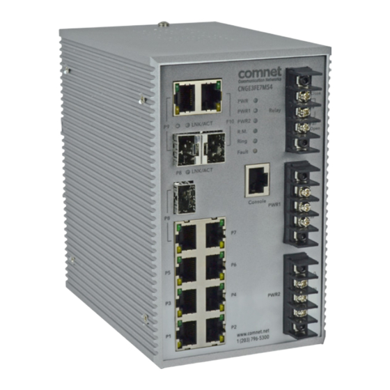
Page 13: Hardware Overview
INSTALLATION AND OPERATION MANUAL CNGE3FE7MS4 Hardware Overview Front Panel The following table describes the labels on the CNGE3FE7MS4. Port Description 10/100 RJ-45 fast 7 10/100BASE-T(X) RJ-45 fast Ethernet ports support auto- Ethernet ports negotiation. Default Setting : Speed: auto Duplex: auto... - Page 14 INSTALLATION AND OPERATION MANUAL CNGE3FE7MS4 CNGE3FE7MS4 1. 100Base FX/1000Base X combo ports 2. LNK/ACT LED for Gigabit LAN ports 3. LNK status LED for Ethernet LAN ports 4. Ethernet LAN ports 5. ACT status LED for LAN ports 6. Power LED 7.
-
Page 15: Front Panel Leds
INSTALLATION AND OPERATION MANUAL CNGE3FE7MS4 Front Panel LEDs Color Status Description Green AC/DC power ready Green AC/DC power module 1 activated. Green AC/DC power module 2 activated. Green C-Ring Master. Ring Green C-Ring enabled. Slowly blinking C-Ring topology has fault Fast blinking C-Ring works normally. -
Page 16: Wiring
INSTALLATION AND OPERATION MANUAL CNGE3FE7MS4 Wiring WARNING – Do not disconnect modules or wires unless power has been switched off or the area is known to be non-hazardous. The devices may only be connected to the supply voltage shown on the type plate. -
Page 17: Rear Panel
INSTALLATION AND OPERATION MANUAL CNGE3FE7MS4 Rear Panel The components in the rear of CNGE3FE7MS4 are shown as below: 1. Screw holes for wall mount kit. 2. DIN-Rail kit TECH SUPPORT: 1.888.678.9427 INS_CNGE3FE7MS4_REV– Rev. 4.30.14 PAGE 17... -
Page 18: Cables
Cables Ethernet Cables The CNGE3FE7MS4 switch has standard Ethernet ports. According to the link type, the switches use CAT 3, 4, 5, 5e UTP cables to connect to any other network device (PCs, servers, switches, routers, or hubs). Please refer to the following table for cable specifications. - Page 19 BI_DD- 1000 BASE-T RJ-45 Pin Assignments The CNGE3FE7MS4 switch will support auto MDI/MDI-X operation. You can use a straight-through cable to connect a PC to the switch. The table below shows the 10BASE-T/ 100BASE-TX MDI and MDI-X port pin outs.
-
Page 20: Sfp
Switch-B Console Port Cable CNGE3FE7MS4 switches can be managed by the console port. The DB-9 to RJ-45 cable can be found in the package. You can connect them to the PC via a RS-232 cable with DB-9 female connector and the other end (RJ-45 connector) connects to console port of switch. - Page 21 INSTALLATION AND OPERATION MANUAL CNGE3FE7MS4 DB9 Male DB9 Female Male Connector Female Connector Received Line Signal Detect (Received by DTE Received Line Signal Detect (Transmitted from Device) DCE Device) Received Data (Received by DTE Device) Transmitted Data (Transmitted from DCE Device)
-
Page 22: Web Management
INSTALLATION AND OPERATION MANUAL CNGE3FE7MS4 WEB Management Attention: While installing and upgrading firmware, please remove physical loop connection first. DO NOT power off equipment while the firmware is upgrading! Configuration by Web Browser This section details configuration through the Web browser. -
Page 23: Preparing For Web Management
INSTALLATION AND OPERATION MANUAL CNGE3FE7MS4 Preparing for Web Management The default value is as below: IP Address: 192.168.10.1 Subnet Mask: 255.255.255.0 Default Gateway: 192.168.10.254 User Name: admin Password: admin System Login 1. Launch Internet Explorer. 2. Type http://192.168.10.1 and the IP address of the switch. Press Enter. -
Page 24: Main Interface
INSTALLATION AND OPERATION MANUAL CNGE3FE7MS4 Main Interface Main interface System Information System Information interface System Information The system information will display the configuration of Basic Setting/Switch Setting page. Enable Location Alert Select Enable Location Alert and observe that the PWR1, PWR2 and FAULT LEDs of the switch will start to flash together. -
Page 25: Basic Setting
INSTALLATION AND OPERATION MANUAL CNGE3FE7MS4 Basic setting Switch Setting Switch setting interface Label Description System Name Assign the name of switch. The maximum length is 64 bytes System Description Display the description of switch. System Location Assign the switch physical location. The maximum length is 64 bytes... -
Page 26: Ip Setting
INSTALLATION AND OPERATION MANUAL CNGE3FE7MS4 IP Setting You can configure the IP Settings and DHCP client function through IP configuration. IP Configuration interface Label Description DHCP Client To enable or disable the DHCP client function. When DHCP client function is enabling, the switch will be assigned the IP address from the network DHCP server. -
Page 27: Time Setting
INSTALLATION AND OPERATION MANUAL CNGE3FE7MS4 Time Setting The SNTP (Simple Network Time Protocol) settings allow you to synchronize switch clocks from the Internet. SNTP Configuration interface Label Description SNTP Client Enable or disable SNTP function to get the time from the SNTP server. - Page 28 INSTALLATION AND OPERATION MANUAL CNGE3FE7MS4 Local Time Zone Conversion from UTC Time at 12:00 UTC November Time Zone - 1 hour 11 am Oscar Time Zone -2 hours 10 am ADT - Atlantic Daylight -3 hours 9 am AST - Atlantic Standard...
-
Page 29: Ptp Client
INSTALLATION AND OPERATION MANUAL CNGE3FE7MS4 PTP Client The Precision Time Protocol (PTP) is a time-transfer protocol defined in the IEEE 1588-2002 standard that allows precise synchronization of networks (e.g., Ethernet). Accuracy within the nanosecond range can be achieved with this protocol when using hardware-generated timestamps. -
Page 30: Auto Provision
INSTALLATION AND OPERATION MANUAL CNGE3FE7MS4 Auto Provision Auto Provision allows you to automatically update the switch firmware. You can put the firmware or configuration file on TFTP server. When you reboot the switch, it will upgrade automatically. Before updating, make sure you have your TFTP server ready and the firmware image and configuration file is on the TFTP server. -
Page 31: Backup & Restore
INSTALLATION AND OPERATION MANUAL CNGE3FE7MS4 Backup & Restore You can save current EEPROM value from the switch to TFTP server, then go to the TFTP restore configuration page to restore the EEPROM value. Backup & Restore interface Label Description TFTP Server IP Address Fill in the TFTP server IP Restore File Name Fill the file name. -
Page 32: Redundancy
INSTALLATION AND OPERATION MANUAL CNGE3FE7MS4 Redundancy DHCP Server DHCP Server – Setting The system provides with DHCP server function. Enable the DHCP server function and the switch system will be a DHCP server. DHCP Server Configuration interface Label Description DHCP Server Enable or Disable the DHCP Server function. -
Page 33: Dhcp Server - Client List
INSTALLATION AND OPERATION MANUAL CNGE3FE7MS4 DHCP Server – Client List When the DHCP server function is activated, the system will collect the DHCP client information and display in here. DHCP Server Client Entries interface DHCP Server – Port and IP bindings You can assign the specific IP address that is in the assigned dynamic IP range to the specific port. -
Page 34: Dhcp Server -Dhcp Relay Agent
INSTALLATION AND OPERATION MANUAL CNGE3FE7MS4 DHCP Server –DHCP Relay Agent The DHCP relay agent relays DHCP messages between clients and servers for DHCP on different subnet domains. DHCP relay agent use Option 82 to insert specific information into a request that is being forwarded to a DHCP server and, according to Option 82, to remove the specific information from a reply packet when forwarding server DHCP packets to a DHCP client. -
Page 35: Port Setting
INSTALLATION AND OPERATION MANUAL CNGE3FE7MS4 Port Setting Port Control Set the state, speed/duplex, flow control, and security of the port. Port Control interface Label Description Port No. Port number for setting. State Enable/Disable the port. Speed/Duplex Set Auto-negotiation, 100-full, 100-half, 10-full or 10-half mode. -
Page 36: Port Status
INSTALLATION AND OPERATION MANUAL CNGE3FE7MS4 Port Status The following information provides the current port status information. Port Status interface Rate Limit Limit the traffic of all ports, including broadcast, multicast and flooded unicast. You can also set Ingress or Egress to limit traffic received or transmitted bandwidth. -
Page 37: Port Trunk
INSTALLATION AND OPERATION MANUAL CNGE3FE7MS4 Port Trunk Port Trunk – Setting You can select static trunk or 802.3ad LACP to combine several physical links with a logical link to increase the bandwidth. Port Trunk - Setting interface Label Description Group ID Select port to join a trunk group. -
Page 38: Port Trunk - Status
INSTALLATION AND OPERATION MANUAL CNGE3FE7MS4 Port Trunk – Status Port Trunk - Status interface Label Description Group ID Trunk Group number Trunk Member Show Group port info C-Ring C-Ring is the most powerful Redundant Ring in the world. The recovery time is less than 10ms. - Page 39 RSTP mode. Apply Select Apply to set the configurations. Note: ComNet does not recommend setting one switch as a Ring Master and a Coupling Ring at the same time due to heavy load. TECH SUPPORT: 1.888.678.9427 INS_CNGE3FE7MS4_REV– Rev. 4.30.14 PAGE 39...
-
Page 40: Legacy Ring
CNGE3FE7MS4 Legacy Ring Legacy Ring interface Legacy ring provides support for the switch to be used in an existing ring of ComNet X-Ring enabled switches. X-Ring provides a faster redundant recovery than Spanning Tree topology. The action is similar to STP or RSTP, but the algorithms between them are not the same. In the X-Ring topology, every switch should be enabled with X-Ring or Legacy Ring function and two ports should be assigned as the member ports in the ring. -
Page 41: Com-Ring
INSTALLATION AND OPERATION MANUAL CNGE3FE7MS4 COM-Ring You can add ComNet switches into a network constructed by another ring technology and enable COM-Ring to cooperate with another vendor’s managed switch. ComRing interface Label Description Enable Enable the COM-Ring function Vendor Select the vendor whose ring you want to join... -
Page 42: C-Rstp
INSTALLATION AND OPERATION MANUAL CNGE3FE7MS4 C-RSTP C-RSTP is proprietary redundant ring technology invented by ComNet. Different from standard STP/RSTP, the recovery time of C-RSTP is <10ms and supports more nodes of connection in a ring topology. C-RSTP interface The application of C-RSTP is shown as below. -
Page 43: Rstp
INSTALLATION AND OPERATION MANUAL CNGE3FE7MS4 RSTP The Rapid Spanning Tree Protocol (RSTP) is an evolution of the Spanning Tree Protocol. It provides faster spanning tree convergence after a topology change. The system also supports STP and the system will auto detect the connected device that is running STP or RSTP protocol. - Page 44 INSTALLATION AND OPERATION MANUAL CNGE3FE7MS4 View the RSTP algorithm results at this table TECH SUPPORT: 1.888.678.9427 INS_CNGE3FE7MS4_REV– Rev. 4.30.14 PAGE 44...
- Page 45 INSTALLATION AND OPERATION MANUAL CNGE3FE7MS4 Label Description Path Cost (1-200000000) The cost of the path to the other bridge from this transmitting bridge at the specified port. Enter a number 1 through 200,000,000. Port Priority (0-240) Decide that port should be blocked by priority in LAN. Enter a numerical value that is a multiple of 16, 0 through 240.
-
Page 46: Mstp
INSTALLATION AND OPERATION MANUAL CNGE3FE7MS4 MSTP Multiple Spanning Tree Protocol (MSTP) is a standard protocol base on IEEE 802.1s. The function is that several VLANs can be mapped to a reduced number of spanning tree instances because most networks do not need more than a few logical topologies. It supports load- balancing schemes and the CPU is sparer than PVST (Cisco proprietary technology). - Page 47 INSTALLATION AND OPERATION MANUAL CNGE3FE7MS4 Label Description MSTP Enable Enable/disable MSTP function to configure the related parameters. Force Version The Force Version parameter can be used to force a VLAN Bridge that supports RSTP to operate in an STP-compatible manner.
- Page 48 INSTALLATION AND OPERATION MANUAL CNGE3FE7MS4 MSTP Port interface Label Description Port No. Select the port that you want to configure. Priority (0-240) Select which port should be blocked by priority in LAN. Enter a multiple of 16, 0 through 240.
- Page 49 INSTALLATION AND OPERATION MANUAL CNGE3FE7MS4 MSTP Instance interface Label Description Instance Set the instance from 1 to 15 State Enable or disable the instance VLANs Set that VLAN will belong that instance Proprietary (0-61440) A value used to identify the root bridge. The bridge with the lowest value has the highest priority and is selected as the root.
-
Page 50: Multicast
INSTALLATION AND OPERATION MANUAL CNGE3FE7MS4 Multicast IGMP Snooping Internet Group Management Protocol (IGMP) is used by IP hosts to register their dynamic multicast group membership. IGMP has 3 versions, IGMP v1, v2 and v3. Please refer to RFC 1112, 2236 and 3376. IGMP Snooping improves the performance of networks that carry multicast traffic. -
Page 51: Static Multicast Filtering
INSTALLATION AND OPERATION MANUAL CNGE3FE7MS4 Static Multicast Filtering Static multicast filtering is the system by that end stations only receive multicast traffic if they register to join specific multicast groups. With multicast filtering, network devices only forward multicast traffic to the ports that are connected to registered end stations. -
Page 52: Vlan
INSTALLATION AND OPERATION MANUAL CNGE3FE7MS4 VLAN A Virtual LAN (VLAN) is a logical network grouping that limits the broadcast domain that allows you to isolate network traffic. Only the members of the VLAN will receive traffic from the same members of VLAN. Basically, creating a VLAN from a switch is the logical equivalent of reconnecting a group of network devices to another Layer 2 switch. - Page 53 INSTALLATION AND OPERATION MANUAL CNGE3FE7MS4 Label Description VLAN Operation Mode Select VLAN Operation Mode: Disable, Port Base, 802.1Q GVRP Mode Enable/Disable GVRP function. Management VLAN ID Management VLAN can provide network administrator a secure VLAN to management Switch. Only the devices in the management VLAN can access the switch.
-
Page 54: Vlan Setting - Port Based
INSTALLATION AND OPERATION MANUAL CNGE3FE7MS4 VLAN Setting – Port Based Traffic is forwarded to the member ports of the same vlan group. vlan port based startup, set in the same group of the port, can be a normal transmission packet, without restricting the types of packets. - Page 55 INSTALLATION AND OPERATION MANUAL CNGE3FE7MS4 VLAN Configuration – Port Base interface-2 The following table describes the labels in this screen. Label Description Group Name VLAN name. VLAN ID Specify the VLAN ID Select port to join the VLAN group. Remove...
-
Page 56: Snmp
INSTALLATION AND OPERATION MANUAL CNGE3FE7MS4 SNMP Simple Network Management Protocol (SNMP) is the protocol developed to manage nodes (servers, workstations, routers, switches and hubs etc.) on an IP network. SNMP enables network administrators to manage network performance, find and solve network problems, and plan for network growth. -
Page 57: Snmpv3
INSTALLATION AND OPERATION MANUAL CNGE3FE7MS4 SNMPV3 Label Description Context Table Configure SNMP v3 context table. Assign the context name of context table. Select Apply to change context name User Table Configure SNMP v3 user table. User ID: set up the user name. -
Page 58: Snmp -Trap Setting
INSTALLATION AND OPERATION MANUAL CNGE3FE7MS4 SNMP –Trap Setting A trap manager is a management station that receives traps, the system alerts generated by the switch. If no trap manager is defined, no traps will be issued. Create a trap manager by entering the IP address of the station and a community string. -
Page 59: Traffic Prioritization
INSTALLATION AND OPERATION MANUAL CNGE3FE7MS4 Traffic Prioritization Traffic Prioritization includes 3 modes: port base, 802.1p/COS, and TOS/DSCP. By traffic prioritization function, you can classify the traffic into four classes for differential network application. IGS-3044GP(GC) series support 4 priority queues. QoS policy... -
Page 60: Port-Base Priority
INSTALLATION AND OPERATION MANUAL CNGE3FE7MS4 Port-base priority Port-based Priority interface Priority Assign Port with one of four available priority queues: High, Middle, Low, and Lowest. Apply Select Apply to set the configurations. Help Show help file. TECH SUPPORT: 1.888.678.9427 INS_CNGE3FE7MS4_REV– Rev. 4.30.14 PAGE 60... -
Page 61: Cos/802.1P
INSTALLATION AND OPERATION MANUAL CNGE3FE7MS4 COS/802.1p COS/802.1p interface COS/802.1p COS (Class Of Service) is also known as 802.1p. It describes that the output priority of a packet is determined by the user priority field in 802.1Q VLAN tag. The priority value is supported 0to7.COS value map to 4 priority queues: High, Middle, Low, and Lowest. -
Page 62: Tos/Dscp
INSTALLATION AND OPERATION MANUAL CNGE3FE7MS4 TOS/DSCP TOS/DSCP interface TOS/DSCP TOS (Type of Service) is a field in the IP header of a packet. This TOS field is also used by Differentiated Services and is called the Differentiated Services Code Point (DSCP). This field can determine the output priority of a packet and the priority value is supported 0to63. -
Page 63: Security
INSTALLATION AND OPERATION MANUAL CNGE3FE7MS4 Security Five useful functions can enhance security of switch: IP Security, Port Security, MAC Blacklist, and MAC address Aging and 802.1x protocol. Management Security Only IP in the Secure IP List can manage the switch through your defined management mode. -
Page 64: Static Mac Forwarding
INSTALLATION AND OPERATION MANUAL CNGE3FE7MS4 Static MAC Forwarding Static MAC Forwarding is to add static MAC addresses to hardware forwarding database. If port security is enabled at Port Control page, only the frames with MAC addresses in this list will be forwarded, otherwise will be discarded. -
Page 65: Mac Blacklist
INSTALLATION AND OPERATION MANUAL CNGE3FE7MS4 MAC Blacklist MAC Blacklist can eliminate the traffic forwarding to specific MAC addresses in list. Any frames forwarding to MAC addresses in this list will be discarded. Thus the target device will never receive any frame. -
Page 66: 802.1X - Radius Server
INSTALLATION AND OPERATION MANUAL CNGE3FE7MS4 802.1x 802.1x - Radius Server 802.1x makes the use of the physical access characteristics of IEEE802 LAN infrastructures in order to provide a authenticated and authorized devices attached to a LAN port. Please refer to IEEE 802.1X - Port Based Network Access Control. - Page 67 INSTALLATION AND OPERATION MANUAL CNGE3FE7MS4 Supplicant Timeout Set the period of time the switch waits for a supplicant response to an EAP request. Server Timeout Set the period of time the switch waits for a Radius server response to an authentication request.
-
Page 68: 802.1X-Port Authorized Mode
INSTALLATION AND OPERATION MANUAL CNGE3FE7MS4 802.1x-Port Authorized Mode Set the 802.1x authorized mode of each port. 802.1x Port Authorize interface Label Description Port Authorized Reject: force this port to be unauthorized. Mode Accept: force this port to be authorized. Authorize: the state of this port was determined by the outcome of the 802.1x authentication. -
Page 69: X-Port Authorized Mode
INSTALLATION AND OPERATION MANUAL CNGE3FE7MS4 802.1x-Port Authorized Mode Show 802.1x port authorized state. 802.1x Port Authorize State interface TACACS+ TECH SUPPORT: 1.888.678.9427 INS_CNGE3FE7MS4_REV– Rev. 4.30.14 PAGE 69... -
Page 70: Warning
INSTALLATION AND OPERATION MANUAL CNGE3FE7MS4 Warning Warning: function is very important for managing the switch. You can manage the switch by SYSLOG, E-MAIL, and Fault Relay. It helps monitor the switch status on remote site. When events occur, the warning message will be sent to your appointed server, E-MAIL, or relay fault to switch panel. - Page 71 INSTALLATION AND OPERATION MANUAL CNGE3FE7MS4 System Warning – SMTP Setting The SMTP is Short for Simple Mail Transfer Protocol. It is a protocol for e-mail transmission across the Internet. Please refer to RFC 821 - Simple Mail Transfer Protocol. System Warning – SMTP Setting interface...
- Page 72 INSTALLATION AND OPERATION MANUAL CNGE3FE7MS4 System Warning – Event Selection SYSLOG and SMTP are the two warning methods that supported by the system. Check the corresponding box to enable system event warning method you wish to choose. Please note that the checkbox cannot be checked when SYSLOG or SMTP is disabled.
-
Page 73: Monitor And Diag
INSTALLATION AND OPERATION MANUAL CNGE3FE7MS4 Monitor and Diag MAC Address Table Refer to IEEE 802.1 D Sections 7.9. The MAC Address Table, that is Filtering Database, supports queries by the Forwarding Process, as to whether a frame received by a given port with a given destination MAC address is to be forwarded through a given potential transmission port. -
Page 74: Port Overview
INSTALLATION AND OPERATION MANUAL CNGE3FE7MS4 Port Overview Port statistics show several statistics counters for all ports Port Overview interface Label Description Type Show port speed and media type. Link Show port link status. State Show ports enable or disable. TX GOOD Packet The number of good packets sent by this port. -
Page 75: Port Monitoring
INSTALLATION AND OPERATION MANUAL CNGE3FE7MS4 Port Monitoring Port monitoring function supports TX (egress) only, RX (ingress) only, and both TX/RX monitoring. TX monitoring sends any data that egress out checked TX source ports to a selected TX destination port as well. RX monitoring sends any data that ingress in checked RX source ports out to a selected RX destination port as well as sending the frame where it normally would have gone. -
Page 76: Sfp Monitor
INSTALLATION AND OPERATION MANUAL CNGE3FE7MS4 SFP Monitor DDM function, can pass SFP module which supports DDM function, measure the temperature of the apparatus and manage and set up event alarm module through DDM WEB System Event Log If system log client is enabled, the system event logs will be shown in this table. -
Page 77: Save Configuration
INSTALLATION AND OPERATION MANUAL CNGE3FE7MS4 Save Configuration If any configuration is changed, visit this screen and save current configuration data to the permanent flash memory. Otherwise, the current configuration will be lost when power is turned off or the system is reset. -
Page 78: Command Line Interface Management
CNGE3FE7MS4 Command Line Interface Management About CLI Management Besides WEB-base management, CNGE3FE7MS4 also supports CLI management. You can use console or telnet to management switch by CLI. CLI Management by RS-232 Serial Console (9600, 8, none, 1, none) Before Configuring by the RS-232 serial console, use an RJ45 to DB9-F cable to connect the Switch’s RS-232 Console port to your PCs’... - Page 79 INSTALLATION AND OPERATION MANUAL CNGE3FE7MS4 Step 2. Input a name for new connection Step 3. Select to use COM port number TECH SUPPORT: 1.888.678.9427 INS_CNGE3FE7MS4_REV– Rev. 4.30.14 PAGE 79...
- Page 80 INSTALLATION AND OPERATION MANUAL CNGE3FE7MS4 Step 4. The COM port properties setting, 9600 for Bits per second, 8 for Data bits, None for Parity, 1 for Stop bits and none for Flow control. Step 5. The Console login screen will appear. Use the keyboard to enter the Username and Password (same as for accessing via Web Browser), and then press Enter.
-
Page 81: Cli Management By Telnet
INSTALLATION AND OPERATION MANUAL CNGE3FE7MS4 CLI Management by Telnet. Users can use telnet to configure the switches. The default value is as below: IP Address: 192.168.10.1 Subnet Mask: 255.255.255.0 Default Gateway: 192.168.10.254 User Name: admin Password: admin Follow the steps below to access the console via Telnet. -
Page 82: Commands Level
INSTALLATION AND OPERATION MANUAL CNGE3FE7MS4 Commands Level Modes Access Method Prompt Exit Method About This Model User EXEC Begin a session switch> Enter logout or The user command available with your switch. quit. at the level of user is the subset of those available at the privileged level. -
Page 83: Symbol Of Command Level
INSTALLATION AND OPERATION MANUAL CNGE3FE7MS4 Symbol of Command Level. Mode Symbol of Command Level User EXEC Privileged EXEC Global configuration VLAN database Interface configuration I Commands Set List—System Commands Set Commands Level Description Example show config Show switch configuration switch>show config... - Page 84 INSTALLATION AND OPERATION MANUAL CNGE3FE7MS4 show admin Show administrator information switch#show admin dhcpserver enable Enable DHCP Server switch(config)#dhcpserver enable dhcpserver lowip Configure low IP address for IP switch(config)# dhcpserver lowip [Low IP] pool 192.168.1.1 dhcpserver highip Configure high IP address for IP...
-
Page 85: Commands Set List-Port Commands Set
INSTALLATION AND OPERATION MANUAL CNGE3FE7MS4 Commands Set List—Port Commands Set Commands Level Description Example interface fastEthernet Choose the port for modification. switch(config)#interface fastEthernet 2 [Portid] duplex Use the duplex configuration switch(config)#interface fastEthernet 2 [full | half] command to specify the duplex... - Page 86 INSTALLATION AND OPERATION MANUAL CNGE3FE7MS4 bandwidth out Set interface output bandwidth. switch(config)#interface fastEthernet 2 [Value] Rate Range is from 100 kbps to switch(config-if)#bandwidth out 100 102400 kbps or to 256000 kbps for giga ports, and zero means no limit. show bandwidth...
-
Page 87: Commands Set List-Trunk Command Set
INSTALLATION AND OPERATION MANUAL CNGE3FE7MS4 Commands Set List—Trunk command set Commands Level Description Example aggregator priority Set port group system priority switch(config)#aggregator priority 22 [1to65535] aggregator activityport Set activity port switch(config)#aggregator activityport [Port Numbers] aggregator group Assign a trunk group with LACP... -
Page 88: Commands Set List-Vlan Command Set
INSTALLATION AND OPERATION MANUAL CNGE3FE7MS4 Commands Set List—VLAN command set Commands Level Description Example vlan database Enter VLAN configure mode switch#vlan database vlan To set switch VLAN mode. switch(vlan)# vlanmode 802.1q [8021q | gvrp] switch(vlan)# vlanmode gvrp no vlan Disable vlan group (by VID) -
Page 89: Commands Set List-Spanning Tree Command Set
INSTALLATION AND OPERATION MANUAL CNGE3FE7MS4 Commands Set List—Spanning Tree command set Commands Level Description Example spanning-tree enable Enable spanning tree switch(config)#spanning-tree enable spanning-tree priority Configure spanning tree priority switch(config)#spanning-tree priority [0to61440] parameter 32767 spanning-tree max-age Use the spanning-tree max-age switch(config)# spanning-tree max-age... -
Page 90: Commands Set List-Qos Command Set
INSTALLATION AND OPERATION MANUAL CNGE3FE7MS4 stp-admin-p2p Admin P2P of STP priority on this switch(config)#interface fastEthernet 2 [Auto|True|False] interface. switch(config-if)# stp-admin-p2p Auto stp-admin-edge Admin Edge of STP priority on this switch(config)#interface fastEthernet 2 [True|False] interface. switch(config-if)# stp-admin-edge True stp-admin-non-stp Admin NonSTP of STP priority on... -
Page 91: Commands Set List-Igmp Command Set
INSTALLATION AND OPERATION MANUAL CNGE3FE7MS4 Commands Set List—IGMP command set Commands Level Description Example igmp enable Enable IGMP snooping function switch(config)#igmp enable Igmp-query auto Set IGMP query to auto mode switch(config)#Igmp-query auto Igmp-query force Set IGMP query to force mode... -
Page 92: Commands Set List-Mac/Filter Table Command Set
INSTALLATION AND OPERATION MANUAL CNGE3FE7MS4 Commands Set List—MAC/Filter Table command set Commands Level Description Example mac-address-table static Configure MAC address table of switch(config)#interface fastEthernet 2 hwaddr interface (static). switch(config-if)#mac-address-table [MAC] static hwaddr 000012345678 mac-address-table filter Configure MAC address switch(config)#mac-address-table filter... -
Page 93: Commands Set List-Snmp Command Set
INSTALLATION AND OPERATION MANUAL CNGE3FE7MS4 Commands Set List—SNMP command set Commands Level Description Example snmp agent-mode Select the agent mode of SNMP switch(config)#snmp agent-mode [v1v2c | v3] v1v2c snmp-server host Configure SNMP server host switch(config)#snmp-server host [IP address] information and community string 192.168.10.50 community public trap-... -
Page 94: Commands Set List-Port Mirroring Command Set
INSTALLATION AND OPERATION MANUAL CNGE3FE7MS4 Commands Set List—Port Mirroring command set Commands Level Description Example monitor rx Set RX destination port of monitor switch(config)#monitor rx function monitor tx Set TX destination port of monitor switch(config)#monitor tx function show monitor Show port monitor information... -
Page 95: Commands Set List-802.1X Command Set
INSTALLATION AND OPERATION MANUAL CNGE3FE7MS4 Commands Set List—802.1x command set Commands Level Description Example 8021x enable Use the 802.1x global switch(config)# 8021x enable configuration command to enable 802.1x protocols. 8021x system radiousip Use the 802.1x system radious IP switch(config)# 8021x system radiousip... -
Page 96: Commands Set List-Tftp Command Set
INSTALLATION AND OPERATION MANUAL CNGE3FE7MS4 8021x portstate Use the 802.1x port state interface switch(config)#interface fastethernet 3 [disable | reject | accept | configuration command to set the switch(config-if)#8021x portstate authorize] state of the selected port. accept show 8021x Display a summary of the 802.1x switch>show 8021x... - Page 97 INSTALLATION AND OPERATION MANUAL CNGE3FE7MS4 smtp password Configure authentication switch(config)#smtp password [password] password smtp rcptemail Configure Rcpt e-mail Address switch(config)#smtp rcptemail 1 Alert@ [Index] [Email address] test.com show smtp Show the information of SMTP switch#show smtp no smtp Disable SMTP function...
-
Page 98: Commands Set List-Sntp Command Set
INSTALLATION AND OPERATION MANUAL CNGE3FE7MS4 Commands Set List—SNTP command set Commands Level Description Example sntp enable Enable SNTP function switch(config)#sntp enable sntp daylight Enable daylight saving time, if switch(config)#sntp daylight SNTP function is inactive, this command can’t be applied. sntp daylight-period... -
Page 99: Commands Set List - C-Ring Command Set
INSTALLATION AND OPERATION MANUAL CNGE3FE7MS4 Commands Set List — C-Ring command set Commands Level Description Example Ring enable Enable C-Ring switch(config)# ring enable Ring master Enable ring master switch(config)# ring master Ring couplering Enable couple ring switch(config)# ring couplering Ring dualhoming... -
Page 100: Technical Specifications
INSTALLATION AND OPERATION MANUAL CNGE3FE7MS4 Technical Specifications Physical Ports 10/100 BASE-T(X) Ports 7 RJ45, Auto MDI/MDIX Gigabit Combo Ports 3 with 10/100/1000BASE-T(X) and 100/1000BASE-X SFP port Technology Ethernet Standards IEEE 802.3 for 10BASE-T IEEE 802.3u for 100BASE-TX and 100BASE-FX IEEE 802.3z for 1000BASE-X IEEE 802.3ab for 1000BASE-T... - Page 101 INSTALLATION AND OPERATION MANUAL CNGE3FE7MS4 Network Redundancy ComRing C-Ring Legacy Ring C-RSTP RSTP MSTP Warning / Monitoring Relay output for fault event alarming System Syslog server / client to record and view events Include SMTP for event warning notification via email Event selection support RS232 Serial Console Port RS232 in RJ-45 connector with console cable.
- Page 102 INSTALLATION AND OPERATION MANUAL CNGE3FE7MS4 Regulatory approvals FCC Part 15, CISPR (EN55022) class A , EN50155 (EN50121-3-2, EN55011, EN50121-4) EN61000-4-2 (ESD) EN61000-4-3 (RS) EN61000-4-4 (EFT) EN61000-4-5 (Surge) EN61000-4-6 (CS) EN61000-4-8 EN61000-4-11 Shock IEC60068-2-27 Free Fall IEC60068-2-32 Vibration IEC60068-2-6 Safety EN60950-1...
- Page 103 INSTALLATION AND OPERATION MANUAL CNGE3FE7MS4 TECH SUPPORT: 1.888.678.9427 INS_CNGE3FE7MS4_REV– Rev. 4.30.14 PAGE 103...
- Page 104 8 TURNBERRY PARK ROAD | GILDERSOME | MORLEY | LEEDS, UK LS27 7LE T: +44 (0)113 307 6400 | F: +44 (0)113 253 7462 | INFO-EUROPE@COMNET.NET © 2014 Communications Networks Corporation. All Rights Reserved. “ComNet” and the “ComNet Logo” are registered trademarks of Communication Networks, LLC.
Need help?
Do you have a question about the CNGE3FE7MS4 and is the answer not in the manual?
Questions and answers