Table of Contents
Advertisement
Quick Links
INSTALLATION AND OPERATION MANUAL
CWFE8MS/DIN
INDUSTRIAL GRADE MANAGED
ETHERNET SWITCH WITH (8) 10/100TX PORTS
V2.0 – March 2011
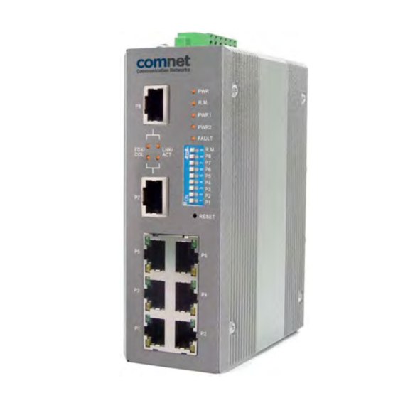
The ComNet CWFE8MS/DIN Managed Ethernet Switch provides transmission of 10/100 BASE-T Ethernet data.
These units are available for use with conventional CAT-5e copper transmission media. Up to 8 electrical ports
are available for easily implementing point-to-point, linear add-drop, drop-and-repeat, star or true self-healing
ring and mesh network system architectures. The electrical ports support the 10/100 Mbps (10/100 BASE-TX)
Ethernet IEEE 802.3 protocol. Auto-negotiating and auto- MDI/MDIX features are provided for simplicity and ease
of installation. Plug-and-play design ensures ease of installation, and no electrical or optical adjustments are ever
required. The CWFE8MS/DIN incorporates LED indicators for monitoring the operating status of the managed
switch and network.
Advertisement
Table of Contents

Related Manuals for Comnet CWFE8MS/DIN


Summary of Contents for Comnet CWFE8MS/DIN
- Page 1 Ethernet IEEE 802.3 protocol. Auto-negotiating and auto- MDI/MDIX features are provided for simplicity and ease of installation. Plug-and-play design ensures ease of installation, and no electrical or optical adjustments are ever required. The CWFE8MS/DIN incorporates LED indicators for monitoring the operating status of the managed switch and network.
- Page 2 FCC Warning This Equipment has been tested and found to comply with the limits for a Class-A digital device, pursuant to Part 15 of the FCC rules. These limits are designed to provide reasonable protection against harmful interference in a residential installation. This equipment generates, uses, and can radiate radio frequency energy.
-
Page 3: Table Of Contents
Content Chapter 1 Introduction..............1 1.1 Hardware Features ............1 1.2 Software Features .............3 1.3 Package Contents .............6 Chapter 2 Hardware Description..........7 2.1 Physical Dimensions............7 2.2 Front Panel ................7 2.3 Bottom View...............8 2.4 DIP-switch................9 2.5 LED Indicators ..............10 Chapter 3 Hardware Installation ..........11 3.1 Installation Steps .............11 3.2 DIN-Rail Mounting ............12 3.3 Wall Mount Plate Mounting..........14... - Page 4 3.6 Wiring the Fault Alarm Contact........16 Chapter 4 Network Application ..........17 4.1 X-Ring Application ............18 4.2 Coupling Ring Application..........19 4.3 Dual Homing Application ..........20 Chapter 5 Web-Based Management ........21 5.1 About Web-based Management ........21 5.2 Preparing for Web Management........22 5.3 System Login ..............22 5.4 System Information............24 5.5 Port status................25 5.5.1 Single Port Information .............
- Page 5 5.10 Alert ................39 5.10.1 Email Alert Configuration............39 5.10.2 Event Configuration ..............40 5.10.3 Power Alarm Configuration............. 42 5.11 IP Configuration .............42 5.12 SNTP Configuration............43 5.13 IP Security ..............44 5.14 RSTP Configuration............46 5.14.1 System Configuration ............. 46 5.14.2 Per Port Configuration ............48 5.15 X-Ring................49 5.16 QoS Configuration ............51 5.17 IGMP................54...
- Page 6 5.20.1 TFTP Restore Configuration........... 58 5.20.2 TFTP Backup Configuration ........... 58 5.21 TFTP Update Firmware ..........59 5.22 Factory Default ..............60 5.23 Save Configuration ............60 5.24 System Reboot ..............61 5.25 Rate Control..............61 5.26 System Log..............62 5.26.1 System Log Configuration ............62 5.26.2 Event Configuration ..............
-
Page 7: Chapter 1 Introduction
Chapter 1 Introduction The CWFE8MS/DIN managed Ethernet switch is a cost-effective solution and meets the high reliability requirements demanded by commercial applications. The CWFE8MS/DIN managed Ethernet switch can be easily managed through the Web GUI. It also provides the X-Ring function that can prevent network connection failures. - Page 8 Back-plane 1.6 Gbps Packet throughput 2.38Mpps @64bytes (8TX) ability Per port: Link/Activity (Green), Full duplex/Collision (Yellow) Per unit: Power (Green) Power 1 (Green) Power 2 (Green) Fault (Yellow) Master (Green) 10Base-T: 2-pair UTP/STP Cat. 3, 4, 5 cable EIA/TIA-568 100-ohm (100m) Network Cable 100Base-TX: 2-pair UTP/STP Cat.
-
Page 9: Software Features
Operation Humidity 5% to 95% (Non-condensing) Storage to 85 Temperature Case Dimension IP-30, 54 mm (W) x 135 mm (H) x 105mm (D) FCC Class A, CE EN61000-4-2 (ESD), CE EN61000-4-3 (RS), CE EN-61000-4-4 (EFT), CE EN61000-4-5 (Surge), CE EN61000-4-6 (CS), CE EN61000-4-8, CE EN61000-4-11, CE EN61000-4-12, CE EN61000-6-2, CE EN61000-6-4 Safety... - Page 10 RFC 1213 MIBII RFC 1493 Bridge MIB RMON RFC 1757 RFC 2674 VLAN MIB SNMP MIB RFC 1643 Ethernet like MIB RFC1215 Trap MIB IGMP MIB. Private MIB for switch information, X-Ring, port alarm, TFTP firmware upgrade, reset, port mirror, IP security Up to 3 Trap stations Cold start, Port link Up, Port link down, Authentication Failure SNMP Trap...
- Page 11 IEEE802.1d spanning tree Spanning tree IEEE802.1w rapid spanning tree IGMP v1 and Query mode IGMP Up to 256 groups SNTP Simple network time protocol SMTP Simple mail transfer protocol System Event Log Support system log record and remote system log server Management IP IP address security to prevents unauthorized intruder security...
-
Page 12: Package Contents
CWFE8MS/DIN managed Ethernet switch One DIN-Rail (attached on the switch) One wall mount plate and six screws User manual CD Compare the contents of your switch with the standard checklist above. If any item is damaged or missing, please contact ComNet Customer-Care. -
Page 13: Chapter 2 Hardware Description
This section introduces the switch hardware spec, port, cabling information, and wiring installation. 2.1 Physical Dimensions The CWFE8MS/DIN managed Ethernet switch dimensions are: (W x H x D) is 54mm x 135mm x 105mm 2.2 Front Panel The front panel of the CWFE8MS/DIN managed Ethernet switch is shown below. -
Page 14: Bottom View
2.3 Bottom View The bottom panel of the CWFE8MS/DIN managed Ethernet switch consists of one terminal block connector within two DC power inputs and one DC IN power jack. -
Page 15: Dip-Switch
2.4 DIP-switch The switch provides 9 DIP-switches for configuring the relay alarm operational mode and the ring master operational mode. The default value of Dipswitch is OFF. Stat DIP Switch No Description Disable port 1 Alarm Enable port 1 Alarm. If the port’s link fails, the fault LED will light up. Disable port2 Alarm Enable port 2 Alarm. -
Page 16: Led Indicators
2.5 LED Indicators There are 7 diagnostic LEDs located on the front panel of the commercial switch. They display real-time information about the system and operational status. The following table provides a description of the status LEDs and their meaning for the switch. Status Meaning Green... -
Page 17: Chapter 3 Hardware Installation
Chapter 3 Hardware Installation This section describes how to install the CWFE8MS/DIN managed Ethernet switch and the installation points attached. 3.1 Installation Steps 1. Unpack the commercial switch 2. Check the DIN-Rail mounting bracket is on the switch. If the DIN-Rail is not attached, please refer to the DIN-Rail Mounting section for DIN-Rail installation. -
Page 18: Din-Rail Mounting
3.2 DIN-Rail Mounting The DIN-Rail is attached to the switch when it leaves factory. If the DIN-Rail is not attached to the commercial switch, please see the following illustration to attach the DIN-Rail on the switch. Follow the steps below to install the industrial switch. Rear Panel of the switch Use the screws to screw the DIN-Rail on the industrial switch... - Page 19 Insert the top of DIN-Rail into the track. Lightly push the DIN-Rail into the track. Check that the DIN-Rail is secured to the track. To remove the switch from the track, reverse above steps.
-
Page 20: Wall Mount Plate Mounting
3.3 Wall Mount Plate Mounting Follow the steps below to mount the switch with a wall mount plate. 1. Remove the DIN-Rail from the industrial switch; loosen the screws and remove the DIN-Rail. 2. Place the wall-mount plate on the rear panel of the commercial switch. 3. -
Page 21: Cabling
3.4 Cabling Use eight twisted-pair, Category 5 cables for the RJ-45 port connection. The cable between the converter and the link partner (switch, hub, workstation, etc.) must be less than 100 meters (328 ft.) long. 3.5 Wiring the Power Inputs Please follow below steps to insert the power wire. -
Page 22: Wiring The Fault Alarm Contact
3.6 Wiring the Fault Alarm Contact The fault-alarm contact is in the middle of the terminal-block connector as the figure shows below. By inserting the wires and setting the DIP switches to “ON” status, it will detect the fault status of power and port link failures. The following figure shows an application example for the fault alarm contact. -
Page 23: Chapter 4 Network Application
Chapter 4 Network Application This chapter provides sample applications to help the user to have a better idea of actual switch function applications. A sample application of the switch is seen below:... -
Page 24: X-Ring Application
4.1 X-Ring Application The CWFE8MS/DIN switch supports the X-Ring protocol that can allow your network system to recover from a network connection failure within 300ms or less, making your network system more reliable. The X-Ring algorithm is similar to the spanning tree protocol (STP) algorithm but it has a faster recovery time than STP. -
Page 25: Coupling Ring Application
4.2 Coupling Ring Application Within the network there maybe more than one X-Ring group. By using the coupling ring function more than one X-Ring can be connect for redundant backup. This can ensure the transmission between the two ring groups will not fail. A sample of the coupling ring application figure is shown below:... -
Page 26: Dual Homing Application
4.3 Dual Homing Application The Dual Homing function is designed to prevent a lost connection between the X-Ring group and upper level/core switch. The Dual Homing function only works when the X-Ring function is active. The maximum allowable Dual Homing port is set at one in a X-Ring group. -
Page 27: Chapter 5 Web-Based Management
Chapter 5 Web-Based Management This section introduces the configuration and functions of the Web-Based management. The following configuration steps are based on the firmware version 1.06. 5.1 About Web-based Management On the CPU board of the switch there is an embedded HTML web site residing in the flash memory, which offers advanced management features and allows users to manage the switch from anywhere on the network through a standard browser such as Microsoft Internet Explorer. -
Page 28: Preparing For Web Management
5.2 Preparing for Web Management Before using web management, install the switch on the network and make sure that any one of PCs on your network can connect to the switch through the web browser. The switch default settings for the IP Address, subnet mask, username and password are identified below: IP Address: 192.168.10.1 Subnet Mask: 255.255.255.0... - Page 29 Login Screen...
-
Page 30: System Information
5.4 System Information System Description: Display the description of switch. Read only cannot be modified. Firmware Version: Display the switch’s firmware version. Kernel Version: Display the kernel software version. Hardware version: Display the switch hardware version. MAC Address: Display the unique hardware address assigned by manufacturer (default) Switch settings interface [NOTE] Remember to use “Save Configuration”, otherwise the new configuration will be... -
Page 31: Port Status
5.5 Port status Display every port’s status depending on user’s setting and the negotiation result. Port: the port’s number Type: the speed mode, ex: 100TX = 100Mbps Link: Down means No Link. UP is for Link State: Displays port status as disabled or enabled. Unlink will be treated as off Negotiation: Displays the auto negotiation mode: auto/force. -
Page 32: Single Port Information
5.5.1 Single Port Information Selecting the port on the panel figure on the left side of web page, the user will see the single port information window callout as below figure shows. Port information interface... -
Page 33: Port Statistics
5.6 Port Statistics Display the current port statistic information. Select to clean all counts. Port Statistics Interface 5.7 Port Control Modifying the port status Select the port by scrolling the Port column State: disable or enable control of this port Negotiation: set auto negotiation mode as Auto, Nway (specify the speed/duplex on this port and enable auto-negotiation), or Force Speed: Set the speed of the port... -
Page 34: Port Mirroring
Duplex mode. The default value is Disable 7. Click button to apply configuration 8. The port’s current configuration is display in column below when the port is selected [NOTE] Remember to use “Save Configuration”, otherwise the new configuration will be lost when the switch is powered off. - Page 35 Monitor Port: the ports that the user wants to monitor. All monitor port traffic will be copied to the mirror port. A maximum of 7 monitor ports can be selected in one switch. The user can choose the port to be monitored in one mirror mode. [NOTE] If you want to disable the function, select the monitor mode as disabled.
-
Page 36: Vlan Configuration
5.9 VLAN configuration A Virtual LAN (VLAN) is a logical network grouping that limits the broadcast domain that would allow you to isolate network traffic so only the members of the VLAN will receive traffic from the same members of VLAN. Basically, creating a VLAN from a switch is logically equivalent of reconnecting a group of network devices to another Layer 2 switch. -
Page 37: Port-Based Vlan
5.9.1 Port-based VLAN Packets can go among only members of the same VLAN group. All unselected ports are treated as belonging to another single VLAN. If the port-based VLAN is enabled, the VLAN-tagging is ignored. In order for an end station to send packets to different VLANs, it has to be either capable of tagging packets it sends with VLAN tags or attached to a VLAN-aware bridge that is capable of classifying and tagging the packet with a different VLAN ID, based on not only default PVID but also other information about the packet, such as the protocol. - Page 38 Select to add a new VLAN group. The maximum number of VLAN groups is 64. Enter the VLAN name, group ID and group the members of VLAN group Click VLAN—PortBase Add interface The VLAN group list will display right after. Select Next Page to view other VLAN groups.
- Page 39 button to delete unwanted VLAN groups. button to modify an existing VLAN group. Remember to use “Save Configuration”, otherwise the new configuration will be lost when the switch is powered off.
-
Page 40: 802.1Q Vlan
5.9.2 802.1Q VLAN Tagged-based VLAN is an IEEE 802.1Q specification standard. It is possible to create a VLAN across devices from different switch venders. IEEE 802.1Q VLAN uses a technique to insert a “Tag” into the Ethernet frames. The Tag contains a VLAN Identifier (VID) that indicates the VLAN numbers. - Page 41 Basic Select button Management VLAN ID: this is used for Remote Management Security. It includes remote management that includes telnet, SNMP, and Web browse the switch when the port of the VLAN group ID is equal to the Management VLAN ID. Enter the specific VLAN ID number in Management VLAN ID column and select the check box, and select the button to enable the function.
- Page 42 802.1q VLAN –Add interface Select Next, and then the page will display as shown below:...
- Page 43 Set the outgoing frames that are VLAN-Tagged frames or untagged, and then select Tag: outgoing frames with VLAN-Tagged Untag: outgoing frames without VLAN-Tagged Port VID: Configure port VID settings Port VLAN ID: Enter the port VLAN ID Select To reset to default value, click Default button...
- Page 44 802.1q VLAN – Port VLAN ID interface Remember to use “Save Configuration”, otherwise the new configuration will be lost when the switch is powered off.
-
Page 45: Alert
5.10 Alert There are three kinds of alerts – e-mail, event, and power alarm. You can configure each alert function, as required. 5.10.1 Email Alert Configuration When the specific events occur, the system will send the alert to the email account that is assigned by user. -
Page 46: Event Configuration
Email Alert Configuration interface 5.10.2 Event Configuration The selected events that occur will send out the alert to the assigned SMTP server and also can set up port events for alerting. System event selection: 4 selections – device cold start, Power status, SNMP Authentication Failure, and X-Ring topology changes. - Page 47 Port event selection: Select the per port events. Per port has 3 selections – Link UP, Link Down, and Link UP & Link Down. Disable means no event is selected. Link UP: the system will send out an alert when a port connection is up only. Link Down: the system will send out an alert message when the port connection is down only.
-
Page 48: Power Alarm Configuration
5.10.3 Power Alarm Configuration Power alarm function enables the Relay alarm action. Without enabling the power alarm function, the Relay alarm action will not work even if the Relay alarm is set. Mark the check box and select button. Power Alarm interface 5.11 IP Configuration Configure the IP Settings and DHCP client function, and then select to apply... -
Page 49: Sntp Configuration
the network DHCP server will assign the IP address for the switch and display it in this column. The default IP Address is 192.168.16.1. Subnet Mask: Assign the subnet mask of the IP address. If DHCP client function is enabled the user does not need to assign the subnet mask. Gateway: Assign the network gateway for the CWFE8MS-DIN switch. -
Page 50: Ip Security
Daylight Saving Offset (mins): Configure the offset value Synchronization Interval (secs): The Synchronization Interval is used for sending synchronizing packets periodically. User can assign range from 64s to 1024s. The default setting of these values is “0”. This means that you disable the auto synchronization feature in SNTP client mode. - Page 51 Enable the IP Security: mark the check box to enable the IP security function. Security IP 1 ~ 10: user can assign up to 10 specific IP address. Only these 10 IP address can access and manage the switch through the Web browser. Select button to apply the configuration Remember to use “Save Configuration”, otherwise the new configuration will be lost...
-
Page 52: Rstp Configuration
5.14 RSTP Configuration The Rapid Spanning Tree Protocol (RSTP) is an evolution of the Spanning Tree Protocol and provides for faster spanning tree convergence after a topology change. The system also supports STP and the system will auto-detect the connected device that is running STP or RSTP protocol. - Page 53 [NOTE] Must follow the rule to configure the MAX Age, Hello Time, and Forward Delay Time. 2 x (Forward Delay Time value –1) > = Max Age value >= 2 x (Hello Time value +1) Remember to use “Save Configuration”, otherwise the new configuration will be lost when the switch is powered off.
-
Page 54: Per Port Configuration
5.14.2 Per Port Configuration Configuring the path cost and priority of every port 1. Select the port in Port column 2. Path Cost: The cost of the path to the other bridge from this transmitting bridge at the specified port. Enter a number 1 through 200000000. 3. -
Page 55: X-Ring
RSTP – Per Port Configuration interface 5.15 X-Ring X-Ring provides a faster redundant recovery than Spanning Tree topology. The action is similar with STP or RSTP, but the algorithms are not the same. In the X-Ring topology, every switch should enable the X-Ring function and assign two member ports in the ring. - Page 56 backup port will automatically become a working port to recover from the failure. The switch supports one Dipswitch for configuring the switch as the ring master or slave mode. The ring master has the rights to negotiate and place the command to other switches in the X-Ring group.
-
Page 57: Qos Configuration
X-Ring Interface [NOTE] 1. When the X-Ring function is enabled, RSTP has to be disabled. The X-Ring function and RSTP function cannot be active at the same time. 2. Remember to use “Save Configuration”, otherwise the new configuration will be lost when the switch is powered off. - Page 58 Port-base: the port priority will follow the default port priority that the user has assigned – High, middle, low, or lowest COS only: the port priority will only follow the COS priority that the user has assigned TOS only: the port priority will only follow the TOS priority that the user has assigned COS first: the port priority will follow the COS priority first, and then other priority rule...
- Page 59 QoS configuration Interface...
-
Page 60: Igmp
5.17 IGMP The Internet Group Management Protocol (IGMP) is an internal protocol of the Internet Protocol (IP) suite. IP manages multicast traffic by using switches, routers, and hosts that support IGMP. Enabling IGMP allows the ports to detect IGMP queries and report packets and manage IP multicast traffic through the switch. -
Page 61: Security Manager
IGMP Snooping interface 5.18 Security Manager Changing the web management login user name and password for the management security issue User name: Enter in the new user name (The default is “admin”) Password: Enter in the new password (The default is “admin”) Confirm password: Re-enter the new password And then, select Security Manager interface... -
Page 62: Snmp Configuration
5.19 SNMP Configuration The SNMP is a Protocol that governs the transfer of information between management and agent. The switch supports SNMP V1. Define management stations as trap managers and to enter SNMP community strings. Also, define a name, location, and contact person for the switch. Fill in the system options data, and then click to update the changes. -
Page 63: Trap Manager
5.19.3 Trap Manager A trap manager is a management station that receives traps that are the system alerts generated by the switch. If no trap manager is defined, no traps will be issued Create a trap manager by entering the IP address of the station and a community string. IP Address: Enter in the trap device IP Community Strings: the trap device community strings Trap version: the trap has two versions –... -
Page 64: Configuration Backup
Saving the current flash ROM value from the switch to the TFTP server, go to the TFTP restore configuration page to restore the image value back to the CWFE8MS/DIN switch. TFTP Server IP Address: Enter the TFTP server IP Address... -
Page 65: Tftp Update Firmware
Backup File Name: Enter the file name Select TFTP Backup Configuration interface 5.21 TFTP Update Firmware Updating the switch’s firmware. Before updating, make sure the TFTP server is ready and the firmware image resides on the TFTP server. TFTP Server IP Address: Enter in the TFTP server IP address Firmware File Name: the name of firmware image Select TFTP Update Firmware interface... -
Page 66: Factory Default
5.22 Factory Default Resetting the switch to the default configuration. The IP address, subnet mask, default gateway, username, and password will remain as the user had configured it. Select Default button to reset the switch to the default setting. Factory Default interface 5.23 Save Configuration Saving the switch configuration to the flash memory. -
Page 67: System Reboot
5.24 System Reboot Reboot the switch in software reset. Select button to reboot the switch. System Reboot interface 5.25 Rate Control Set up every port’s bandwidth rate and packet limitation type. Limit Packet type: select the packet type that needs to be filtered. The packet types have all types of packets, broadcast/multicast/unknown uni-cast packet, broadcast/multicast packet,... -
Page 68: System Log
[NOTE] 1. Remember to execute the “Save Configuration”, otherwise the new configuration will be lost when the switch is powered off. 2. QoS and Rate control cannot be existed at the same. Rate Control Interface 5.26 System Log Set up system log events and view the system log events. 5.26.1 System Log Configuration View the system log events. - Page 69 System Log Client Mode: Select in Client Only, Server Only, or Both mode System Log Server IP: Assign the system log server IP address Select button to apply the configuration System Log Configuration interface...
-
Page 70: Event Configuration
5.26.2 Event Configuration Select the system log events. When selected events occur, the system will send out the log information. Also, per port log events can be selected. System event selection: 4 selections – device cold start, power status, SNMP Authentication Failure, and X-Ring topology change. - Page 71 Event Configuration interface...
-
Page 72: Trouble Shooting
Check for loose power connections, power losses or surges at the power outlet. If you still cannot resolve the problem, contact the ComNet for assistance. If the CWFE8MS-DIN LED indicators are normal and the connected cables are correct but the packets still cannot be transmitted, please check the system’s... -
Page 73: Appendix A-Rj45 Pin Assignment
Appendix A-RJ45 Pin Assignment RJ-45 ports There are 8x 10/100Mbps auto-sensing electrical ports for 10Base-T or 100Base-TX devices connection. The UTP ports will auto-sense for either 10Base-T or 100Base-TX connections. Auto MDI/MDIX means that another switch or workstation may be connected without changing straight through or crossover cabling. - Page 74 Pin MDI-X Signal Name MDI Signal Name Receive Data plus (RD+) Transmit Data plus (TD+) Receive Data minus (RD-) Transmit Data minus (TD-) Transmit Data plus (TD+) Receive Data plus (RD+) Transmit Data minus (TD-) Receive Data minus (RD-) Straight Through Cable Schematic Cross Over Cable Schematic...
- Page 75 Technical Support The ComNet Technical Support and Design Center provides technical pre-sale and post-sale support for Ethernet transmission network and fiber optic system design and assistance for when you require one-on-one help from an expert. Our Technical Support department is staffed by some of the most highly experienced, regarded and recognized experts in the industry.
Need help?
Do you have a question about the CWFE8MS/DIN and is the answer not in the manual?
Questions and answers