
Related Manuals for Mitsubishi Electric Q80BD-J71GP21-SX


Summary of Contents for Mitsubishi Electric Q80BD-J71GP21-SX
- Page 1 CC-Link IE Controller Network Interface Board User's Manual (For SW1DNC-MNETG-B) -Q80BD-J71GP21-SX -Q80BD-J71GP21S-SX -Q81BD-J71GP21-SX -Q81BD-J71GP21S-SX...
-
Page 3: Safety Precautions
SAFETY PRECAUTIONS (Be sure to read these instructions before using the product.) Before using this product, read this manual and the relevant manuals introduced in this manual carefully and handle the product correctly with full attention to safety. Note that these precautions apply only to this product. Refer to the user's manual of your CPU module for safety precautions on programmable controller systems. -
Page 4: Installation Precautions
[Design Precautions] WARNING Configure safety circuits external to the programmable controller to ensure that the entire system operates safely even when a fault occurs in a personal computer. Failure to do so may result in an accident due to an incorrect output or malfunction. (1) Emergency stop circuits, protection circuits, and protective interlock circuits for conflicting operations (such as forward/reverse rotations or upper/lower limit positioning) must be configured external to the programmable controller. - Page 5 CAUTION Use the board in an environment that meets the general specifications in this manual. Failure to do so may result in electric shock, fire, malfunction, or damage to or deterioration of the product. Do not directly touch any conductive parts and electronic components of the board. Doing so may cause malfunction or failure of the board.
-
Page 6: Wiring Precautions
[Wiring Precautions] WARNING Shut off the external power supply for the system in all phases before installing the board or starting wiring. Failure to do so may result in electric shock, damage to the product, or malfunction. After installation of the board and wiring, attach the cover on the module before turning it on for operation. - Page 7 [Wiring Precautions] CAUTION Use a specified tool for crimping of the cable and contacting pin. Imperfect crimping may cause a malfunction. Verify the pin-out and fully insert the crimped contacting pin into the connector. Imperfect insertion may cause a failure or malfunction. Insert the wired external power supply cable into the external power supply cable connector until a click is heard.
- Page 8 [Startup/Maintenance Precautions] CAUTION Thoroughly read the manual and ensure the safety before performing program modification during operation, forced output, operation such as RUN, STOP and PAUSE. An improper operation will result in mechanical damage or accidents. Do not disassemble or modify the board. Doing so may cause failure, malfunction, injury, or a fire.
-
Page 9: Conditions Of Use For The Product
CONDITIONS OF USE FOR THE PRODUCT (1) Mitsubishi programmable controller ("the PRODUCT") shall be used in conditions; i) where any problem, fault or failure occurring in the PRODUCT, if any, shall not lead to any major or serious accident; and ii) where the backup and fail-safe function are systematically or automatically provided outside of the PRODUCT for the case of any problem, fault or failure occurring in the PRODUCT. -
Page 10: Revisions
REVISIONS *The manual number is given on the bottom left of the back cover. Print Date *Manual Number Revision APR., 2007 SH (NA)-080691ENG-A First edition Addition Section 8.1.2, Appendix 3 Correction GENERIC TERMS AND ABBREVIATIONS, Oct., 2007 SH(NA)-080691ENG-B Section 1.2, Section 1.3, Section 2.5, Chapter 5, Section 8.1.1, Section 8.1.3, Section 8.2, Section 8.3, Section 9.2.1, Section 9.2.3, Section 10.2.1, Section 10.2.3, Chapter 15, Section 16.2, Section 16.3.1, Appendix 4 Section 8.1.2 changed to Section 8.1.3. - Page 11 Print Date *Manual Number Revision Addition Section 9.3.4 Correction May., 2008 SH(NA)-080691ENG-D Section 2.5, Section 2.6, Section 6.5.1, Section 6.5.2, Section 6.5.3, Section 6.6.1, Section 6.6.2, Section 7.1, Section 9.3.3, Section 9.4.1, Appendix 6.2 Correction Sep., 2008 SH(NA)-080691ENG-E Section 2.5, Section 3.2, Section 7.1, Section 9.3.1, Section 9.4.1, Appendix 6.1 Correction Oct., 2008...
- Page 12 Print Date *Manual Number Revision Addition CONDITIONS OF USE FOR THE PRODUCT Correction SAFETY PRECAUTIONS, MANUAL, GENERIC TERMS AND ABBREVIATIONS, Section 1.2, Section 2.5, Section 3.1, Section 3.2, Section 5.1.2, Section 6.2.1, Section 6.2.2, Section 6.3, Section 6.4, Section 6.4.2, Section 6.5.1, Section 6.5.2, Section 6.5.3, Section 6.6.1, Section 6.6.2, Section 6.7.1, Section 7.1, May, 2010 SH(NA)-080691ENG-I...
- Page 13 Print Date *Manual Number Revision Model addition Q81BD-J71GP21-SX, Q81BD-J71GP21S-SX Addition Appendix 9.3, Appendix 9.4 Correction SAFETY PRECAUTIONS, PRECAUTIONS FOR USE, INTRODUCTION, MANUAL, HOW TO USE THIS MANUAL, GENERIC TERMS AND ABBREVIATIONS, PACKING LIST, CHAPTER 1, Section 1.1, Section 1.2, Section 2.1, Section 2.4, Section 2.5, Section 3.1, Section 3.2, Section 5.1.1, Section 6.1, Section 6.2.1, Section 6.3, Section 6.4.1, Section 6.4.2, Section 6.5.3, Section 6.6.1, Section 6.6.2, Section 7.9, Section 8.1.1, Section 8.1.2, Section 8.1.3, Section 9.2.1,...
- Page 14 Print Date *Manual Number Revision Addition Section 3.4, Section 5.3.3, Section 5.3.4, Section 8.2.3, Section 14.2.1, Section 14.2.2, Section 14.3.3, Section 14.7.1, Section 14.7.2, Appendix 7.1, Appendix 7.2, Appendix 8, Appendix 10.3 Correction PRECAUTIONS FOR USE, HOW TO USE THIS MANUAL, GENERIC TERMS AND ABBREVIATIONS, Section 1.2, Section 2.5, Section 5.1 ~ 5.5, Section 6.7, Section 7.1 ~ 7.3, Section 8.2, Section 8.2.1, Section 8.2.4, Section 8.3.1, Section 8.4.6, Section 9.2.1, Section 9.2.3,...
- Page 15 This manual confers no industrial property rights or any rights of any other kind, nor does it confer any patent licenses. Mitsubishi Electric Corporation cannot be held responsible for any problems involving industrial property rights which may occur as a result of using the contents noted in this manual.
-
Page 16: Precautions For Use
® (2) A personal computer equipped with PCI bus slot and PCI Express slot When CC-Link IE Controller Network board (Q80BD-J71GP21-SX, Q80BD-J71GP21S-SX) supported with PCI bus is installed on a personal computer ® which has both PCI bus slot and PCI Express slot, link refresh time may be long compared to when using a personal computer which has only PCI bus slot. -
Page 17: Table Of Contents
Thank you for purchasing the Mitsubishi Electric network interface boards. Before using this product, please read this manual and the relevant manuals carefully and develop familiarity with the functions and performance of the Q80BD-J71GP21-SX, Q80BD-J71GP21S-SX, Q81BD-J71GP21-SX, Q81BD-J71GP21S-SX CC-Link IE Controller Network interface board to handle the product correctly. - Page 18 Optical Fiber Cable Specifications ·················································································· 3 - 3 Buffer Memory············································································································ 3 - 3 CHAPTER 4 FUNCTIONS 4 - 1 to 4 - 7 Function List ·············································································································· 4 - 1 Specifications on Cyclic Transmission Processing ····························································· 4 - 2 4.2.1 Cyclic transmission processing ················································································ 4 - 2 Driver WDT function ····································································································...
- Page 19 6.10 Refresh Parameter Setting ·························································································· 6 - 25 CHAPTER 7 INSTALLING AND UNINSTALLING SOFTWARE PACKAGES 7 - 1 to 7 - 4 Installation and Uninstallation Precautions ········································································7 - 1 Installation··················································································································7 - 2 Uninstallation ··············································································································7 - 4 CHAPTER 8 CC IE Control UTILITY 8 - 1 to 8 - 41 Overview ···················································································································8 - 1 8.1.1...
- Page 20 11.2.1 Station-based block data assurance·········································································11 - 4 11.3 Link Special Relays (SB) and Link Special Registers (SW) ·················································11 - 5 CHAPTER 12 APPLICATION FUNCTIONS 12 - 1 to 12 - 21 12.1 Transient Transmission Function···················································································12 - 2 12.1.1 Communication function ························································································12 - 3 12.1.2 Routing function···································································································12 - 6 12.1.3...
- Page 21 Appendix 12.2 Requirements for Conformance to Low Voltage Directive······························· App - 45 Appendix 13 External Dimensions ····················································································· App - 46 Appendix 13.1 Q80BD-J71GP21-SX ············································································· App - 46 Appendix 13.2 Q80BD-J71GP21S-SX ··········································································· App - 47 Appendix 13.3 Q81BD-J71GP21-SX ············································································· App - 48 Appendix 13.4...
-
Page 22: Manual
MANUAL The following is the manual relevant to this product. Please purchase it if necessary. Relevant Manual Manual Number Manual Name (Model Code) MELSEC-Q CC-Link IE Controller Network Reference Manual SH-080668ENG This manual explains the system configuration, performance specification, functions, handling and wiring (13JV16) instructions, and troubleshooting of the CC-Link IE Controller Network. -
Page 23: How To Use This Manual
HOW TO USE THIS MANUAL Relevant sections are listed below for each purpose for using the CC-Link IE Controller Network board. Refer to each section when you want to know the following: (1) Overview and features of CC-Link IE Controller Network board (Chapter 1) Chapter 1 gives an overview of the CC-Link IE Controller Network board and its features. -
Page 24: Generic Terms And Abbreviations
CC-Link IE Controller Network interface board. Generic Term/ Description Abbreviation Q80BD-J71GP21-SX Abbreviation for Q80BD-J71GP21-SX CC-Link IE Controller Network interface board Q80BD-J71GP21S-SX Abbreviation for Q80BD-J71GP21S-SX CC-Link IE Controller Network interface board Q81BD-J71GP21-SX Abbreviation for Q81BD-J71GP21-SX CC-Link IE Controller Network interface board... -
Page 25: Abbreviations And Symbols
ABBREVIATIONS AND SYMBOLS The following abbreviations and symbols are used in this manual. (1) Abbreviations for control station and normal station, and symbol format This section explains abbreviations for control station and normal station, and symbol format to be used in this manual. (a) Abbreviations Abbreviation Station status... -
Page 26: Chapter 1 Overview
OVERVIEW CHAPTER 1 OVERVIEW This manual explains the specifications, functions, preparatory procedures and setting, programming, and troubleshooting of the CC-Link IE Controller Network board. When applying program examples introduced in this manual to the actual system, it is necessary to perform a sufficient examination to make sure they don't cause any error in the system control. -
Page 27: Features
CC-Link IE Controller Network. ® (2) Universal PCI, PCI Express are applicable. (a) Q80BD-J71GP21-SX, Q80BD-J71GP21S-SX The following PCI slots are applicable. • 5 V slot • 3.3 V slot • 64-bit slot •... - Page 28 OVERVIEW (4) External power supply allows continuous network communication even during power-off of personal computer. (Function of the CC-Link IE Controller Network board with external power supply function) Since power is supplied externally, the CC-Link IE Controller Network board with external power supply function can continue network communication (baton passing) even if a personal computer is powered off and data link cannot be performed.
- Page 29 OVERVIEW (5) Occupying one PCI bus slot Any type of CC-Link IE Controller Network boards including those with external power supply occupies only one slot. (6) Supporting event function The event function monitors link devices using the CC-Link IE Controller Network board, and notifies events to the user program when the set conditions are met.
-
Page 30: Chapter 2 System Configuration
SYSTEM CONFIGURATION CHAPTER 2 SYSTEM CONFIGURATION System Configuration Using CC-Link IE Controller Network Board A system configuration where the CC-Link IE Controller Network board is installed to a personal computer is shown below. Installed Connection Connection Optical fiber CC-Link IE Controller Network cable CC-Link IE Controller Personal computer... -
Page 31: Single Network System
SYSTEM CONFIGURATION Single Network System A single network system is a system that connects a control station and normal stations with optical fiber cables. A total of 120 stations, 1 control station and 119 normal stations, can be connected. A control station can be any station No.s. (One control station can be connected per network.) In the system chart below, the station No.1 is set as the control station. -
Page 32: Setting Items
SYSTEM CONFIGURATION 2.2.2 Setting items In a single network system, the following items are to be set when the CC-Link IE Controller Network board is used as a control station or a normal station. CC-Link IE Controller Network board settings are configured in the CC IE Control utility. Setting item Control station Normal station... -
Page 33: Multi-Network System
SYSTEM CONFIGURATION Multi-Network System A multi-network system is composed of multiple networks that are connected by relay stations. POINT (1) Any network No. can be set within the range of 1 to 239. (2) The CC-Link IE Controller Network board cannot be used as a relay station. Use a network module as a relay station. -
Page 34: Setting Items
SYSTEM CONFIGURATION 2.3.2 Setting items In a multi-network system, the following items are to be set when the CC-Link IE Controller Network board is used as a control station or a normal station. CC-Link IE Controller Network board settings are configured in the CC IE Control utility. Setting item Control station Normal station... -
Page 35: Use In Multiple Cpu System Or Redundant Cpu System
SYSTEM CONFIGURATION Use in Multiple CPU System or Redundant CPU System To access a multiple CPU system or redundant CPU system, the "Target setting" screen setting must be completed. Section 8.4.8 Target setting screen POINT When a CC-Link IE Controller Network board with a serial number whose first five digits are 10091 or lower, or an SW1DNC-MNETG-B with the software Version 1.04E or earlier is used, the redundant CPU system cannot be accessed directly with the CC-Link IE Controller Network interface board. -
Page 36: Operating Environment
*2: Apply Service Pack1 and Security Update for Windows(KB3033929 or KB3125574). Otherwise, use SW1DNC-MNETG-B with the version 1.18U or earlier. *3: 64-bit version is not supported. *4: Applicable to Q80BD-J71GP21-SX, Q80BD-J71GP21S-SX only. POINT For the information on how to obtain SW1DNC-MNETG-B version 1.18U or earlier, refer to the following section. - Page 37 Supported version of SW1DNC-MNETG-B Multiprocessor Version 1.05F or later (2) Instructions for operating system (a) Supported version of SW1DNC-MNETG-B Supported version of SW1DNC-MNETG-B Operating system Q80BD-J71GP21-SX, Q81BD-J71GP21-SX, Q80BD-J71GP21S-SX Q81BD-J71GP21S-SX Windows 10 1.22Y or later 1.22Y or later Windows 8.1, Windows Server 2012 R2 1.17T or later...
- Page 38 SYSTEM CONFIGURATION (d) .NET Framework 3.5 When using one of the following operating system, .NET Framework 3.5 is required. • Windows 10 • Windows 8.1 • Windows Server 2012 R2 • Windows 8 • Windows Server 2012 Enable the .NET Framework 3.5 (including .NET 2.0 or 3.0) in "Turn Windows features on or off"...
- Page 39 SYSTEM CONFIGURATION (3) Instructions for user program (a) Supported version of SW1DNC-MNETG-B Supported version of User program SW1DNC-MNETG-B All versions 32-bit version user program Version 1.12N or later 64-bit version user program *1: Programs can be created and executed on the 64-bit version operating system. *2: Programs can be created on the 32-bit version operating system, however, the following screen appears and cannot be executed.
-
Page 40: Chapter 3 Specifications
SPECIFICATIONS CHAPTER 3 SPECIFICATIONS This chapter explains general and performance specifications of CC-Link IE Controller Network board. General Specifications The following table shows the general specifications of CC-Link IE Controller Network board. Item Specification Operating ambient temperature 0 to 55 °C Storage ambient temperature -25 to 75 °C Operating ambient humidity... -
Page 41: Performance Specifications
SPECIFICATIONS Performance Specifications Performance specifications of the CC-Link IE Controller Network board are shown below. Item Specification 32K points (32768 points, 4K bytes) Max. link points per 128K points (131072 points, 256K bytes) 8K points (8192 points, 1K byte) network 8K points (8192 points, 1K byte) Normal :16K points (16384 points, 2K bytes) -
Page 42: Optical Fiber Cable Specifications
SPECIFICATIONS Specification Item Q80BD-J71GP21-SX Q80BD-J71GP21S-SX Q81BD-J71GP21-SX Q81BD-J71GP21S-SX Number of boards that Up to 4 can be installed Occupied slots 1 slot ® PCI bus slot or PCI-X slot PCI Express x1, x2, x4, x8, x16 slot Installation slot (Half size) -
Page 43: Chapter 4 Functions
FUNCTIONS CHAPTER 4 FUNCTIONS This chapter explains functions of the CC-Link IE Controller Network board. Function List The following lists the functions of the CC-Link IE Controller Network board. Basic functions Cyclic transmission function Communication by LB/LW (Periodical communication) Communication by LX/LY Assurance of cyclic data integrity (Block data assurance per station (station-based block data assurance)) -
Page 44: Specifications On Cyclic Transmission Processing
FUNCTIONS Specifications on Cyclic Transmission Processing This section explains the cyclic transmission processing using the CC-Link IE Controller Network board in the CC-Link IE Controller Network. 4.2.1 Cyclic transmission processing (1) Cyclic transmission processing Cyclic transmission is performed using the LB/LW/LX/LY devices of the CC-Link IE Controller Network board and the CC-Link IE Controller Network module. - Page 45 FUNCTIONS (2) Link scan and link refresh Link scan is executed 'asynchronously' with the link refresh which is executed by the CC-Link IE Controller Network board driver. Link refresh is executed at the interval of time set for "Link refresh cycle" on the "Driver setting"...
- Page 46 FUNCTIONS (3) When communication error or communication stop occurs on station When a communication error station or a communication stop station is detected during data link, other stations hold the data received from the station immediately before the error occurrence. ("Communication stop station"...
- Page 47 FUNCTIONS (5) Link refresh The link refresh is executed between the refresh data storage area and the driver buffer. In order to execute the link refresh, set the link refresh cycle and the refresh parameters in the CC IE Control utility. (a) Concept of refresh range (points) Within the range set on the "Refresh parameter setting"...
- Page 48 FUNCTIONS (b) How to decrease the refresh points Up to 256 refresh ranges can be set for the CC-Link IE Controller Network board. The refresh points can be decreased by setting only the ranges that need to be refreshed in the refresh parameter. CC-Link IE controller Network board Personal computer Network range assignment parameter...
-
Page 49: Driver Wdt Function
FUNCTIONS Driver WDT function Driver WDT function monitors the operation of the software (operating system, driver) inside the hardware by the timer function on CC-Link IE Controller Network board. When the driver cannot reset the timer of the board within the specified driver WDT monitoring time, CC-Link IE Controller Network board detects driver WDT error. -
Page 50: Chapter 5 Procedures And Settings Before Operation
PROCEDURES AND SETTINGS BEFORE OPERATION CHAPTER 5 PROCEDURES AND SETTINGS BEFORE OPERATION This chapter explains the procedures and settings before operating the CC-Link IE Controller Network board. Procedure before Operation The following flowchart explains the procedure before operating the CC-Link IE Controller Network board. - Page 51 PROCEDURES AND SETTINGS BEFORE OPERATION Execute a user program Execute a user program or utility. Operation 5.1 Procedure before Operation...
-
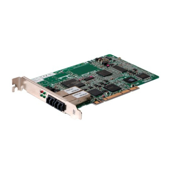
Page 52: Part Names And Settings
PROCEDURES AND SETTINGS BEFORE OPERATION Part Names and Settings This section explains each part name and setting of the CC-Link IE Controller Network board. Q80BD-J71GP21-SX < > RUN ERR. BD808C 318G51 Q80BD-J71GP21S-SX < > E.PW E.PW ERR. E.PW +24VDC BD808C 317G51 5.2 Part Names and Settings... - Page 53 PROCEDURES AND SETTINGS BEFORE OPERATION Q81BD-J71GP21-SX < > RUN ERR. BD808C 318G51 Q81BD-J71GP21S-SX < > E.PW E.PW ERR. E.PW +24VDC BD808C 317G51 5.2 Part Names and Settings...
- Page 54 PROCEDURES AND SETTINGS BEFORE OPERATION Name Description Indicates the operating status of the CC-Link IE Controller Network board. Indicator LED (1) in this section Connector for connecting optical fiber cable The cable terminal is as shown below. IN Reverse loop transmission IN Forward loop reception Optical fiber cable connector...
- Page 55 PROCEDURES AND SETTINGS BEFORE OPERATION (1) Indicator LED Display the operating status of the CC-Link IE Controller Network board. RUN ERR. (a) When the RUN LED is ON or OFF The same LED display as a network module. Name Status Description Operating normally One of the following error has occurred.
- Page 56 PROCEDURES AND SETTINGS BEFORE OPERATION (2) External power supply Display the status of external power supply. E.PW Name Status Description External power supply is not supplied. E.PW External power supply is being supplied. 5.2 Part Names and Settings...
-
Page 57: Installation
PROCEDURES AND SETTINGS BEFORE OPERATION Installation This section explains precautions for handling and installation environment of the CC-Link IE Controller Network board. 5.3.1 Handling precautions The following explains precautions for handling the CC-Link IE Controller Network board. Do not touch any connectors while power is on. Doing so may cause WARNING electric shock or malfunction. -
Page 58: Installation Environment
PROCEDURES AND SETTINGS BEFORE OPERATION 5.3.2 Installation environment For installation of the personal computer in which the CC-Link IE Controller Network board is installed, refer to the manual for the personal computer. Use the board in an environment that meets the general specifications in CAUTION this manual. -
Page 59: Setting Channel Numbers
PROCEDURES AND SETTINGS BEFORE OPERATION Shut off the external power supply for the system in all phases before WARNING installing the board to or removing it from the personal computer. Failure to do so may result in electric shock or cause the board to fail or malfunction. -
Page 60: Wiring
PROCEDURES AND SETTINGS BEFORE OPERATION Wiring This section explains precautions for connecting cables to the CC-Link IE Controller Network board. (1) Precautions for general wiring Shut off the external power supply for the system in all phases before WARNING installing the board or starting wiring. Failure to do so may result in electric shock, damage to the product, or malfunction. - Page 61 PROCEDURES AND SETTINGS BEFORE OPERATION (3) Precautions for external power supply cable wiring Place the communication cable and the external power supply cable CAUTION connected to the board in a duct or clamp them. If not, dangling cables may swing or inadvertently be pulled, resulting in damage to the board or cables or malfunctions due to poor contact.
-
Page 62: Controller Network System
Type Model name (maker) Multi-mode fiber (GI) QG series (Mitsubishi electric system & service Co., Ltd.) (b) When connecting an optical fiber cable to the CC-Link IE Controller Network board, the cable bend radius is restricted. For details, check the specifications of the cable used. - Page 63 PROCEDURES AND SETTINGS BEFORE OPERATION (2) Cable connection (a) Connection method Connect an optical fiber cable between OUT and IN as shown below. Note that there is no need to connect the cables in the order of station numbers. Control station Normal station Normal station CC-Link IE...
-
Page 64: Wiring External Power Supply Cable
PROCEDURES AND SETTINGS BEFORE OPERATION 5.4.2 Wiring external power supply cable This section explains the method for connecting external power supply cable to the CC- Link IE Controller Network board with external power supply function. (1) Connection procedure The following flowchart shows a procedure for connecting external power supply cable. - Page 65 PROCEDURES AND SETTINGS BEFORE OPERATION (3) Making external power supply cable The following explains the method for making external power supply cable. (a) Crimping a contacting pin Using a crimp tool, crimp the cable and contacting pin. Set the contacting pin and cable in the grooves of the crimp tool, squeeze the handle, and make them stick together tightly.
-
Page 66: Test
PROCEDURES AND SETTINGS BEFORE OPERATION Test Before executing data link, check the CC-Link IE Controller Network board and cables. Select a test item using the mode setting on the "Parameter setting" screen in the CC IE Control utility. The CC-Link IE Controller Network board test has the following six types. Item Test type Description... -
Page 67: Bus I/F Test
PROCEDURES AND SETTINGS BEFORE OPERATION 5.5.1 Bus I/F test This test checks the hardware of the Bus I/F function of the CC-Link IE Controller Network board. (1) In the "Parameter setting" screen of the CC IE Control utility, set Mode to "Bus I/F test"... -
Page 68: H/W Test
PROCEDURES AND SETTINGS BEFORE OPERATION 5.5.2 H/W test This tests the hardware in the CC-Link IE Controller Network board. (1) In the "Parameter setting" screen of the CC IE Control utility, set Mode to "H/W test" and click the button. Setting (2) The following confirmation dialog box appears. -
Page 69: Self-Loopback Test
PROCEDURES AND SETTINGS BEFORE OPERATION 5.5.3 Self-loopback test This tests the hardware of the CC-Link IE Controller Network board alone, including the send/receive circuit of the transmission system and cables. (1) Connect optical fiber cables to the IN and OUT of the CC-Link IE Controller Network board. - Page 70 PROCEDURES AND SETTINGS BEFORE OPERATION (4) The result is displayed on Test result field of the "Board detail information" screen. <Normal completion> <Abnormal completion> If the test completes abnormally, replace the optical fiber cable and execute the test again. If it fails again, the CC-Link IE Controller Network board hardware may be faulty. Please consult your local Mitsubishi representative, explaining a detailed description of the problem.
-
Page 71: Circuit Test
PROCEDURES AND SETTINGS BEFORE OPERATION 5.5.4 Circuit test This test checks the cable connection status and line status in the network system and parameter setting status of each station from the control station. The following explains a procedure for circuit test, assuming the executing station is the CC-Link IE Controller Network board and the target station as the CC-Link IE Controller Network module. - Page 72 PROCEDURES AND SETTINGS BEFORE OPERATION (4) Test mode settings (a) Setting the executing station Set as follows on the "Parameter setting" screen of the CC IE Control utility. Network type: CC IE Control (Control station) Mode: Circuit test Station No.: Station number for the executing station Setting (b) Setting the target station In the network parameter of GX Works2, set the mode to Online.
- Page 73 PROCEDURES AND SETTINGS BEFORE OPERATION (6) Checking the test result The result is displayed on Test result field of the "Board detail information" screen. <Normal completion> <Abnormal completion> If the test completes abnormally, check the error cause on the "CC-Link IE Controller Network diagnostics result"...
-
Page 74: Station-To-Station Test
PROCEDURES AND SETTINGS BEFORE OPERATION 5.5.5 Station-to-station test This test checks the cable connected between two stations (from OUT at the executing station to IN at the target station). The following explains a procedure for station-to station test, assuming the executing station is the CC-Link IE Controller Network board and the target station as the CC-Link IE Controller Network module. - Page 75 PROCEDURES AND SETTINGS BEFORE OPERATION (b) Setting the target station In the network parameter of GX Works2, set the mode to Online. *1: If the CC-Link IE Controller Network board is the target station, set as follows on the "Parameter setting"...
-
Page 76: Communication Test
PROCEDURES AND SETTINGS BEFORE OPERATION 5.5.6 Communication test Communication test is a test to check whether the transient transmission can be routed correctly between the own station and specified communication target. Note that, however, this test cannot be used during the circuit test. The following explains the procedure for a communication test. - Page 77 PROCEDURES AND SETTINGS BEFORE OPERATION (3) Set the items shown below, and click the button to execute Execute test the communication test. Section 8.5.2 Communication test screen Setting items Click (4) When the communication test is completed, a communication test result is displayed.
-
Page 78: Chapter 6 Parameter Settings
PARAMETER SETTINGS CHAPTER 6 PARAMETER SETTINGS It is necessary to set the parameters using the CC IE Control utility in order to operate the CC-Link IE Controller Network. The following is a flow chart for setting parameters. Board information settings Section 6.1 Parameter Settings (1) Channel No. - Page 79 PARAMETER SETTINGS Parameter Settings (Board Information Settings) This function is used to set a channel number, network type, and other settings of the CC- Link IE Controller Network board to be used. The parameter settings are set on the "Parameter setting" screen in the CC IE Control utility.
- Page 80 PARAMETER SETTINGS <Assigning channel numbers to the CC-Link IE Controller Network boards> The followings are the cases for assigning channel numbers to the CC-Link IE Controller Network boards. (a) When the boards are activated for the first time after the software package is installed.
- Page 81 PARAMETER SETTINGS (b) Only changing the channel number on the "Parameter setting" screen. Even when the channel number of Board 1 is changed to 153, it is still assigned to Board 1. Board 1 operates with the channel number 153. (c) Restarting the personal computer after changing the channel number on the "Parameter setting"...
- Page 82 PARAMETER SETTINGS (4) Operational setting Set a network number, station number, control station/normal station and group number of the CC-Link IE Controller Network board. (a) Network type Set a station type of the CC-Link IE Controller Network board. Max. link points per Item Description station for LB/LW...
- Page 83 PARAMETER SETTINGS Select item Description Reference Checks the cable connection status of the network, circuit Circuit test status, and parameter setting status of each station from Section 5.5.4 the control station. Test between Checks the cable status connected between two stations Section 5.5.5 station (master station OUT to slave station IN).
- Page 84 PARAMETER SETTINGS (c) Network No. Set a network number of the network to which the CC-Link IE Controller Network board is connected. 1) Valid setting range 1 to 239 2) Precaution Set a same network number to all devices that are connected to the same network.
-
Page 85: Parameter Setting Example
PARAMETER SETTINGS Parameter Setting Example The following shows the parameter setting example of the CC-Link IE Controller Network board. (1) System example Control Station 1) port No. 151 CC-Link IE Controller Network Network No.1 (2) Setting screen Settings for Control station (1M 6.2 Parameter Setting Example... -
Page 86: Network Range Assignment Settings
PARAMETER SETTINGS Network Range Assignment Settings This function is used to set cyclic transmission ranges of devices, LB, LW, LX, and LY, that can be sent by each station in a single network connected to the CC-Link IE Controller Network board. The settings are required only for the control station. -
Page 87: Lb/Lw Settings
PARAMETER SETTINGS 6.3.1 LB/LW settings Set each station's send range in LB/LW to use it for the cyclic transmission. (1) Setting "LB/LW settings (1)" and "LB/LW settings (2) separately" LB/LW settings can be divided into "LB/LW settings (1)" and "LB/LW settings (2)". Normally, setting only "LB/LW settings (1)"... - Page 88 PARAMETER SETTINGS (4) Setting example Network No.1 (a) When assigning 512 points to each station's send range in LB/LW ("LB/LWsettings (1)") Network range assignment LB/LW setting Link relay (LB) Station No.1 No.1 send range Station No.1 Station No.1 Station No.1 LB0 to LB1FF LB200 to LB3FF No.2...
- Page 89 PARAMETER SETTINGS (b) When extending the send range of station No.1 to 1024 points without changing the assignment shown in (a). ("LB/LW settings (2)") Network range assignment LB/LW setting Link relay (LB) LB0 to LB1FF Station No.1 No.1 send range Station No.1 Station No.1 Station No.1...
-
Page 90: Lx/Ly Settings
PARAMETER SETTINGS 6.3.2 LX/LY settings For each block, set an I/O master station and I/O ranges used in the cyclic transmission between the I/O master and relevant stations. (1) Setting "LX/LY settings (1)" and "LX/LY settings (2)" separately Set "LX/LY settings (1)" as block 1 and "LX/LY settings (2)" as block 2. POINT •... - Page 91 PARAMETER SETTINGS (2) Setting example The following example shows the I/O ranges of LX/LY for each station, when the station number 1 is set as the I/O master station in block 1, and 512 points are assigned to station number 2 to 4. ("LX/LY setting (1)") Network No.1 1000 1000...
-
Page 92: Total Number Of Link Stations
PARAMETER SETTINGS 6.3.3 Total number of link stations Set the total number of link stations for a single network when "CC IE Control (Control station)" or "CC IE Control Extended mode (Control station)" is selected in the "Network type" field. 6.3.4 Specifying I/O master station The I/O master station (control station) which is used for one-to-one communication by LX/... -
Page 93: Specifying Reserved Stations
PARAMETER SETTINGS 6.3.5 Specifying reserved stations This function is used to reserve stations (stations not actually connected, but included in the total number of stations) to be connected afterward. The reserved stations are not recognized as faulty stations. 6.3 Network Range Assignment Settings - 16 6.3.5 Specifying reserved stations... -
Page 94: Equal Assignment Settings
PARAMETER SETTINGS Equal Assignment Settings This function is used to assign devices automatically in the network range. The equal assignment settings are set on the "Equal assignment" screen in the CC IE Control utility. Section 8.4.3 Equal assignment screen The following shows the two types of equal assignment. Assignment Description method... - Page 95 PARAMETER SETTINGS <Setting example> (1) Equally assigning LB0 to 1FF (512 points) to the send ranges of station number 1 to 4. Select "Equal assignment" and enter following values. Start station: 1 End station: 4 Start No.: 0000 Total points assigned: 512 Devices are equally assigned in the "LB/LW setting (1)"...
- Page 96 PARAMETER SETTINGS (3) Assigning identical points of 128 to the LB/LW send ranges for each station. Select "Identical point assignment" and enter 128. Identical points are assigned in the "LB/LW setting (1)" field of the "Network range assignment" screen. (4) Assigning identical points of 128 to the LX/LY send ranges for each station.
-
Page 97: Routing Parameter Settings
PARAMETER SETTINGS Routing Parameter Settings The transmission target and relay stations of the transient transmission are set in the routing parameter settings. CC-Link IE Controller Network boards cannot be used as relay stations. (For relay stations, set the network modules controlled by the programmable controller CPU.) The routing parameter settings are set on the "Routing parameter setting"... -
Page 98: Supplementary Settings
PARAMETER SETTINGS Supplementary Settings The supplementary settings are included in the Network range assignment setting, and it is used to set more detailed settings. Use the initial settings in general. The supplementary settings (parameter settings) are required only for the control station. The parameters are sent from the control station to normal stations at start up of the network. -
Page 99: Driver Settings
PARAMETER SETTINGS Driver Settings This function is used to set the refresh cycle of the cyclic transmission and monitoring time of the transient transmission. The driver settings are set on the "Driver setting" screen in the CC IE Control utility. Section 8.4.6 Driver setting screen 6.7 Driver Settings - 22... -
Page 100: Event Settings
PARAMETER SETTINGS Event Settings This function is used to set the conditions for monitoring link device changes using the CC- Link IE Controller Network board to notify events to the user program. The event settings are set on the "Event setting" screen in the CC IE Control utility. Section 8.4.7 Event setting screen - 23 6.8 Event Settings... -
Page 101: Target Settings
PARAMETER SETTINGS Target Settings This function is used to set logical numbers for accessing the multiple CPU system or redundant CPU system. The target settings are set on the "Target setting" screen in the CC IE Control utility. Section 8.4.8 Target setting screen (1) Setting example when accessing the multiple CPU system CPU No.2 CC-Link IE Controller Network module... -
Page 102: Refresh Parameter Setting
PARAMETER SETTINGS 6.10 Refresh Parameter Setting The refresh parameters are designed to transfer link devices (LX, LY, LB, and LW) of CC- Link IE Controller Network board to the driver buffers (LX, LY, LB, and LW buffers) of a personal computer to be used in user programs. The refresh parameter settings are set on the "Refresh parameter setting"... -
Page 103: Chapter 7 Installing And Uninstalling Software Packages
INSTALLING AND UNINSTALLING SOFTWARE PACKAGES CHAPTER 7 INSTALLING AND UNINSTALLING SOFTWARE PACKAGES This chapter explains about installing and uninstalling the software packages, and icons to be registered. Installation and Uninstallation Precautions The following are the precautions when installing and uninstalling the software package. •... -
Page 104: Installation
INSTALLING AND UNINSTALLING SOFTWARE PACKAGES Installation This section explains a procedure for installing software package. (1) Installation 1) Insert the CD-ROM to the CD-ROM drive. 2) Double click the "Setup.exe" file on the CD-ROM. 3) By following the on-screen instructions, select or enter the necessary information. - Page 105 INSTALLING AND UNINSTALLING SOFTWARE PACKAGES (b) MELSEC Data Link Library MELSEC data link library is used for the following software packages in common. When the utilities are installed on the same personal computer, the newer MELSEC data link library of the software package is enabled. •...
-
Page 106: Uninstallation
INSTALLING AND UNINSTALLING SOFTWARE PACKAGES Uninstallation This section explains a procedure for uninstalling the software package. (1) Uninstallation procedure ® 1) Uninstall the software package from the control panel of Windows POINT • If the dialog box confirming the deletion of common files appears at uninstallation, make the setting to keep all common files. -
Page 107: Chapter 8 Cc Ie Control Utility
This section explains the settings on the CC IE Control utility screen and its operating methods. ® Q80BD-J71GP21-SX and the CC IE Control utility installed under Windows Professional Operating System are used for screen explanations. POINT Log on as a user having administrator authority. -
Page 108: List Of Functions
CC IE Control UTILITY 8.1.1 List of functions The following table explains the functions of the CC IE Control utility. Function Description Reference Monitors operating information and hardware information of the CC- Board list Section 8.3.1 Board Link IE Controller Network board. information Channel confirm Confirm channel numbers that are set to each station. -
Page 109: Operating Procedure
CC IE Control UTILITY Operating Procedure This section explains the operating procedure of the CC IE Control utility. Start Connect the personal computer to the CC-Link IE Controller Network. Section 5.1 Procedure before Operation Start the CC IE Control utility. Section 8.2.1 Starting the utility Set the channel number and operation settings (network type, mode, network number, group number, and station number) of the target... -
Page 110: Starting The Utility
CC IE Control UTILITY 8.2.1 Starting the utility Start the CC IE Control utility by clicking [MELSEC] - [CC IE Control Utility (Board)] registered in the "Start" of Windows. [Start screen] - [All apps] or [Start] - [All Programs] POINT (1) Only one utility can be run. -
Page 111: Ending The Utility
CC IE Control UTILITY 8.2.2 Ending the utility To end the CC IE Control utility, select the button at the bottom of the board list Close screen (start screen). Click 8.2.3 Displaying manual This manual is displayed by clicking the button on the bottom of the Board list Manual screen (start screen). -
Page 112: Checking The Version Information
CC IE Control UTILITY 8.2.4 Checking the version information To check the version information of the CC IE Control utility, click the icon on the board list screen (start screen) and click [Version information] in the system menu. Click 8.2 Operating Procedure 8.2.4 Checking the version information... -
Page 113: Board Information Screens
CC IE Control UTILITY Board Information Screens This section explains about the screens which display the parameter information and online status of the CC-Link IE Controller Network board. 8.3.1 Board list screen The board list screen is displayed containing the own station information of the CC-Link IE Controller Network board, when starting the CC IE Control utility. - Page 114 CC IE Control UTILITY Item Description Display content — Displays the system menu. (System menu) Displays channel numbers of the CC-Link IE Controller Channel No. 151 to 154 Network board. Displays network numbers of the CC-Link IE Controller Network No. 1 to 239 Network board.
-
Page 115: Channel Number Confirmation Screen
CC IE Control UTILITY 8.3.2 Channel number confirmation screen This screen is displayed by clicking the button on the board list screen Channel confirm (start screen). Section 8.3.1 Board list screen It is used to check channel numbers displayed in LED display status of the CC-Link IE Controller Network board. -
Page 116: Board Detail Information Screen
(start screen). Section 8.3.1 Board list screen It is used to display the detail information on the CC-Link IE Controller Network board. Item Description Display content Q80BD-J71GP21-SX Q80BD-J71GP21S-SX Displays the type of connected CC-Link IE Controller Board type Q81BD-J71GP21-SX Network board. -
Page 117: Memory Test Screen
CC IE Control UTILITY 8.3.4 Memory Test screen This screen is displayed by clicking the button on the Board detail Memory Test information screen. Section 8.3.3 Board detail information screen This operation diagnoses between CC-Link IE Controller Network board and personal computer. -
Page 118: Setting Screen
CC IE Control UTILITY Setting Screen This section explains about the screens which are used to set parameters of the CC-Link IE Controller Network board. 8.4.1 Parameter setting screen This screen is displayed by clicking the button on the board list screen (start Setting screen). - Page 119 CC IE Control UTILITY Item Description Default Setting range CC IE Control (Control station) CC IE Control (Normal station) Network CC IE Control CC IE Control Set a network type of the target board. type (Control station) Extended mode (Control station) CC IE Control Extended mode (Normal station)
- Page 120 CC IE Control UTILITY Item Description Default Setting range Saves the parameter settings set in the CC IE Control utility to the personal computer, resets the *2 *3 *4 — — CC-Link IE Controller Network board, and closes the "Parameter setting" screen. Without saving the parameter settings set in the CC IE Control utility to the personal computer, closes —...
-
Page 121: Network Range Assignment Screen
CC IE Control UTILITY 8.4.2 Network range assignment screen This screen is displayed by clicking the button on the Network range assignment "Parameter setting" screen. Section 8.4.1 Parameter setting screen It is used to set the cyclic transmission ranges of LB, LW, LX, and LY that can be sent by each station. - Page 122 CC IE Control UTILITY Item Description Default Setting range Starts the "Supplementary setting" screen. Section 8.4.5 Supplementary setting — — Supplementary setting screen Clears the parameter settings of network range — — Clear assignment, and sets default settings. Checks for errors in the parameters of the —...
-
Page 123: Equal Assignment Screen
CC IE Control UTILITY 8.4.3 Equal assignment screen This screen is displayed by clicking the button on the "Network range Equal assignment assignment" screen. Section 8.4.2 Network range assignment screen It is used to set the network range assignment for each station in identical points or equal points. - Page 124 CC IE Control UTILITY Device Item Setting range Start number 0000 to 7FF0 (units of 16 points, hexadecimal input) Total points assigned 16 to 32768 (units of 16 points) Start number 00000 to 1FFFF (units of 1 point, hexadecimal input) Total points assigned 1 to 131072 (units of 1 point) Start number 0000 to 1FF0 (units of 16 points, hexadecimal input)
-
Page 125: Routing Parameter Setting Screen
CC IE Control UTILITY 8.4.4 Routing parameter setting screen This screen is displayed by clicking the button on the "Parameter Routing parameter setting" screen. Section 8.4.1 Parameter setting screen It is used to set the target network number, relay network number, and relay station number. -
Page 126: Supplementary Setting Screen
CC IE Control UTILITY 8.4.5 Supplementary setting screen This screen is displayed by clicking the button on the "Network Supplementary setting range assignment" screen. Section 8.4.2 Network range assignment screen It is used to set the constant link scan time, block data assurance per station, punctuality assurance, and maximum number of transients in one station. -
Page 127: Driver Setting Screen
CC IE Control UTILITY 8.4.6 Driver setting screen This screen is displayed by clicking the button on the "Parameter setting" Driver setting screen. Section 8.4.1 Parameter setting screen It is used to set the driver WDT monitoring time, time-out time and link refresh cycle. Item Description Default... - Page 128 CC IE Control UTILITY POINT The link refresh method is a method to access the CC-Link IE Controller Network driver buffer. The data in the link refresh storage area of the CC-Link IE Controller Network driver buffer and the CC-Link IE Controller Network board are updated by the link refresh function.
-
Page 129: Event Setting Screen
CC IE Control UTILITY 8.4.7 Event setting screen This screen is displayed by clicking the button on the "Parameter setting" Event setting screen. Section 8.4.1 Parameter setting screen This function is used to set the conditions for monitoring link device changes using the CC- Link IE Controller Network board to notify events to the user program. - Page 130 CC IE Control UTILITY Item Description Default Setting range Checks the event settings. — — Check Reflects the settings, and closes the "Event — — setting" screen. Without reflecting the settings, closes the — — Cancel "Event setting" screen. *1: Set the device number and device points -1 not to exceed the range of device number. *2: Cannot be set when the "Event condition"...
-
Page 131: Target Setting Screen
CC IE Control UTILITY 8.4.8 Target setting screen This screen is displayed by clicking the button on the "Parameter setting" Target setting screen. Section 8.4.1 Parameter setting screen It is used to set logical station numbers for accessing the multiple CPU system or redundant CPU system. - Page 132 CC IE Control UTILITY POINT When a CC-Link IE Controller Network board with a serial number whose first five digits are 10091 or lower, or an SW1DNC-MNETG-B with the software version 1.04E or earlier is used, the redundant CPU system cannot be accessed directly with the CC-Link IE Controller Network interface board.
-
Page 133: Refresh Parameter Setting Screen
CC IE Control UTILITY 8.4.9 Refresh parameter setting screen This screen is displayed by clicking the button on the "Parameter Refresh parameter setting" screen. Section 8.4.1 Parameter setting screen It is used to set device ranges to execute refreshes. Item Description Default Setting range... - Page 134 CC IE Control UTILITY Item Description Default Setting range Without reflecting the settings, closes the "Refresh — — Cancel parameter settings" screen. *1: The initial values of the refresh parameter setting are indicated in the following table. Setting item Device name Points Start Trans.1...
-
Page 135: Diagnostics Screen
CC IE Control UTILITY Diagnostics Screen This section explains about the screens which are used to check the link status and station status of the network. 8.5.1 CC-Link IE Controller Network diagnostics result screen This screen is displayed by clicking the button on the board list screen (start Diagnostics screen). - Page 136 CC IE Control UTILITY Item Description Displays the "Select diagnostics destination" screen when two or more CC-Link IE Controller Network boards are installed in the personal computer. Change board Change the target network for diagnostics. Changes to the entered station number by clicking the button.
- Page 137 CC IE Control UTILITY (2) Icon Displays the status of each station and between stations. 1 Connected Present Control Assign Control 1) Station number Displays station number of the CC-Link IE Controller Network module or CC- Link IE Controller Network board. 2) Connected station "Connected"...
- Page 138 CC IE Control UTILITY (3) Display position of disconnected station (a) When normal connection information has been obtained The disconnected station is displayed in the position where it was connected when operated normally. 1) Conditions and timing for normal connection information acquisition When all of the following conditions are met, the normal connection information is stored in the CC-Link IE Controller Network module.
- Page 139 CC IE Control UTILITY (4) Select station network device status display Displays detailed information of the selected station. For boards For modules Item Description Display content Group No. Displays a group number of the selected station. 0 to 32 Online Offline H/W test Mode...
- Page 140 CC IE Control UTILITY (5) Select station network device status LED display Displays the LED status on the top part of the CC-Link IE Controller Network module and CC-Link IE Controller Network board according to the device status in the "Select station network device status display"...
- Page 141 CC IE Control UTILITY (6) Error details buttons Displays the "Error details" screen by clicking the button. Displays detail information, error factor, and troubleshooting. 8.5 Diagnostics Screen - 35 8.5.1 CC-Link IE Controller Network diagnostics result screen...
-
Page 142: Communication Test Screen
CC IE Control UTILITY 8.5.2 Communication test screen This screen is displayed by clicking the button on the "CC-Link IE Communication test Controller Network diagnostics result" screen. Section 8.5.1 CC-Link IE Controller Network diagnostics result screen It is used to display the path from the own station to specified communication target, and check whether the transient transmission can be routed correctly in the network. - Page 143 CC IE Control UTILITY Item Description Set/Display Communication information Displays the communication information. — Communication count Displays the number of communications. 1 to 100 Communication time Displays the communication time. 1 to Destination Displays the information of the communication target. —...
-
Page 144: Link Start/Stop Screen
CC IE Control UTILITY 8.5.3 Link start/stop screen This screen is displayed by clicking the button on the "CC-Link IE Link start/stop Controller Network diagnostics result" screen. Section 8.5.1 CC-Link IE Controller Network diagnostics result screen It is used to start and stop the data link of the specified station. Item Description Display content... - Page 145 CC IE Control UTILITY Item Description Default Setting range Link start/stop Specifies link start and stop. — — Link start Select to execute link start to the selected station. Link stop Select to execute link stop to the selected station. Select to execute forced link start to the selected Force link start station.
-
Page 146: Logging Screen
CC IE Control UTILITY 8.5.4 Logging screen This screen is displayed by clicking the button on the "CC-Link IE Controller Logging Network diagnostics result" screen. Section 8.5.1 CC-Link IE Controller Network diagnostics result screen It is used to monitor the transmission path switch of the connected stations and transient transmission error history. - Page 147 CC IE Control UTILITY Item Description Default Set/Display Displayed when a transient transmission error — — Transient transmission error occurs. Error code Displays a transient error code. — — Displays the network number of transient request Target Net — 1 to 239 target when the transient error occurred.
-
Page 148: Chapter 9 Device Monitor Utility
DEVICE MONITOR UTILITY CHAPTER 9 DEVICE MONITOR UTILITY For the operation and setting method for the device monitor utility, refer to "MELSEC Data Link Library Reference Manual". - Page 149 DEVICE MONITOR UTILITY Memo...
-
Page 150: Chapter 10 Melsec Data Link Library
MELSEC DATA LINK LIBRARY CHAPTER 10 MELSEC DATA LINK LIBRARY This chapter explains the features of the functions provided by the library. The functions are used when creating a user program that communicates with a programmable controller CPU. With these functions, a user can communicate without being aware of hardware types or communication protocols on the target. - Page 151 MELSEC DATA LINK LIBRARY The following table shows the list of the functions in the MELSEC data link library that is provided with the software package. Function name Description mdOpen Opens a communication line. mdClose Closes a communication line. Batch writes devices. (Extended function mdSendEx Sends data.
-
Page 152: Chapter 11 Programming
PROGRAMMING CHAPTER 11 PROGRAMMING 11.1 Precautions on Programming This section explains the precautions on creating programs using data on a network. 11.1.1 Interlock related signals The following table shows a list of the interlock signal devices used in a user program. For details of other devices to check the operating status, setting status, and other functions of the own station and other stations, refer to the following manual. - Page 153 PROGRAMMING Device status Device Name Description OFF (0) ON (1) Stores a cyclic transmission status of each station. If a station that has not executed the cyclic Cyclic All stations are Cyclic transmission transmission is found, the station number is transmission not- SB00B0 status of each...
-
Page 154: Cyclic Transmission
PROGRAMMING 11.2 Cyclic Transmission The link scan of the CC-Link IE Controller Network and the execution of the user program are operated asynchronously. When using data more than 32 bits (double words) indicated below, new data and old data may be mixed in units of 16 bits (1 word) depending on the execution timing of a user program. -
Page 155: Station-Based Block Data Assurance
PROGRAMMING 11.2.1 Station-based block data assurance Block data are assured per station by handshaking between the personal computer and CC-Link IE Controller Network board, and executing the link refresh. Station-based block data assurance (link data separation prevention by each station ) is executed by the handshake of cyclic data. -
Page 156: Link Special Relays (Sb) And Link Special Registers (Sw)
PROGRAMMING 11.3 Link Special Relays (SB) and Link Special Registers (SW) The information when linking data is stored in link special relays (SB) and link special registers (SW). Faulty areas and causes of errors can be investigated by using and monitoring the information in a user program. -
Page 157: Chapter 12 Application Functions
APPLICATION FUNCTIONS CHAPTER 12 APPLICATION FUNCTIONS Basic functions Cyclic transmission function Communication by LB/LW (Periodical communication) Communication by LX/LY Assurance of cyclic data integrity (Block data assurance per station (station-based block data assurance)) Cyclic transmission punctuality assurance Constant link scan Control station switching function CC-Link IE Controller Network RAS functions... - Page 158 APPLICATION FUNCTIONS 12.1 Transient Transmission Function This function performs data communication with other station's programmable controller when a request is made from the MELSEC Data Link Library. Chapter 10 MELSEC DATA LINK LIBRARY Communication can be made with programmable controllers on the same or other networks.
-
Page 159: Transient Transmission Function
APPLICATION FUNCTIONS 12.1.1 Communication function (1) Supplementary setting Set the execution conditions for the transient transmission. (a) Constant scan Set a time for constant link scan. (b) Block data assurance per station Set whether to guarantee cyclic data in station units. When the "Block data assurance per station is available"... -
Page 160: Communication Function
APPLICATION FUNCTIONS (2) Transient transmission range In a multiple network system of the CC-Link IE Controller Network, communication can be performed with a station in a maximum of eight networks away by setting the routing parameters. Section 12.1.2 Routing function (Relay station 1) (Relay station 2) (Relay station 3) - Page 161 APPLICATION FUNCTIONS [Transient transmission valid range] The following table shows the valid ranges of transient transmission using the network configuration on the previous page. In the table below, , , and indicate whether the transient transmission between the request source (destination) listed in the column at the left and the request destination (source) listed in the row at the bottom is possible.
-
Page 162: Routing Function
APPLICATION FUNCTIONS 12.1.2 Routing function The routing function allows the transient transmission to a station located on another network number in a multiple network system. In order to execute the routing function, it is necessary to set the "routing parameters" to associate the network number of the request source and the station that functions as a relay station. - Page 163 APPLICATION FUNCTIONS (3) Stations that require routing parameter setting (a) The setting is required for both the transient transmission request source and relay stations. (b) For the relay stations, two routing settings are required: one from the request source to the request target, and the other from the request target back to the request source.
- Page 164 APPLICATION FUNCTIONS (4) Routing parameter setting (a) Setting screen Up to 64 "Target Network No." can be set on the "Routing Parameter Setting" screen of the CC IE Control utility. The same target network number cannot be set more than one (multiple). For this reason, the own station may become a request source, and up to 64 types of "Target Network No."...
- Page 165 APPLICATION FUNCTIONS (b) Setting method Set the routing parameters according to the procedure described below. Request source Network No. Relay station Network No. Request target To access the station in "Network No. ", the station No. of Network No. must be relayed first. Target Relay Relay...
- Page 166 APPLICATION FUNCTIONS (5) Setting required stations and contents for different network system configurations The stations and contents of the routing parameter setting for the transient transmission depend on the system configuration. (a) Single network system The routing parameter setting is not required for the transient transmission within the same network.
- Page 167 APPLICATION FUNCTIONS POINT (1) When networks are connected in a loop as shown in the figure below, make sure to set the routing parameters so that the same relay stations are routed for both the "route from the request source to the request target" and the "route back from the request target to the request source".
- Page 168 APPLICATION FUNCTIONS (6) Setting example The routing parameter setting examples (A and B) are explained using the system configuration described in Section 12.1.1(2). 2) Relay station 3) Relay station 4) Relay station QCPU QCPU QCPU 2 3N QCPU 2 4M Network No.1 Network No.2 Network No.3...
- Page 169 APPLICATION FUNCTIONS (b) Setting example B The routing parameter setting is required for the request source1), relay station 2), relay station 3), relay station 4), relay station 5), relay station 6), relay station 7), and relay station 8). In addition, two types of routing parameters can be set; one is for sending data from the request source to the request target (when sending a request), and the other for returning from the request target to the request source (when sending a response).
- Page 170 APPLICATION FUNCTIONS (7) Calculation of transmission delay time The processing time to access a station on another network using the MELSEC Data Link Library functions in a multiple network system can be obtained by adding the following transmission delay factors. (Routing transmission delay time) = (processing time from request source to relay station) + (processing time from relay station to request target) (a) Processing time from request source to relay station...
-
Page 171: Group Function
APPLICATION FUNCTIONS 12.1.3 Group function This function specifies transient transmission target stations as a group and transmits data to all stations in a group with a single transient transmission. One network can be divided into up to 32 groups. This function is used for the Network diagnostics on the CC-Link IE Controller Network board. -
Page 172: Send/Recv Function
APPLICATION FUNCTIONS 12.1.4 SEND/RECV function The SEND/RECV function sends/receives data to/from other station's programmable controller using the MELSEC data link library function. This function supports the SEND/RECV instruction of link dedicated instruction. POINT For details of the functions, refer to the following manual. MELSEC Data Link Library Reference Manual (1) SEND function The SEND function sends data from the own station to the specified channel of the... - Page 173 APPLICATION FUNCTIONS POINT (5) The multiple network modules are installed on the target station Specify the network number and station number of the network module which is to be received request from the own station. Specify 1N 2 in the following example.
- Page 174 APPLICATION FUNCTIONS (2) RECV function The RECV function reads data received by the board from the other station using the mdReceive/mdReceiveEx function. < RECV function overview > Driver User application Reception buffer of driver Received data storage (data) Received data of Channel 3 Send source network No.
- Page 175 APPLICATION FUNCTIONS < Precautions for using RECV function > When receiving data to the multiple channels of the board, create a user program to read data from all channels that receive data. If a channel from which data are not read exists in the channel from which data are received, the received data of the channel from which data are not read are accumulated in the reception buffer of the driver and all area of 128 data are occupied.
-
Page 176: Event Setting Function
APPLICATION FUNCTIONS 12.2 Event Setting Function The event function monitors link devices using the CC-Link IE Controller Network board, and notifies events to the user program when the set conditions are met. By using this function, the link devices can be monitored efficiently without reading link devices regularly by the user program. - Page 177 APPLICATION FUNCTIONS POINT (1) Events are notified every link refresh cycle. Section 8.3.3 Board detail information screen Section 8.4.6 Driver setting screen (2) Set the refresh parameter as link devices for monitoring are included in the refresh range. If they are not included in the refresh range, events are notified, but the devices for monitoring cannot be accessed.
-
Page 178: Chapter 13 Error Codes
ERROR CODES CHAPTER 13 ERROR CODES This chapter explains error codes and error messages returned when errors occur. For error codes of the MELSEC data link library functions, refer to the following manual. MELSEC Data Link Library Reference Manual 13.1 List of Error Messages in CC IE Control Utility The following explains the corrective actions to error messages in the CC IE Control utility. -
Page 179: Error Messages Displayed On The Board Information Screen
ERROR CODES 13.1.1 Error messages displayed on the board information screen (1) Board list screen (start screen) Error message Corrective action Only one CC IE Control utility can be started. The CC IE Control utility has already been activated. CC IE Control utility has already been started. Execute after completing the activated CC IE Control utility. -
Page 180: Error Messages Displayed On The Setting Screen
ERROR CODES 13.1.2 Error messages displayed on the setting screen (1) Parameter setting screen Error message Corrective action Failed to read parameters. The probable causes are: • Write the parameters. • Parameters have not been set. • Check the H/W failure on the CC-Link IE Controller •... - Page 181 ERROR CODES (2) Network range assignment screen Error message Corrective action The I/O master station set/erase station No. is not selected. Select one station number only, and press the I/O master Please select the I/O master station set/erase station No. station specification button.
- Page 182 ERROR CODES (3) Equal assignment screen Error message Corrective action The equally assigned end station setting value is outside the Set the value for the equally assigned end station within the range. range of XX to YY. Please input a value within the range XX-YY. The equally assigned start station setting value is outside the Set the value for the equally assigned start station within the range.
- Page 183 ERROR CODES (7) Event setting screen Error message Corrective action The event No. is outside the range. Set the value for the event number within the range of 0 to 63. Please input a value within the range 0-63. The device No. is outside the range. Set the values for the device number within the following Please input each device within the following ranges.
-
Page 184: Error Messages Displayed On The Diagnostics Screen
ERROR CODES 13.1.3 Error messages displayed on the diagnostics screen (1) CC-Link IE Controller Network diagnostics result screen Error message Corrective action • Restart the CC IE Control utility. Retrieving window creation failed. Network diagnostics will • The installation of SW1DNC-MNETG-B may be failed. now end. - Page 185 ERROR CODES (2) Communication test screen Error message Corrective action Communication test was not normally done. Check the settings of the routing parameter. Specify the value for the network number within the range of Network No. value is not entered. 1 to 239.
- Page 186 ERROR CODES (3) Link start/stop screen Error message Corrective action Target station is not selected. Select the target station. After selecting, execute it again. • Set the network parameters correctly. • Restart the CC IE Control utility. Network type cannot be retrieved. •...
- Page 187 ERROR CODES (4) Logging screen Error message Corrective action The item to clear is not selected. After selecting the item, Select the item to be cleared. execute it again. • Set the network parameters correctly. • Restart the CC IE Control utility. Unexpected error occurred.
-
Page 188: List Of Error Messages In Device Monitor Utility
ERROR CODES 13.2 List of Error Messages in Device Monitor Utility The following explains the corrective actions to error messages in the Device monitor utility. Error message Corrective action DEC input range error. Input a decimal number in the range of 0 to 9. Input 0-9. -
Page 189: Chapter 14 Troubleshooting
TROUBLESHOOTING CHAPTER 14 TROUBLESHOOTING This section explains the identification of the causes and corrective actions when an error occurred. (1) Basic checking procedure Check if there is the corresponding error symptom depending on the situation. (Section 14.1) If the corresponding error could not be found, check the cause by following the procedure shown below. -
Page 190: Cause Determination Methods For Each Trouble
TROUBLESHOOTING 14.1 Cause Determination Methods for Each Trouble When a trouble occurs, refer to the table below for methods to determine the cause. Trouble description Determination method/Action The CC-Link IE Controller Network board did not normally operate at start-up. Refer to Section 14.3. When executing a user program, system down (blue screen) or system reset occurred on the operating system. - Page 191 TROUBLESHOOTING Trouble description Determination method/Action The User Account Control screen is displayed when the utility is activated. When the utility is activated, and if the following User Account Control screen is displayed requesting a selection of user with administration authority and password entry , the user who is logging on to the system does not have an administrator...
-
Page 192: Troubleshooting Of Installation/Uninstallation
TROUBLESHOOTING 14.2 Troubleshooting of Installation/Uninstallation The following explains the troubleshooting for error at installation or uninstallation. • Installation failed(Section 14.2.1) • Uninstallation failed(Section 14.2.2) 14.2.1 Installation failed When the installation is aborted or failed, reinstall the utility by the following procedure. 1. -
Page 193: Uninstallation Failed
TROUBLESHOOTING 14.2.2 Uninstallation failed When the uninstallation is failed, uninstall the utility after the reinstallation by the following procedure. 1. Check the installation/uninstallation precautions. Section 7.1 If the creation of 8.3 filename is disabled, perform the operation (1) in this section. 2. -
Page 194: When The Corrective Action Displayed On The Screen Is Not Effective At Installation
TROUBLESHOOTING 14.2.3 When the corrective action displayed on the screen is not effective at installation The following table shows the corrective actions when the screen is displayed. Screen Corrective action This screen is displayed when user account control is enabled. Click "Allow"... - Page 195 TROUBLESHOOTING Screen Corrective action Confirm the publisher is "MITSUBISHI ELECTRIC CORPORATION", and click the button. Install This screen may be displayed a couple of times. The message is displayed when .NET Framework 3.5 (including .NET 2.0 and 3.0) is set to disabled.
-
Page 196: When The Driver Is Not Installed
TROUBLESHOOTING 14.2.4 When the driver is not installed The driver is installed automatically when installing the board on the personal computer after installing the software package. When the "Found New Hardware Wizard" screen is not displayed automatically after the board installation, update the driver on the "Device Manager" screen. ®... -
Page 197: When Cc-Link Ie Controller Network Board Did Not Operate Normally
TROUBLESHOOTING 14.3 When CC-Link IE Controller Network Board did not Operate Normally When the personal computer on which the board is installed is not started, or the system shut down or system reset is occurred, check the items following the procedure shown below. -
Page 198: Checking On Event Viewer Screen
TROUBLESHOOTING 14.3.2 Checking on Event Viewer screen ® Check the operation of the board with Windows Event Viewer screen. Event logs related to the CC-Link IE Controller Network board are displayed as "AMnetg" or "Mccien" in the Source field on the Event Viewer screen. (1) For error events When an error occurs in a driver, the error description is displayed in the System Log field on the Event Viewer screen. - Page 199 TROUBLESHOOTING Event ID. Error message Corrective action • Remove another I/F board. 291(0123 Failed to map the shared memory area. • Change the I/O port address of another I/F board on the BIOS setting screen. • Remove another I/F board. The I/O port of the I/F board overlaps with 294(0126 •...
- Page 200 TROUBLESHOOTING (2) For information event The following "information event logs" other than errors are displayed in the System Log field on the Event Viewer screen. The corrective actions are not required for the following events. Event No. Description Output timing 1024(0400 Driver started normally.
-
Page 201: Checking On Device Manager Screen
TROUBLESHOOTING 14.3.3 Checking on Device Manager screen ® Check if the board is displayed on the Windows Device Manager screen. Item Corrective action The board or driver is not installed. • If the board is not installed, install the board. If the board is already installed, check the board installation status and reinstall the board. -
Page 202: Flowchart When Data Link Failed
TROUBLESHOOTING 14.4 Flowchart when Data Link Failed The following shows a check flowchart although the CC-Link IE Controller Network board, control station, and normal stations were connected, the data link failed. Start Check the LED on the CC-Link IE Controller Network board. -
Page 203: Flowchart When Run Led Is Off
TROUBLESHOOTING 14.4.1 Flowchart when RUN LED is OFF An error occurred. Did the LED turn OFF NO (The "RUN" LED has turned OFF since power-ON.) even during communications with other stations? Did the "RUN" LED turn ON after replacing the CC-Link IE Controller Network board? Check the hardware of the personal computer. -
Page 204: Flowchart When Sd/Rd Leds Are Off
TROUBLESHOOTING 14.4.2 Flowchart when SD/RD LEDs are OFF An error occurred. Section 14.4.3 Flowchart when ERR. Is the "ERR" LED ON? LED turned ON Does the Review the parameter setting. parameter set to the control station correct? Did the "RD" LED Did the "SD"... -
Page 205: Flowchart When Err. Led Turned On
TROUBLESHOOTING 14.4.3 Flowchart when ERR. LED turned ON An error occurred. Stop the user program and start the CC IE Control utility. Check "Present Error" on the "Board detail information" screen Section 8.3.3 Board detail information screen Is an error code displayed in the "Present Error"... -
Page 206: Flowchart When Data Link Among Whole System Is Disabled
TROUBLESHOOTING 14.4.4 Flowchart when data link among whole system is disabled An error occurred. Is parameter set to the control station? Set a parameter. Did data link start? Is the control station mode set to "ONLINE"? When the control station is a programmable controller, correct the setting number and reset the controller. - Page 207 TROUBLESHOOTING Replace the CC-Link IE Controller Network board or network module installed/mounted to the faulty station, any of the control station and from the start to the end stations. Did data link start? Perform self-loopback test to the control station and from the start to end stations. Does a faulty station exist? Replace the CC-Link IE Controller Network board or network module...
-
Page 208: Flowchart When Data Link To Specific Station Is Disabled
TROUBLESHOOTING 14.4.5 Flowchart when data link to specific station is disabled An error occurred. Detect a faulty station with the "CC-Link IE Controller Network diagnostics result" screen. Review the parameter set to the Does a faulty station exist? Is the parameter correct? control station. - Page 209 TROUBLESHOOTING Monitor function User program Set data link mode for the Stop the user program and Set "Online" on the programmable controller to perform the same operation "Parameter setting" screen. "Online" and reset the with the monitor function. controller. Has data link normally recovered? Is the station number correctly set?
-
Page 210: Flowchart When Run Led Is Flashing
TROUBLESHOOTING 14.4.6 Flowchart when RUN LED is flashing An error occurred. Is the "RUN" LED ON? Section 14.7 Actions for WDT Error Is the "ERR." LED ON? Please consult your local Mitsubishi representative. Was the status improved by replacing the personal computer? Was the status improved by replacing the CC-Link IE... -
Page 211: Flowchart For Error During Data Link
TROUBLESHOOTING 14.5 Flowchart for Error during Data Link This section explains actions for an error during data link. 14.5.1 Flowchart when specific link device is not updated to the expected value Check the followings. (1) Check for link faulty station with the network monitor of the Diagnostics function. -
Page 212: Flowchart When Data Cannot Be Written Or Read With User Program
TROUBLESHOOTING 14.5.2 Flowchart when data cannot be written or read with user program Start Is the return value of the communication function abnormal? Chapter 13 ERROR CODES Monitor the device to be accessed using the device monitor of the monitor function (utility). Or write data by performing "Data changing". -
Page 213: Flowchart When Communications Are Occasionally Disabled During User Program
TROUBLESHOOTING 14.5.3 Flowchart when communications are occasionally disabled during user program execution Start Did the error code return to the user program? Chapter 13 ERROR CODES for the error description and check the user program and access station. Start the diagnostics function of the CC IE Control utility. -
Page 214: When External Power Supply Function Did Not Correctly Operate
TROUBLESHOOTING 14.6 When External Power Supply Function did not Correctly Operate When the external power supply does not operate properly, check the following items. Item Corrective action • Review the wiring of the external power supply Is the LED of external power supply OFF? cable. -
Page 215: Actions For Wdt Error
TROUBLESHOOTING 14.7 Actions for WDT Error 14.7.1 Board WDT error When the board WDT error occurred, check the following items. Item Corrective action Is the board installed properly? • Check the board installation status. • After formatting the HD, install the operating Does the board operate on other personal system again. -
Page 216: Measures For Slow Personal Computer Operation
TROUBLESHOOTING 14.8 Measures for Slow Personal Computer Operation This section explains the probable causes and corrective measures when the operation of a personal computer becomes slow. (1) Probable causes for slow personal computer operation The following shows the probable causes for slow personal computer operation when the processing time for the link refresh is increased in the total processing capacity. -
Page 217: Information Required For Inquiries
TROUBLESHOOTING 14.9 Information Required for Inquiries When the troubleshooting cannot solve the problem, or a board failure occurs, please consult your local Mitsubishi service center or representative. Inform the following conditions and situations when inquiring the problems. (1) Product information Item Condition/Situation Reference... -
Page 218: Appendices
APPENDICES APPENDICES Appendix 1 Precautions for Accessing Redundant CPU System This section explains precautions for accessing a redundant CPU system using the CC- Link IE Controller Network board. Access to redundant CPU system (1) Redundant CPU specification When the system (control system, standby system, system A, system B) of the Redundant CPU is specified to access the Redundant CPU, the Logical station No. - Page 219 APPENDICES (2) Operation at occurrence of system switching When system switching occurs during access to the Redundant CPU, access to the Redundant CPU set for the Logical station No. is continued. (Example) When the following Logical station No.66 was specified for access Logical station No.66 Network No.: Station No.:...
- Page 220 APPENDICES POINT To check which system in the Redundant CPU system is being accessed by the CC-Link IE Controller Network board, create a program to monitor the following special relays. (1) When checking which system is being accessed, System A or System B •...
- Page 221 APPENDICES (b) The following example gives a flowchart for error occurrence at batch write. Start Write processing (mdSend instruction), etc. Did an error occur? Check the error code.* Retry processing Does the error require retry processing? Execute normal processing. Process the error.* Execute wait processing.
- Page 222 APPENDICES (4) Automatic switching of communication path When a communication error occurs during access to the Redundant CPU connected via MELSECNET/H, the communication path is automatically switched to continue access to the control system. Hereinafter, this automatic switching of the communication path is referred to as path switching.
- Page 223 APPENDICES (b) Checking method of path switching occurrence and access examples of path switching 1) Checking method of path switching occurrence When the system is communicating with the redundant system specified, whether communication is continued by path switching due to communication error occurrence can be estimated.
- Page 224 APPENDICES 2) Access examples of path switching The following shows examples of path switching during access to the control system. <When system switching occurs due to communication error> CC-Link IE Controller Network module MELSECNET/H module CC-Link IE Controller Network MELSECNET/H Communication error Control system...
- Page 225 APPENDICES <When system switching occurs due to standby system error> CC-Link IE Controller Network module MELSECNET/H module CC-Link IE Controller Network MELSECNET/H Standby system Control system Connection to the control system Standby system error Personal computer Tracking cable (CC-Link IE Controller Network board) CC-Link IE Controller Network module MELSECNET/H module...
- Page 226 APPENDICES Remarks The following table explains details of the special relay and special registers to be monitored when estimating the occurrence of path switching. Name Description Description details • Turns ON when an error occurs by redundant system error OFF: No error SM1600 Other system error flag check.
-
Page 227: Appendix 2 Network Status At Power On/Off And Board Reset During Data Linking
(1) Without the external power supply function When a CC-Link IE Controller Network board without the external power supply function (Q80BD-J71GP21-SX, Q81BD-J71GP21-SX) is used, the network status varies depending on the ON/OFF status of the personal computer as shown below. - Page 228 APPENDICES ® (c) When the personal computer is restarted (Restarting Windows Data link status Data link status of own station Communication other than own Personal Loop status (baton (cyclic Time frame computer station (cyclic status power transmission pass status) transmission status) status) Personal computer shut down...
- Page 229 APPENDICES (2) With the external power supply function When a CC-Link IE Controller Network board with the external power supply function (Q80BD-J71GP21S-SX, Q81BD-J71GP21S-SX) is used, the network status varies depending on the ON/OFF status of the external power supply and personal computer as shown below.
- Page 230 APPENDICES ® (c) When the personal computer is restarted (Restarting Windows Data link status Data link status of own station Communication other than own External Personal Loop status (baton (cyclic Time frame power computer station (cyclic status supply power transmission pass status) transmission status)
- Page 231 APPENDICES *1: The status can be checked on the <<Monitor detail>> tab on the "Logging" screen of the CC IE Control utility, on the Network diagnostics of GX Developer connected to other station's programmable controller or at special registers. *2: The status can be checked on the board list (Start-up) screen of the CC IE Control utility, on the Network diagnostics of GX Developer connected to other station's programmable controller or at special registers "Baton pass status of each station (SW00A0 to SW00A7)".
-
Page 232: Appendix 2.2 Network Status At Board Reset
APPENDICES Appendix 2.2 Network status at board reset The network status when the board reset from the utility or board reset from MELSEC data link library (mdBdRst function, mdBdModSet function) is executed during data linking is shown below. Data link status Data link status of own station Communication... -
Page 233: Appendix 3.1 Parameter File
APPENDICES Appendix 3 File Output This section explains files to be saved in the CC IE Control utility. Appendix 3.1 Parameter file The default directory for the storage location (load source) of files to be used in the CC IE Control utility is "(install directory) \MNETG\PARAM". -
Page 234: Appendix
APPENDICES Appendix 3.2 SB/SW file All SB/SW information is saved in the CSV file format when the button on Save SB/SW the "Board detail information" screen. The following shows the SB/SW file format. SB/SW Board type Product information Channel No. Network No. -
Page 235: Sb/Sw File
APPENDICES An example of the file saved with the button is shown below. Save SB/SW Appendix 3 File Output - 18 Appendix 3.2 SB/SW file... -
Page 236: Error Log File
APPENDICES Appendix 3.3 Error log file Error log files are output in the CSV file format under the folder of specified items when the button is clicked on the <<Monitor detail>> tab in the "Logging" screen. Save error log (1) For switch transmission path Error log files for switch transmission path save the following items. -
Page 237: Appendix 3.4 Verification Result File
APPENDICES Appendix 3.4 Verification result file Verification is performed when the button is clicked on the "Parameter setting" Verify screen. When the verification result shows a verification mismatch, a message prompting a user to save a file is displayed. The verification result is saved in a text format file by clicking the button. -
Page 238: Appendix 4 Comparison With The Melsecnet/H Board
APPENDICES Appendix 4 Comparison with the MELSECNET/H Board This section explains the comparison of functions between the CC-Link IE Controller Network board and the MELSECNET/H board as well as utility functions provided with the boards. Appendix 4.1 Comparison of boards The following describes the comparison of functions between the CC-Link IE Controller Network board and the MELSECNET/H board. - Page 239 APPENDICES (3) Comparison of the RAS functions CC-Link IE Controller Function MELSECNET/H board Network board Control station switching function Optical cable insertion error detection function Optical cable fault detection function Automatic return function ...
-
Page 240: Appendix 4.2 Comparison Of Melsecnet Utilities
APPENDICES Appendix 4.2 Comparison of MELSECNET utilities The following describes the comparison of the utility functions between the CC-Link IE Controller Network board and the MELSECNET/H board. CC-Link IE Controller Function MELSECNET/H board Network board Operation information monitoring function ... -
Page 241: Appendix 4.4 Precautions For Replacing Programs
APPENDICES Appendix 4.4 Precautions for replacing programs The following table explains modifications required when utilizing MELSECNET/H user programs. Item Description A modification of the argument for opening a communication line Channel No. (mdOpen) is required since the channel numbers are changed from 51 to 54 to 151 to 154. -
Page 242: Appendix 4.6 Comparison Of The Data Link Library Functions
APPENDICES Appendix 4.6 Comparison of the data link library functions The following table explains the comparison of the MELSEC data link library functions which can be used both CC-Link IE Controller Network and MELSECNET/H software packages. CC-Link IE Controller Function name Function MELSECNET/H Network... -
Page 243: Appendix 5 Combinations With Existing Software
APPENDICES Appendix 5 Combinations with Existing Software There is no restriction when using CC-Link IE Controller Network board with other MELSEC interface boards or MELSOFT products on the same personal computer. For the restrictions of the applicable operating environment or applicable access target, refer to the manual of each product. -
Page 244: Appendix 6 Checking Serial Number And Function Version
APPENDICES Appendix 6 Checking Serial Number and Function Version This section explains how to check serial number, the function version, and ROM version of the CC-Link IE Controller Network board and the SW1DNC-MNETG-B version. (1) Checking serial number, function version, and ROM version of CC-Link IE Controller Network board (a) Checking serial number and function version The function version of the CC-Link IE Controller Network board can be checked... - Page 245 APPENDICES (b) Checking ROM version The ROM version of the CC-Link IE Controller Network board can be viewed on the "Board detail information" screen in the CC IE Control utility. (2) Checking SW1DNC-MNETG-B version To check the SW1DNC-MNETG-B version, select "Version information" from the system menu on the board list screen (start screen) of the CC IE Control utility.
-
Page 246: Appendix 7 New And Improved Functions
APPENDICES Appendix 7 New and Improved Functions Appendix 7.1 Change of hardware function The following table shows the new and the improved functions in the CC-Link IE Controller Network board. First five digits Software version of New and improved function of the serial number SW1DNC-MNETG-B Redundant CPU System support... -
Page 247: Appendix 8 Restrictions For Operating System
APPENDICES Appendix 8 Restrictions for Operating System For the following applicable operating systems, use SW1DNC-MNETG-B with the supported version. The following version of software and manuals are provided continuously. Supported version SW1DNC-MNETG-B Manual number Windows Server 2008 Windows Vista SH-080691ENG-S 1.18U Windows Server 2003 R2 Windows XP... -
Page 248: Appendix 9 Warning Message Appears On Windows
APPENDICES Appendix 9 Warning Message Appears on Windows Appendix 9.1 Overview of warning message When using an operating system with the user account control function, a warning message appears when starting the CC IE Control utility or the Device monitor utility. (Section 8.2.1 Starting the utility) - 31 Appendix 9 Warning Message Appears on Windows... -
Page 249: Appendix 9.2 Methods For Preventing The Warning Message
APPENDICES Appendix 9.2 Methods for preventing the warning message POINT The user account control (UAC) function prevents a crash (e.g. prevention of start-up of a program which executes unintended operation). Before setting this function, grasp that the security function offered by UAC will be disabled and fully understand the risk. - Page 250 APPENDICES (From the previous page) Set the slide bar "Never notify" and click the button. (Setting completion) - 33 Appendix 9 Warning Message Appears on Windows Appendix 9.2 Methods for preventing the warning message...
- Page 251 APPENDICES (2) Allowing the warning message without showing it The following shows a procedure for allowing a warning message without showing it. Open [Control Panel]. Select [System and Security]. Select [Administrative Tools]. (To the next page) Appendix 9 Warning Message Appears on Windows - 34 Appendix 9.2 Methods for preventing the warning message...
- Page 252 APPENDICES (From the previous page) Select [Local Security Policy]. REMARKS When user account control is enabled, the following screen appears. Click the button. Continue Select [Local Policies]. Select [Security Options]. (To the next page) - 35 Appendix 9 Warning Message Appears on Windows Appendix 9.2 Methods for preventing the warning message...
- Page 253 APPENDICES (From the previous page) Select [User Account Control: Behavior of the elevation prompt for administrators in Admin Approval Mode Prompt for consent]. Select [Elevate without prompting] on the <<Local Security Setting>> tab, and click the button. (Setting completion) Appendix 9 Warning Message Appears on Windows - 36...
-
Page 254: Appendix 10 Behavior When Personal Computer Enters Power Save Mode Or Fast Startup
APPENDICES Appendix 10 Behavior When Personal Computer Enters Power Save Mode or Fast Startup CC-Link IE Controller Network board does not support the power save mode (hibernate, sleep) and fast startup. The following explains the behavior of the personal computer when the personal computer enters each mode. -
Page 255: Appendix 10.2 Behavior When The Fast Startup Function Is Enabled
APPENDICES Appendix 10.2 Behavior when the fast startup function is enabled (1) Target operating system The following operating systems have the fast startup function. • Windows 10 • Windows 8.1, Windows Server 2012 R2 • Windows 8, Windows Server 2012 (2) Behavior when the fast startup function is enabled The following explains the behavior of the board when the fast startup function is enabled. -
Page 256: Appendix 11 Melsecpowermanager
APPENDICES Appendix 11 MELSECPowerManager ® MELSECPowerManager is a service application which monitors the Windows Power Options settings every 30 seconds to prevent the personal computer from entering the power save mode (hibernate, sleep) or fast startup. MELSECPowerManager is applicable for the following operating systems. •... -
Page 257: Appendix 11.3 Checking Melsecpowermanager
APPENDICES Appendix 11.3 Checking MELSECPowerManager The following explains how to check the installation and operating status of MELSECPowerManager. ® The following is a setting example when using Windows Open [Control Panel] - [System and Security]. Select [Administrative Tools]. Double-click [Services]. - Page 258 APPENDICES (From the previous page) Check if MELSECPowerManager is registered. (Setting completion) POINT • When MELSECPowerManager is disabled, the personal computer may enter the power save mode (hibernate, sleep) automatically depending on the settings on the personal computer. Do not disable MELSECPowerManager because the CC-Link IE Controller Network board does not function normally if the personal computer enters the power save mode (hibernate, sleep).
-
Page 259: Appendix 12 Emc And Low Voltage Directive
CE marking. (1) Sales representative in EU member states The authorized representative in EU member states will be: Company name: Mitsubishi Electric Europe BV Address: Mitsubishi-Electric-Platz 1, 40882 Ratingen, Germany Appendix 12.1 Requirements for Conformance to EMC Directive The final decision on the method for the EMC Directive conformance and the application must be made by the manufacturer of the machinery. - Page 260 APPENDICES (1) Standards applicable to the EMC Directive The standards applicable to the EMC Directive are listed below. All test items were tested by installing each device on a personal computer bearing a CE certification logo. (a) Emission requirements Standard Test item Test description Value specified in standard...
- Page 261 APPENDICES (2) Installing devices in the control panel Installing devices in the control panel has a considerable effect, not only securing safety but also shielding the noise generated from the personal computer in the control panel. (a) Control panel • Use a conductive control panel. •...
-
Page 262: Appendix 12.2 Requirements For Conformance To Low Voltage Directive
APPENDICES (3) Noise filter (power line filter) Noise filter is effective for reducing conducted noise in the 10MHz or less frequency. (Use of a noise filter can suppress noise.) The installation precautions are described below. • Do not bundle the cables on the input side and output side of the noise filter. If bundled, the output side noise will be induced into the filtered cable on the input side. -
Page 263: Appendix 13 External Dimensions
APPENDICES Appendix 13 External Dimensions Appendix 13.1 Q80BD-J71GP21-SX 174.5 RUN ERR. BD808C 318G51 18.5 (unit: mm) Appendix 13 External Dimensions - 46 Appendix 13.1 Q80BD-J71GP21-SX... -
Page 264: Appendix 13.2 Q80Bd-J71Gp21S-Sx
APPENDICES Appendix 13.2 Q80BD-J71GP21S-SX 174.5 E.PW E.PW ERR. E.PW +24VDC BD808C 317G51 18.5 (unit: mm) - 47 Appendix 13 External Dimensions Appendix 13.2 Q80BD-J71GP21S-SX... -
Page 265: Appendix 13.3 Q81Bd-J71Gp21-Sx
APPENDICES Appendix 13.3 Q81BD-J71GP21-SX 174.5 RUN ERR. BD808C 318G51 18.5 (unit: mm) Appendix 13 External Dimensions - 48 Appendix 13.3 Q81BD-J71GP21-SX... -
Page 266: Appendix 13.4 Q81Bd-J71Gp21S-Sx
APPENDICES Appendix 13.4 Q81BD-J71GP21S-SX 174.5 E.PW E.PW ERR. E.PW +24VDC BD808C 317G51 18.5 (unit: mm) - 49 Appendix 13 External Dimensions Appendix 13.4 Q81BD-J71GP21S-SX... - Page 267 INDEX APPLICATION FUNCTIONS ·························· 12-1 Information Required for Inquiries ·················· 14-29 Installation ··················································· 7-1 Installation environment ·································· 5-9 Block data assurance per station····················· 12-3 Board detail information ································ 8-10 Board Information Screens ······························8-7 LB/LW settings ············································6-10 Board list screen ············································8-7 Link Special Registers (SW) ···························11-5 Bus I/F test ·················································...
- Page 268 Specifying I/O master station ··························6-15 Specifying reserved stations ···························6-16 Standards Low Voltage Directive ···························· App-42 Starting the utility ·········································· 8-4 Station-to-station test ····································5-25 Supplementary setting···································12-3 Supplementary setting screen·························8-20 Supplementary Settings·································6-21 SYSTEM CONFIGURATION ··························· 2-1 Target setting screen ····························· 8-25,8-27 Target Settings ····································· 6-24,6-25 Total number of link stations ···························6-15 Transient Transmission Function ·····················12-2 TROUBLESHOOTING ··································14-1...
- Page 269 Warranty Please confirm the following product warranty details before using this product. 1. Gratis Warranty Term and Gratis Warranty Range If any faults or defects (hereinafter "Failure") found to be the responsibility of Mitsubishi occurs during use of the product within the gratis warranty term, the product shall be repaired at no cost via the sales representative or Mitsubishi Service Company.
- Page 270 Microsoft, Visual Basic, Visual C++, Visual Studio, Windows, Windows NT, Windows Server, Windows Vista, and Windows XP are either registered trademarks or trademarks of Microsoft Corporation in the United States and/or other countries. Oracle and Java are registered trademarks of Oracle and/or its affiliates. The company names, system names and product names mentioned in this manual are either registered trade- marks or trademarks of their respective companies.
- Page 272 SH(NA)-080691ENG-W(1703)KWIX MODEL: SW1-MNETG-B-U-E MODEL CODE: 13JZ02 HEAD OFFICE : TOKYO BUILDING, 2-7-3 MARUNOUCHI, CHIYODA-KU, TOKYO 100-8310, JAPAN NAGOYA WORKS : 1-14 , YADA-MINAMI 5-CHOME , HIGASHI-KU, NAGOYA , JAPAN When exported from Japan, this manual does not require application to the Ministry of Economy, Trade and Industry for service transaction permission.
Need help?
Do you have a question about the Q80BD-J71GP21-SX and is the answer not in the manual?
Questions and answers