Table of Contents
Advertisement
Advertisement
Table of Contents

Related Manuals for Leica Builder Series


Summary of Contents for Leica Builder Series
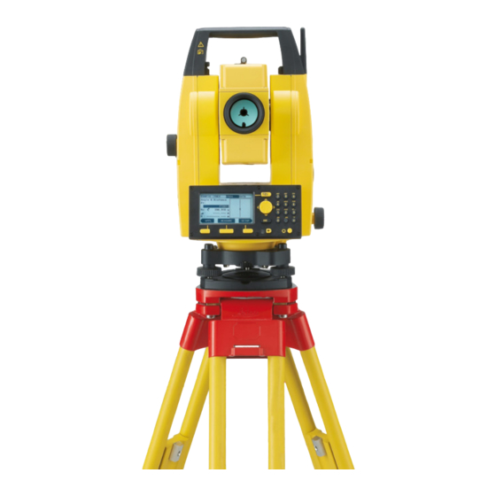
- Page 1 Leica Builder Series User Manual Version 1.0 English...
- Page 2 The type and the serial number of your product are indicated on the type plate. identification Enter the type and serial number in your manual and always refer to this information when you need to contact your agency or Leica Geosystems authorized service work- shop. Type: _______________ Serial No.:...
- Page 3 Symbols The symbols used in this manual have the following meanings: Type Description Danger Indicates an imminently hazardous situation which, if not avoided, will result in death or serious injury. Warning Indicates a potentially hazardous situation or an unintended use which, if not avoided, could result in death or serious injury.
-
Page 4: Table Of Contents
Builder, Table of Contents Table of Contents In this manual Chapter Page How to Use this Manual Technical Terms and Abbreviations Description of the System Instrument Models Container Contents Instrument Components Power Supply Software Concept User Interface Keyboard Screen Tab Bar Icons Symbols... - Page 5 Operation Selection of Language Instrument Setup Instrument Battery USB Memory Stick Distance Measurement 5.5.1 General 5.5.2 Measurement with Red Dot 5.5.3 Measurement with Prism CPR105 Flat Prism CPR111 Builder Prism, True-Zero Offset Configuration Mode Overview Accessing Communication Parameters How to Make a Setting Pin Assignment Builder, Table of Contents...
-
Page 6: Builder, Table Of Contents
Builder, Table of Contents Theodolite Mode Overview Accessing How to Set Horizontal Angle to 0.000 How to Set Any Horizontal Angle Quick Setting of Horizontal Angle and Vertical Angle Direction Measurement Program Mode, for Builder 200 or higher Overview Accessing Pointsearch Measure and Record... - Page 7 Station Setup, for Builder 200 or higher Overview Setup Option 1: Establish Control Line 9.2.1 General 9.2.2 Establish Control Line - Over 1 Point 9.2.3 Establish Control Line - Anywhere Setup Option 2: Establish Coordinates 9.3.1 General 9.3.2 Establish Coordinates - Over Known Point 9.3.3 Establish Coordinates - Anywhere Setup Option 3: Establish Height...
-
Page 8: Builder, Table Of Contents
Builder, Table of Contents 10 Application Programs, for Builder 200 or higher 10.1 Overview 10.2 Layout 10.3 As Built 10.4 Angle & Distance 10.5 Tie Distance 10.6 Area and Stockpile Volumes 10.6.1 Area Application 10.6.2 Stockpile Volumes Application 10.7 Hidden Point (optional) 10.8 COGO (optional) 10.9... - Page 9 12 EDM Settings 12.1 12.2 13 System Info and Instrument Protection 13.1 System Info 13.2 Instrument Protection (PIN) 13.3 Software Upload 13.4 Maintenance Key Upload 14 Check & Adjust 14.1 Overview 14.2 Preparation 14.3 Combined Adjustment of Hz Collimation (c), Vertical Index (i) and Compensator Index (l, t) Errors 14.4 Adjustment of the Circular Level...
-
Page 10: Builder, Table Of Contents
Builder, Table of Contents 15 Care and Transport 15.1 Transport 15.2 Storage 15.3 Cleaning and Drying 16 Construction Data Manager 16.1 Overview 16.2 Installation 16.3 Connection 16.4 Online help 17 Safety Directions 17.1 General 17.2 Intended Use 17.3 Limits of Use 17.4 Responsibilities 17.5... - Page 11 17.7 Electromagnetic Compatibility EMC 17.8 FCC Statement, Applicable in U.S. 18 Technical Data 18.1 Angle Measurement 18.2 Distance Measurement 18.3 General Technical Data of the Instrument 18.4 Conformity to National Regulations 18.4.1 Products without Communication side cover 18.4.2 Products with Communication side cover 19 International Limited Warranty, Software License Agreement Index Builder, Table of Contents...
-
Page 12: How To Use This Manual
Builder, How to Use this Manual How to Use this Manual It is recommended to set-up the instrument while reading through this manual. Index The index is at the back of the manual. Keys, fields and options on the screens which are considered as self-explanatory are not explained. - Page 13 Format of the The Builder CD contains the entire documentation in electronic format. It is also avail- documentation able in printed form. Builder, How to Use this Manual...
-
Page 14: Technical Terms And Abbreviations
Builder, Technical Terms and Abbreviations Technical Terms and Abbreviations Terminology... - Page 15 Term Description Line of sight / collimation axis Telescope axis = line from the reticle to the centre of the objective. Standing axis Vertical rotation axis of the instrument. Tilting axis Horizontal rotation axis of the telescope. Vertical angle / zenith angle Vertical circle With coded circular division for reading the vertical angle.
- Page 16 Builder, Technical Terms and Abbreviations Direction of gravity. The compensator defines the plumb Plumb line / line within the instrument Compensator Angle between plumb line and standing axis. Standing axis incli- Standing axis tilt is not an instrument error and is not nation eliminated by measuring in both faces.
- Page 17 Point on the plumb line above the observer. Zenith Glass plate within the telescope with reticle. Reticle Builder, Technical Terms and Abbreviations...
- Page 18 Builder, Technical Terms and Abbreviations Explanation of displayed data E, N, H...
- Page 19 Abbreviation Description Indicated meteorological corrected slope distance between instru- ment tilting axis and centre of prism/laser dot. Indicated meteorological corrected horizontal distance. Height difference between station and target point. Reflector height above ground. Instrument height above ground. Easting of Station. Northing of Station.
-
Page 20: Description Of The System
Builder, Description of the System Description of the System Instrument Models Instrument models Model Description Builder 100 Electronic theodolite. Builder 200 Electronic theodolite with distance measurement capability, RS232 interface and construction software. Builder 300 Same as Builder 200, additionally with internal memory to store and manage data, a USB mini and host interface and an extended application menu. -
Page 21: Container Contents
Container Contents Container contents, part 1 of 2 a) Builder instrument with supplied tribrach b) GEV189 USB data transfer cable* c) GLI115 clip-on bubble (for Builder 200 and 300) d) GHT196 holder for height meter* e) CPR105 Flat prism (for Builder 200 and 300) GHM007 height meter* g) Protective cover / lens hood... - Page 22 Adjustment tools k) GFZ3 diagonal eyepiece* GEB211 batteries m) GKL211 battery charger n) GAD105 Flat or mini prism adapter* o) MS1 Leica industrial grade USB memory stick (for Builder 300 or higher) p) GEB221 battery* q) Tip for mini prism pole...
-
Page 23: Instrument Components
Instrument Components Instrument compo- nents, part 1 of 2 a) Compartment for USB memory stick and USB cable ports (for Builder 300 or higher) b) Bluetooth antenna (only Builder 500) c) Alignment sight d) Detachable carrying handle with mounting screw e) Telescope (with integrated Distance Meter for Builder 200 or higher) Vertical drive... - Page 24 Builder, Description of the System Instrument compo- nents, part 2 of 2 k) Telescope focusing ring Eyepiece; focusing graticule m) Battery holder for GEB211/GEB221 n) Serial interface RS232 (for Builder 200 or higher) o) Footscrew p) Display q) Keyboard (Keyboard depends on model.
- Page 25 Communication The Communication side cover with USB is standard for Builder 300 or higher and in side cover case of the Builder 500 series additionally with Bluetooth. a) Bluetooth antenna (only Builder 500) b) Compartment lid c) USB memory stick cap storage d) USB host port e) USB device port Builder, Description of the System...
-
Page 26: Power Supply
External battery • One GEB171 battery connected via cable. Batteries a) GEB221 b) GEB211 Use the Leica Geosystems batteries, chargers and accessories or accessories recom- mended by Leica Geosystems to ensure the correct functionality of the instrument. -
Page 27: Software Concept
Software Concept Description All instrument types use the same software concept. The software has different modes depending on the instrument type. Software Concept Model Screen Available Modes Builder 100 • Configuration Mode • Theodolite Mode Builder 200 • Configuration Mode •... - Page 28 Builder, Description of the System Model Screen Available Modes Builder 300, 400 • Configuration Mode and 500 • Theodolite Mode • Programs Mode • Data Management Mode...
- Page 29 Builder, Description of the System...
-
Page 30: User Interface
Builder, User Interface User Interface Keyboard Builder 100, 200 and 300 Builder 400 and 500 Keyboard a) Page key a) Page key b) Navigation keys b) 10-digits keypad c) ESC c) Navigation keys d) Light d) ESC e) Function keys e) Light EDM key g) LED... - Page 31 Keys All Builder models: Description Changes tab in the tab bar. • Move the focus on the screen • Start the edit mode for edit fields • Control the input bar in edit and input mode • Leaves the current menu or dialog without storing changes made.
- Page 32 Builder, User Interface Only Builder 400 and 500: Key/LED Description • Press button short: to access the EDM settings • Press button long: to toggle between red dot and prism Alphanumeric keys _@& ± • LED white: EDM type is prism •...
- Page 33 Sidecover keys Description On / Off key. Switches the instrument on or off. Switch key. Switch Key 1 is the top end, Switch Key 2 is the lower end of the Switch key. Switch key functionality Builder model Switch key 1 Switch key 2 100 series Sector beep on/off...
-
Page 34: Screen
Builder, User Interface Screen All shown screens are examples. It is possible that local software versions are different to the basic version. Screen a) Tab bar b) Time c) Icons d) Screen area e) Softkeys... - Page 35 Description Element Description Tab bar The current active tab is shown black. Time Shows the current time provided that the setting is made in the configurations. Icons Shows the current status information of the instrument. Refer to "4.4 Icons". Screen area The working area of the screen.
-
Page 36: Tab Bar
Builder, User Interface Tab Bar Tab bar In the tab bar the current active software mode is shown black. <- Tab bar Mode CONFIG Configuration Mode THEO Theodolite Mode PROG Program Mode (for Builder 200 or higher) MODE Data Management Mode (for Builder 300 or higher) ... -
Page 37: Icons
Icons Description The icons provide information related to basic instrument functions. Battery The status and source of the battery is displayed. Icon Description Battery capacity The battery symbol indicates the level of the remaining battery capacity, 75% full shown in the example. Compensator Compensator on or off is displayed. -
Page 38: Symbols
Builder, User Interface Symbols Horizontal angle The direction of the horizontal angle is displayed. Symbol Description Indicates that horizontal angle is set to right side angle meas- urement (clockwise). Indicates that horizontal angle is set to left side angle measure- ment (anticlockwise). - Page 39 Distance Symbol Description This symbol indicates the horizontal distance. This symbol indicates the height difference. This symbol indicates the slope distance. Triangles Symbol Description Double triangles on the right indicate a choice field. A single triangle on the right indicates a choice list. Builder, User Interface...
-
Page 40: Operation
Builder, Operation Operation Selection of Language Description After switching on the instrument the user is able to choose his preferred language. The dialog to choose the language is only shown if two or more languages are loaded onto the instrument and <Lang.Dialog: On> is set in Configuration mode or on System Info dialog. - Page 41 Builder 200 connect the instrument to Construction Data Manager Version 6.0 or higher via the serial interface and load using Tools - Software Upload. Builder 100 contact your Leica Geosystems authorized service workshop. Builder, Operation...
-
Page 42: Instrument Setup
Builder, Operation Instrument Setup Description This topic describes an instrument setup over a marked ground point using the laser plummet. It is always possible to set up the instrument without the need for a marked ground point. Important features: •... - Page 43 Loosen the clamping screws on the tripod legs, pull out to the required length and tighten the clamps. In order to guarantee a firm foothold sufficiently press the tripod legs into the ground. When pressing the legs into the ground note that the force must be applied along the legs.
- Page 44 Builder, Operation Setup step-by-step 1. Extend the tripod legs to allow for a comfortable working posture. Position the tripod over the marked ground point, centring it as well as possible. 2. Fasten the tribrach and instrument onto the tripod. 3. Turn on the instrument by pressing the key.
- Page 45 5. Adjust the tripod legs (5) to level the circular level (7). 6. By using the electronic level turn the tribrach footscrews (6) to precisely level the instrument. Refer to "Levelling up with the electronic level step-by-step" for more informa- tion.
- Page 46 Builder, Operation 4. Centre the electronic level of this axis by turning the two footscrews. Arrows show the direction for rotating the footscrews. When the electronic level is centred the arrows are replaced by checkmarks. 5. Centre the electronic level for the second axis by turning the last footscrew.
- Page 47 Changing the External influences and the surface conditions may require the adjustment of the intensity of the intensity of the laser plummet. laser plummet 1. Turn on the instrument by pressing the key. The electronic level and laser plummet are activated automatically after switching on the instrument, if compensator is set to on.
- Page 48 Builder, Operation Under some circumstances the laser Positioning over dot is not visible, for example over pipes or holes pipes. In this case, the laser dot can be made visible by using a trans- parent plate so that the laser dot can be easily aligned to the center of the pipe.
-
Page 49: Instrument Battery
Instrument Battery 1. Open the battery compartment. Change instrument battery step-by- 2. Remove the battery holder. step 3. Remove the battery from the battery holder. 4. Insert the new battery into the battery holder, ensuring that the contacts are facing outward. The battery should click into position. - Page 50 +10°C to +20°C/+50°F to +68°F if possible. • It is normal for the battery to become warm during charging. Using the chargers recommended by Leica Geosystems, it is not possible to charge the battery if the temperature is too high. •...
- Page 51 Inserting and removing the batteries Warning Batteries not recommended by Leica Geosystems may be damaged if charged or discharged. They may burn and explode. Precautions: Only charge and discharge batteries recommended by Leica Geosystems.
-
Page 52: Usb Memory Stick
3. Insert the USB memory stick into the USB host port. 4. The cap of a Leica industrial grade USB memory stick can be stored on the underside of the compartment lid. 5. Close the compartment lid and turn the knob to lock the... - Page 53 Whilst other USB memory sticks may be used, Leica Geosystems recommends Leica industrial grade USB memory sticks and cannot be held responsible for data loss or any other error that may occur when using a non-Leica USB memory stick. ...
-
Page 54: Distance Measurement
A laser distancer (EDM) is incorporated into the instruments (Builder 200 or higher) of the Builder series. In all these versions, the distance can be determined by using a visible red laser beam which emerges coaxially from the telescope objective. -
Page 55: Measurement With Red Dot
5.5.2 Measurement with Red Dot Description • When measurements are being made using the red laser EDM, the results may be influenced by objects passing between the EDM and the intended target surface. This occurs because red dot measurements are made to the first surface returning sufficient energy to allow the measurement to take place. - Page 56 Builder, Operation example a passing vehicle, heavy rain, fog or snow is between the instrument and the point to be measured, the EDM may measure to the obstruction. • Be sure that the laser beam is not reflected by anything close to the line of sight, for example highly reflective objects.
-
Page 57: Measurement With Prism
5.5.3 Measurement with Prism Description • Accurate measurements to prisms should be made with the standard program (EDM type: prism). • Measurements to strongly reflecting targets such as to traffic lights in reflector EDM mode without prism should be avoided. The measured distances may be wrong or inaccurate. -
Page 58: Cpr105 Flat Prism
Builder, Operation CPR105 Flat Prism Descprition The standard supplied Flat Prism (delivered with Builder 200 and 300) has two different reflective surfaces. The highly reflective cat-eye surface can be used for measurements up to 250 m. The reflective tape has printed crosshairs for precise aiming at close range. -
Page 59: Cpr111 Builder Prism, True-Zero Offset
CPR111 Builder Prism, True-Zero Offset Description This prism with true-zero offset is only delivered with the Builder 400 and 500. The closer the prism is mounted to the ground, the more accurate it can be positioned over the measured point. For more precise positioning at higher prism positions, the GLS111 reflector pole with GAD105 adapter is recommended. -
Page 60: Configuration Mode
Builder, Configuration Mode Configuration Mode Overview Description The CONFIG mode is used for: • creating user specific settings in order to adapt the instrument to your own requirements. • setting date and time. • setting units. • setting communication parameters. ... -
Page 61: Accessing
Accessing Access step-by- Step Description step Turn on the instrument by pressing the key. Level up the instrument. Refer to "5.2 Instrument Setup" for more infor- mation. Press until CONFIG mode is active. Example of a configuration screen DISP To set configurations regarding display. - Page 62 Builder, Configuration Mode Description of fields for main configuration screen Field Option Description <Laser Turns off the visible laser beam. Pointer:> Turns on the visible laser beam. (only Builder 200, 300 and 500) <Tracking:> Turns off continuous distance measure mode. (Builder 200 Turns on continuous distance measure mode.
- Page 63 Field Option Description <V Setting:> Sets the vertical angle. Zenith Zenith=0°; Horizon=90° Horizon Zenith=90°; Horizon=0° Vertical angles are positive above the horizon and negative below it. Builder, Configuration Mode...
- Page 64 Builder, Configuration Mode Field Option Description V(%) Vertical angles are expressed Slope % +300 % in % with positive above the --.--% +100% horizon and negative below +18 % 100% corresponds to an 360s vertical angle of 45° (50 gon, 0°...
- Page 65 Field Option Description Turns off the compensator. Vertical angles are relative to vertical/standing axis. If the instrument is used on an unstable base, for example shaking platform, ship, etc. the compensator should be switched off. This avoids the compensator drifting out of its measuring range and interrupting the measuring process by indicating an error.
- Page 66 Builder, Configuration Mode Field Option Description The key beep is an acoustic signal after each keystroke. The sector beep is an acoustic signal which sounds if horizontal angle is 0°, 90°, 180°, 270° or 0, 100, 200, 300 gon. The sector beep is useful for staking out right angles.
- Page 67 Field Option Description No beep Fast beep, interrupted; from 95.0 to 99.5 gon and 105.0 to 100.5 gon Permanent beep; from 99.5 to 99.995 gon and from 100.5 to 100.005 gon <Auto Off:> Sets the behaviour of power down and instrument. Enable The instrument is turned off after 20 minutes without any action, for example no key pressed;...
- Page 68 Builder, Configuration Mode Field Option Description MEASURE Starts distance and angle measurements without saving measured values in certain applications. It is not possible to save any values. Description of fields for display configuration screen Field Option Description <Contrast:> From 10% to Adjusts the contrast level for the display immedi- 100% ately.
- Page 69 Field Option Description Dec.deg Degree decimal: possible angle values: 0° to 359.999° Gon: possible angle values: 0 gon to 399.999 gon Mil: possible angle values: 0 to 6399.99mil The setting of the angle units can be changed at any time. The actual displayed values are converted according to the selected unit.
- Page 70 Builder, Configuration Mode Field Option Description Standard or 0° 00' 05" for <Angle Unit: ° ' ''>. Precise (only 0.001 for <Angle Unit: Gon> and <Angle Unit: 9" models) Dec.deg>. 0.05 for <Angle Unit: Mil>. Simple or 0° 00' 10" for <Angle Unit: ° ' ''>. Standard (only 0.005 for <Angle Unit: Gon>...
- Page 71 Field Option Description <Lang. If two or more languages are loaded onto the Dialog:> instrument, a dialog to choose the language can be shown directly after switching on the instrument. The language dialog is shown as startup dialog. The language dialog is not shown as startup dialog. Description of fields for time configuration screen Field Option...
-
Page 72: Communication Parameters
Builder, Configuration Mode Communication Parameters Description Data can be stored in internal memory or to an external device such as PDA, Data Collector or PC through the RS232 interface, the mini USB port or via Bluetooth. The available options depend on the Builder model. For data transfer between instrument and an external device the communication parameters of the intended communication type must be set. - Page 73 Field Option Description Data Output RS232 Data is recorded via the serial interface. For this purpose, a data storage device must be connected to the serial interface. Int. Mem. All data is recorded in the internal memory. Data is recorded via the mini USB interface. For this purpose, a data storage device must be connected to the mini USB port (for Builder 300 or higher).
- Page 74 Builder, Configuration Mode Field Option Description Databits Number of bits in a block of digital data. Set automatically if <Parity:> Even or Odd. Set automatically if <Parity:> None. Parity None, Even or Error checksum at the end of a block of digital data.
- Page 75 Field Option Databits Parity None Endmark CR/LF Stopbits Set communication 1. Make sure that CONFIG Mode is active. parameters step- 2. Press COM to access communication parameter setting. by-step 3. Press to set focus on desired field. 4. Press to toggle through the settings and select desired field. 5.
-
Page 76: How To Make A Setting
Builder, Configuration Mode How to Make a Setting How to make a 1. Make sure that CONFIG Mode is active. setting with a 2. Press to set focus on desired field. choicelist step-by- step 3. Press to access the choicelist. 4. -
Page 77: Pin Assignment
Pin Assignment Port at the instru- Diagram Name Description Direction ment PWR_IN Power input: + 12 V nominal (11 - 16 V) Not used Single ground RS232, receive RS232, transmit b c d Builder, Configuration Mode... -
Page 78: Theodolite Mode
Builder, Theodolite Mode Theodolite Mode Overview Description The THEO mode is used for: • levelling up the instrument with the electronic level and adjusting the intensity of the laser plummet • reading off the current horizontal and vertical angle • setting horizontal angle to zero •... -
Page 79: Accessing
Accessing Access step-by- 1. Turn on the instrument by pressing the key. step 2. Level up the instrument. Refer to "5.2 Instrument Setup" for more information. 3. Press until THEO mode is active. Example of a theodolite screen Hz HOLD To set any horizontal angle. - Page 80 Builder, Theodolite Mode Field Description Thanks to dual axis compensation, the Builder is able to adjust the horizontal angle reading accordingly. Therefore, turning the telescope vertically might cause the horizontal angle to change. The change in <Hz:> is the compensation of the standing axis tilt.
-
Page 81: How To Set Horizontal Angle To 0.000
How to Set Horizontal Angle to 0.000 Set horizontal 1. Make sure that THEO Mode is active. angle to 0.000 2. Turn telescope and aim at desired target point. step-by-step 3. Press Hz = 0. 4. Accept with OK. The horizontal angle is set to 0.000. Builder, Theodolite Mode... -
Page 82: How To Set Any Horizontal Angle
Builder, Theodolite Mode How to Set Any Horizontal Angle Set any horizontal 1. Make sure that THEO Mode is active. angle step-by-step 2. Turn telescope to desired horizontal angle. 3. Press Hz hold. 4. Turn telescope and aim at a target point. 5. -
Page 83: Quick Setting Of Horizontal Angle And Vertical Angle Direction Measurement
Quick Setting of Horizontal Angle and Vertical Angle Direc- tion Measurement Quick setting of 1. Make sure that THEO Mode is active. horizontal angle 2. Press to set horizontal angle to "clockwise direction measurement" or direction measure- press to set horizontal angle to "counter-clockwise direction measurement". ment step-by-step The horizontal angle is set to clockwise direction or counter-clockwise direction measurement. -
Page 84: Program Mode, For Builder 200 Or Higher
Builder, Program Mode, for Builder 200 or higher Program Mode, for Builder 200 or higher Overview Description The PROG mode is used for: • distance measurements • Station Setup • working with application programs Descriptions apply to Builder 200 or higher. Available options depend on the model. -
Page 85: Accessing
Accessing Access step-by- 1. Turn on the instrument by pressing the key. step 2. Level up the instrument. Refer to "5.2 Instrument Setup" for more information. 3. Press until PROG mode is active. APPL To start application programs Example of an menu. -
Page 86: Pointsearch
Builder, Program Mode, for Builder 200 or higher Pointsearch Description Pointsearch is a global function used by applications and setups, for example to find internally saved measured or fixed points. Descriptions apply to Builder 300 or higher. Available options depend on the model. Pointsearch step- 1. - Page 87 Example of a Pointsearch screen DELETE To remove the last character. To access the point list. ABC1 To switch between numeric and alphanumeric input. Field Description <Search ID:> Enter the point to be searched for. The middle data point matches the entered information best. Wildcard search Instead of a certain Point ID a wildcard represented by a * can be used as Search ID.
-
Page 88: Measure And Record
Builder, Program Mode, for Builder 200 or higher Measure and Record Possibilities The Measure and Record function can be used in three different ways: • Measure and record in one step (ALL-in-1) • Combining the functions MEASURE and RECORD • Using MEASURE only Measure and 1. - Page 89 Combining The key combination of MEASURE and RECORD can be used to measure non acces- MEASURE and sible points with the prism, for example building corners. RECORD step-by- step 1. Make sure that PROG Mode is active. 2. Make sure that <Measure&Record: MEAS/REC> is set. Refer to "6 Configuration Mode"...
- Page 90 Builder, Program Mode, for Builder 200 or higher MEASURE only 1. Make sure that PROG Mode is active. step-by-step 2. Make sure that <Measure&Record: MEASURE> is set. Refer to "6 Configuration Mode" for information on how to make the setting. 3.
- Page 91 Builder, Program Mode, for Builder 200 or higher...
-
Page 92: Station Setup, For Builder 200 Or Higher
Builder, Station Setup, for Builder 200 or higher Station Setup, for Builder 200 or higher Overview Description The Setup programs can be used to set up and orientate the instrument. Three Setup options with different Setup methods are available: • Control line •... - Page 93 Setup Option Setup Method Description Height Height Transfer To determine the height of the position of the instrument from measurements to up to five target points with known height. For the different Setup methods, different types of data and a different number of control points have to be available.
-
Page 94: Setup Option 1: Establish Control Line
Builder, Station Setup, for Builder 200 or higher Setup Option 1: Establish Control Line 9.2.1 General Description The Setup Option Control Line is used to set up the instrument in relation to a control line. All further measuring points and points to be staked are in relation to the control line. -
Page 95: Establish Control Line - Over 1
9.2.2 Establish Control Line - Over 1 Point Description The Setup method Control Line - Over 1 Point is used to set the station coordi- nates to E = 0.000, N =0.000, H =0.000 and the orientation to 0.000. Diagram Hz = 0.000 Station Target point... -
Page 96: Establish Control Line - Anywhere
Builder, Station Setup, for Builder 200 or higher 9.2.3 Establish Control Line - Anywhere Description The Setup method Establish Control Line - Anywhere is used to set up the instru- ment along a control line. The coordinates of line start point are set to E = 0.000, =0.000 and H =0.000. - Page 97 Shifting Line Start- In Setup method Establish Control line - Anywhere line startpoint can be shifted point to use another origin for the local coordinate system. If the entered line value is posi- tive the start point moves forward otherwise backward. The start point gets a right- ward shift if the entered offset value is positive otherwise a leftward shift.
- Page 98 Builder, Station Setup, for Builder 200 or higher Example of a dialog for shifting line startpoint Set=0 To set line or offset values to zero. To accept entered/measured line or offset values. MEAS To measure new origin of local coordinate system.
-
Page 99: Setup Option 2: Establish Coordinates
Setup Option 2: Establish Coordinates 9.3.1 General Description The Setup Option Coordinates is used to set up the instrument in relation to a local or global coordinate system. All further measuring points and points to be staked are in relation to the coordinate system. Builder, Station Setup, for Builder 200 or higher... -
Page 100: Establish Coordinates - Over Known Point
Builder, Station Setup, for Builder 200 or higher 9.3.2 Establish Coordinates - Over Known Point Description The Setup method Establish Coordinates - Over Known Point is used to set up the instrument on a known point and orient to a known azimuth or to up to five known backsight points. - Page 101 Example of a result screen REDO To delete or re-measure a used backsight point. To accept computed/measured values. Builder, Station Setup, for Builder 200 or higher...
-
Page 102: Establish Coordinates - Anywhere
Builder, Station Setup, for Builder 200 or higher 9.3.3 Establish Coordinates - Anywhere Description The Setup method Establish Coordinates - Anywhere is used to set up the instru- ment on an unknown point and set the orientation by measuring angles and distances to a minimum of two known target points and a maximum of five target points. - Page 103 Example of a result screen REDO To delete or re-measure a used target point. To accept computed/measured values. To switch to height result screen. Builder, Station Setup, for Builder 200 or higher...
-
Page 104: Setup Option 3: Establish Height
Builder, Station Setup, for Builder 200 or higher Setup Option 3: Establish Height 9.4.1 General Description The Setup Option Establish Height is used to enter the station height, instrument height and reflector height. All further measuring points and points to be staked are in relation to the entered values. -
Page 105: Height Transfer
9.4.2 Height Transfer Description The Setup method Height Transfer is used to determine the height of the position of the instrument from measurements to up to five target points with known height. Diagram Station First point with known height Second point with known height Third point with known height Example of a result screen... -
Page 106: Application Programs, For Builder 200 Or Higher
Builder, Application Programs, for Builder 200 or higher Application Programs, for Builder 200 or higher 10.1 Overview Description Application programs are predefined programs, that cover a wide spectrum of construction tasks and facilitate daily work in the field. Up to nine different applica- tion programs are available. - Page 107 Application program Description Hidden Point To measure points that are not directly visible. Two methods: using a rod with two targets, alternatively enter line of sight shift and/or side shift manually. COGO Performs coordinate geometry calculations such as inter- sections and more. Layout Line/Arc/Spiral Layout and as-built check of lines, arcs or spirals.
-
Page 108: Layout
Builder, Application Programs, for Builder 200 or higher 10.2 Layout Description The application program Layout is used to place markers in the field at predeter- mined points. These predetermined points are the points to be staked. The points to be staked are defined by entering line and offset or easting, northing and height depending on the used setup method. - Page 109 Example of a layout APPL To start application application screen programs menu. MEASURE To measure and display stake out differences. To turn on/off Tracking mode by pressing for approximately 5 seconds. SETUP To start station setup menu. Field Description <Pt:> The identifier for the points to be staked.
- Page 110 Builder, Application Programs, for Builder 200 or higher Field Description <E:> Available if a Setup method with Coordinates was used. Easting of point to be staked. <N:> Available if a Setup method with Coordinates was used. Northing of point to be staked. <H:>...
-
Page 111: As Built
10.3 As Built Description The application program As built is used for measuring an unlimited number of points. The program shows line and offset values or easting, northing and height depending on the used Setup method. Displayed graphic and available values depend on the used Setup method. Example of an As Built application screen... - Page 112 Builder, Application Programs, for Builder 200 or higher Field Description <Line:> Available if a Setup method with Control Line was used. Longitudinal offset of the start point of the control line in the direc- tion of the second point of the control line. Line is positive in the direction from line start point to second line point.
- Page 113 Diagram Station Line start point Second line point Measured point Line Offset Elements of the In application program As Built a graphical display shows the position of the station, graphical display used control points, the reflector and the last 50 measured points. Element Description Element...
-
Page 114: Angle & Distance
Builder, Application Programs, for Builder 200 or higher 10.4 Angle & Distance Description The application program Angle & Distance is used for measuring an unlimited number of points. The program shows horizontal angle, horizontal distance and height. Displayed graphic and available values depend on the used Setup method. Example of an Angle &... - Page 115 Field Description <Hz:> The current horizontal angle. The measured horizontal distance to the target point. <H:> Height of measured point. Elements of the Refer to "10.3 As Built" for more information. graphical display Builder, Application Programs, for Builder 200 or higher...
-
Page 116: Tie Distance
Builder, Application Programs, for Builder 200 or higher 10.5 Tie Distance Description The application program Tie Distance is used to compute horizontal distance, height difference and grade between two target points. The target points have to be meas- ured. The user can choose between two different methods: •... - Page 117 Diagram Radial (P1-P2, P1-P3) Station Target point Target point Target point Target point Distance between P1 and P2 Distance between P1 and P3 Distance between P1 and P4 Example of a Tie Distance result screen To measure more points. Builder, Application Programs, for Builder 200 or higher...
- Page 118 Builder, Application Programs, for Builder 200 or higher Field Description <From:> The identifier for the first measured point. Available for Builder 300 or higher. <To:> The identifier for the second measured point. Available for Builder 300 or higher. Calculated horizontal distance between the measured points. Calculated height difference between the measured points.
-
Page 119: Area And Stockpile Volumes
10.6 Area and Stockpile Volumes Description The application program Area with methods 'plane' and 'tilt' is used to compute area size of areas with max. 50 boundary points connected by straights. Furthermore a volume with constant height can be calculated. The calculated area is projected onto the horizontal plane or projected onto the tilted reference plane depending on the chosen method. -
Page 120: Area Application
Builder, Application Programs, for Builder 200 or higher 10.6.1 Area Application Description The boundary points have to be measured ordered, either in clockwise or anticlock- wise direction. Station Start point Target point Target point Target point The area is calculated and displayed once three points have been measured. - Page 121 Example of an Area Result screen To measure more points. VOLUME To calculate a volume with constant height. Field Description <NoPt:> Number of measured points. <Area:> Calculated area. <Peri:> Calculated perimeter. Builder, Application Programs, for Builder 200 or higher...
- Page 122 Builder, Application Programs, for Builder 200 or higher Station Diagram: Area Start Point application Target Point Target Point Target Point Constant height Perimeter (tilt) of the tilted area stretched by all current measured points Area (tilt), always closed to the start point P1 projected, onto the tilted reference plane Volume (tilt) = c x a...
-
Page 123: Stockpile Volumes Application
10.6.2 Stockpile Volumes Application Description The points of the first (outer) boundary have to be measured ordered, either in clock- wise or anticlockwise direction. The same is for the second (inner) boundary. To measure more points. BREAKL. To start measuring the second (inner) boundary. -
Page 124: Hidden Point (Optional)
Builder, Application Programs, for Builder 200 or higher 10.7 Hidden Point (optional) Description The application program Hidden Point allows measurements to a point that is not directly visible. The point can be determined by a rod or by entering the shift in the line of sight and the side shift. - Page 125 Diagram Rod a) Hidden Point b) Rod length c) First reflector d) Second reflector Diagram Shift (Example) Station Reflector Hidden point Line of sight Side shift Builder, Application Programs, for Builder 200 or higher...
- Page 126 Builder, Application Programs, for Builder 200 or higher Example of Hidden Point result screen To measure next hidden point. Field Description <RL=Rod Length:> Length of used rod. <Line of sight:> Longitudinal offset from reflector in direction to the instru- ment. <Side shift:>...
- Page 127 Elements of the In application program Hidden Point a graphical display shows the position of the graphical display station, the reflector and the hidden point. Element Description Station Line instrument-reflector Reflector/first measured target of the rod Hidden point North Control Line Builder, Application Programs, for Builder 200 or higher...
-
Page 128: Cogo (Optional)
Builder, Application Programs, for Builder 200 or higher 10.8 COGO (optional) Description The application program COGO is an application program to perform coordinate geometry calculations such as: • Coordinates of points • Directions between points • Distances between points The COGO calculation methods are: •... - Page 129 Diagram Intersec- Two Distances tions Known First known point Second known point Radius, as defined by the distance from P1 to P3 or P4 Radius, as defined by the distance from P2 to P3 or P4 Unknown First COGO point Second COGO point Direction&Distance Known...
- Page 130 Builder, Application Programs, for Builder 200 or higher Two Lines Known First known point of line 1 Second known point of line 1 First known point of line 2 Second known point of line 2 Line 1 Line 2 Unknown COGO point Two Directions Known...
- Page 131 Diagram Line The Extension routine computes extended point from base line. Extension Known Baseline start point Baseline end point ΔL Distance from end point Unknown Extended point Builder, Application Programs, for Builder 200 or higher...
- Page 132 Builder, Application Programs, for Builder 200 or higher Diagram Offset Line Offset Line & Plane Known Baseline start point Baseline end point Offset point Unknown Base point Line Offset Plane Offset Known Point 1 which defines plane Point 2 which defines plane Point 3 which defines plane Offset point Unknown...
- Page 133 Set Point by Offset Known Baseline start point Baseline end point Line Offset Unknown Offset point Diagram Inverse & Inverse Traverse Known First known point Second known point Unknown Horizontal distance between P1 and Height difference between P1 and α Direction from P1 to P2 Builder, Application Programs, for Builder 200 or higher...
- Page 134 Builder, Application Programs, for Builder 200 or higher Traverse Known Known point α Direction from P1 to P2 Horizontal distance between P1 and Positive offset to the right Negative offset to the left Unknown COGO point without offset COGO point with positive offset COGO point with negative offset Example of a COGO Result screen...
- Page 135 Refer also to the applications before. Field Description <Direction:> Direction between two points. <Dist.:> Distance between two points. <Line:> Longitudinal offset from the start point of the baseline. <Offset:> Cross offset to the baseline. Calculated horizontal distance between two points. Calculated height difference between two points.
- Page 136 Builder, Application Programs, for Builder 200 or higher Elements of the In application program COGO a graphical display shows the position of the station, graphical display used known points, directions, distances and the new calculated point. Element Description Station Direction between two points Distance between two points Distance and direction between two points Known point...
-
Page 137: Layout Line/Arc/Spiral (Optional)
10.9 Layout Line/Arc/Spiral (optional) Description The application program Layout Line/Arc/Spiral facilitates the easy stake out or checking of lines, grids, arcs, segments and spirals. Besides the usual layout of these elements, this application allows the user to stake out and check points relative to a road alignment. - Page 138 Builder, Application Programs, for Builder 200 or higher Start point of arc Diagram Arc End point of arc Center point of circle Radius of arc Direction Line Offset Point to stake or check Arc-turn clockwise ACW Arc-turn anticlockwise...
- Page 139 Diagram Spiral A = R x L Start point of spiral End point of spiral Radius Length Spiral parameter Spiral-turn clockwise ACW Spiral-turn anticlockwise Point to stake or check Line Offset Spiral direction (in, out) Builder, Application Programs, for Builder 200 or higher...
- Page 140 Builder, Application Programs, for Builder 200 or higher Diagram Road d = 155.000 Line d = 132.000 Spiral d = 122.000 Radius Offset left d = 112.000 Offset right Interval Defined chainage d = 102.000 It’s only possible to work with one element (Line or Arc or Spiral).
- Page 141 Example of Layout Line/Arc/Spiral APPL To start application result screen programs menu. M & R To measure and display distances and record data. To turn on /off laser pointer by pressing for approxi- mately 5 seconds (except Builder 400). Field Description <Chai:>...
- Page 142 Builder, Application Programs, for Builder 200 or higher Elements of the In application program Layout Line/Arc/Spiral a graphical display shows the position graphical display of the station, reference element with its definitions, the reflector and the last 50 measured points. Element Description Element...
-
Page 143: Measure & Descriptor
10.10 Measure & Descriptor Description In the program Measure & Descriptor it is possible to give each measured point a descriptor. Further it shows slope and horizontal distances and height differences. The application program Measure & Descriptor is only available for the Builder 400 and 500. - Page 144 Builder, Application Programs, for Builder 200 or higher Field Description The measured slope distance to the target point. The horizontal distance to the target point. The height difference to the target point.
- Page 145 Builder, Application Programs, for Builder 200 or higher...
-
Page 146: Data Management Mode, For Builder 300 Or Higher
Builder, Data Management Mode, for Builder 300 or higher Data Management Mode, for Builder 300 or higher 11.1 Overview Description The DATA mode is used for: • creating, viewing and deleting data in the field • data exchange with the USB memory stick ... -
Page 147: Accessing
11.2 Accessing Access step-by- 1. Turn on the instrument by pressing the key. step 2. Level up the instrument. Refer to "5.2 Instrument Setup" for more information. 3. Press until DATA mode is active. Example of a data management screen IMP/EXP To import data from or export field data to USB... - Page 148 Builder, Data Management Mode, for Builder 300 or higher Field Description <E:> Easting coordinate. <N:> Northing coordinate. <H:> Height.
-
Page 149: Jobs
11.3 Jobs Description Jobs are a summary of different types of data, for example fixpoints, measurements, result, etc. The job definition consists of the input of job name, operator and remark. Additionally, the system generates time and date at the time of creation. Active job The active job is the one in which data is stored to. - Page 150 Builder, Data Management Mode, for Builder 300 or higher View and select a 1. Make sure that DATA Mode is active. job step-by-step 2. Press JOB to access job management. 3. Press to toggle through the jobs and select job. 4.
-
Page 151: Fixpoints
11.4 Fixpoints Description Fixpoints contain at least a point identifier, easting and northing or height. Fixpoints can be • created, viewed and deleted in the field. • downloaded for data transfer to a further program. • uploaded, for example for stakeout operations. Create a new 1. - Page 152 Builder, Data Management Mode, for Builder 300 or higher View a fixpoint 1. Make sure that DATA Mode is active. step-by-step 2. Press to set <Type:> Fixpoint. to set focus on <Pt:>. 3. Press 4. Press to toggle through the points. The coordinates are displayed on same screen.
-
Page 153: Measurements
11.5 Measurements Description Measurement data contains at least horizontal angle, vertical angle, horizontal distance, slope distance, height difference, data, time and if applicable, line, offset, easting, northing and height coordinates. Measurement data can be: • viewed • deleted • downloaded for data transfer to a further program View a measure- 1. - Page 154 Builder, Data Management Mode, for Builder 300 or higher Delete a measure- 1. Make sure that DATA Mode is active. ment step-by-step 2. Press to set <Type:> Measurement. to set focus on <Pt:>. 3. Press 4. Press to toggle through the points and select point. 5.
-
Page 155: Result
11.6 Result Description Result data contains a result identifier and the different values depending on the application. The applications from which these result data can be displayed are Area and Tie Distance. Result data can be: • viewed • downloaded for data transfer to a further program View a result step- 1. -
Page 156: Data Transfer
For data transfer use: • Construction Data Manager Simple office software which supports the exchange of Leica TPS data with the PC via cable, USB memory stick or Bluetooth, using a Windows® application. 11.7.1 USB Memory Stick - Import / Export... - Page 157 Example of an export screen To accept settings. Field Option Description <Exchange Export Export screen is set as default. mode:> Import To switch to Import screen. <Data Measurements Only measurements will be exported. Type:> Meas.&Fixpoints Measurements and Fixpoints will be exported.
- Page 158 Builder, Data Management Mode, for Builder 300 or higher The name of the resulting GSI file is automatically created accordingly to the name of the selected job! The file is stored in the Data folder on the USB memory stick! Example of an Import screen To accept settings.
- Page 159 The GSI file for Import has to be stored into the Data folder on the USB memory stick! It is automatically detected and provided in the selection list! Builder, Data Management Mode, for Builder 300 or higher...
-
Page 160: Edm Settings
Builder, EDM Settings EDM Settings 12.1 Description With the instrument different settings are available for measurements with red dot (without reflectors) and prism (with reflectors). The LED on the keyboard indicates the selected type. Depending on the selected type the selection of prism types is different. - Page 161 Example of EDM settings screen To accept settings. RANGE To disable limited distance measurement. Button disappears when entered once. Field Option Description <EDM Type:> prism Fine measuring type for high precision measure- ments with prisms. red dot For distance measurements without prisms. <Laser Pointer>...
- Page 162 Field Option Description <Prism Type:> TrueZero CPR111 Builder Prism, True-Zero Offset JpMini Sliding Mini Prism Mini Leica Mini Prism Round Standard Leica Prism Flat Prism CPR105 Flat Prism Tape Reflective Tape User User can define his own prism. <Prism Const.:>...
-
Page 163: Ppm
12.2 Description This option enables the entry of a scale factor. Measured values and coordinates are corrected with the PPM parameter. Descriptions apply only to Builder 400 and 500. Access step-by- 1. Make sure that EDM Settings is active. step 2. - Page 164 Builder, EDM Settings Example of PPM screen PPM=0 To set PPM parameter to zero. To accept parameter Field Description <Scale factor:> Calculated scale factor. <Scale ppm:> Entry of PPM value to calculate scale factor.
- Page 165 Atmospheric Atmospheric correction in ppm with °C, mb, H (metres) at 60% relative humidity correction °C 550 mb 1000 1050 mb 50°C 50°C 40°C 40°C 30°C 30°C 20°C 20°C 10°C 10°C 0°C 0°C -10°C -10°C -20°C -20°C 550 mb 1000 1050 mb 5000 m 4500 4000 3500...
- Page 166 Builder, EDM Settings Atmospheric Atmospheric correction in ppm with °F, inch Hg, H (feet) at 60% relative humidity correction °F 16 17 18 19 20 21 22 23 24 25 26 27 28 29 30 31 32 inch Hg 130°F 130°F 120°F 120°F...
- Page 167 Builder, EDM Settings...
-
Page 168: System Info And Instrument Protection
Builder, System Info and Instrument Protection System Info and Instrument Protection 13.1 System Info Description The System Info is used for: • checking system and software information • performing the calibrations of the instrument errors Descriptions apply in general to all Builder models. Available options depend on the model. - Page 169 Example of a system info screen CALIBR To access the calibration routine. Refer to chapter "14 Check & Adjust". To access PIN code settings. SW Info To access software infor- mation. Field Description <Battery:> Remaining battery power (for example 80%). <Instr.Temp.:>...
- Page 170 Builder, System Info and Instrument Protection Field Description <Instr.Type:> An alternative instrument type can be selected to reduce the software functionality, for example for demonstration purpose. For Builder 500 the instrument type 400, 300, 200 and 100 may be chosen as an alternative. For Builder 400 the instrument type 100 may be chosen as an alternative.
-
Page 171: Instrument Protection (Pin)
13.2 Instrument Protection (PIN) Description The instrument can be protected by a Personal Identification Number. If the PIN protection is activated, the instrument will always prompt for a PIN code entry after starting up. As soon as the PIN was activated the access to the PIN code settings requires the PIN. - Page 172 Builder, System Info and Instrument Protection Deactivate PIN 1. Turn on the instrument by pressing the key. code step-by-step 2. Make sure that THEO mode is active. 3. Press for approximately 5 seconds. 4. Enter your personal PIN in <PIN-CODE>:. 5.
- Page 173 Field Option Description <Use PIN-Code:> To activate PIN-code. To deactivate PIN-code. <New PIN-Code:> To enter your personal PIN-code (max. 6 char- acter numeric). Builder, System Info and Instrument Protection...
-
Page 174: Software Upload
Description To load the application software or an additional language, connect the instrument to Leica’s Construction Data Manager via the serial interface or USB cable and load using Tools - Software Upload. Refer to the Construction Data Manager help for further information. - Page 175 Loading firmware 1. To load firmware and languages: Select Firmware & Language. and languages The Select File screen will appear. step-by-step To load only languages: Select Languages and skip to step 4. 2. Select the firmware file from the System folder on the USB memory stick. All firmware and language files must be stored in the System folder to be trans- ferred to the instrument.
-
Page 176: Maintenance Key Upload
Builder, System Info and Instrument Protection 13.4 Maintenance Key Upload Description To fully activate hardware functionality, onboard applications and maintenance contracts, licence keys may be required on the instrument. For all instruments, licence keys can be manually entered or up-loaded via Construction Data Manager. For instruments fitted with a Communication side cover licence keys can also be uploaded via a USB memory stick. - Page 177 Builder, System Info and Instrument Protection...
-
Page 178: Check & Adjust
14.1 Overview Description Leica instruments are manufactured, assembled and adjusted to the best possible quality. Quick temperature changes, shock or stress can cause deviations and decrease the instrument accuracy. It is therefore recommended to check and adjust the instrument from time to time. - Page 179 • Laser plummet • Screws on tripod • Visible red laser beam for Builder 200 or higher. Only Leica Geosystems author- ized service workshops are entitled to adjust these products. • Vertical line of the reticule for Builder 100. ...
-
Page 180: Preparation
Builder, Check & Adjust 14.2 Preparation Before determining the instrument errors, the instrument has to be levelled-up using the electronic level. The tribrach, the tripod and the underground should be very stable and secure from vibrations or other disturbances. ... -
Page 181: Combined Adjustment Of Hz Collimation (C), Vertical Index (I) And Compensator Index (L, T) Errors
14.3 Combined Adjustment of Hz Collimation (c), Vertical Index (i) and Compensator Index (l, t) Errors Description The combined adjustment procedure determines the following instrument errors in one process: Type Description Diagram The Hz collimation error (c) is also called line of sight error. It is caused by the deviation between the optical line of sight, which means the direction in which the... - Page 182 Builder, Check & Adjust Type Description Diagram A vertical index error (i) exists, if the 0° mark of the vertical circle reading doesn't coincide with the mechanical vertical axis of the instrument, also called standing axis. The vertical index error (i) is a constant error that affects all vertical angle read- ings.
- Page 183 Combined adjust- The following table explains the most common settings. Refer to the stated chapter ment procedure for more information on screens. step-by-step 1. Turn on the instrument by pressing the key. 2. Level up the instrument. Refer to "5.2 Instrument Setup" for more information. 3.
- Page 184 Builder, Check & Adjust Aim with the telescope accurately at a target at a distance of about 100 m. The target must be positioned within ± 5° of the 180° horizontal plane. 180° 10. Press MEASURE to measure the same target again and to calculate the instru- ment errors.
- Page 185 Set Hz correction Field Option Field Description <Hz-Correction:> The horizontal angles are corrected for the line of sight and if <Compensator: On> transversal tilt errors. Horizontal angles are not corrected. After switching on the instrument, the setting is automatically reset to <Hz- Correction: On >.
-
Page 186: Adjustment Of The Circular Level
Builder, Check & Adjust 14.4 Adjustment of the Circular Level On the instrument step-by-step 1. Level up the instrument in advance with the electronic level, assuming that the electronic level is correctly adjusted. 2. The bubble must be centered. If it extends beyond the circle, use the allen keys supplied to centre it with the adjustment screws. - Page 187 On the tribrach step-by-step 1. Level up the instrument with the electronic level, assuming that the electronic level is correctly adjusted. Refer to "5.2 Instrument Setup" for more information. Then remove it from the tribrach. 2. The bubble of the tribrach must be centered. If it extends beyond the circle, use the adjusting pin in conjunction with the two cross headed adjustment screws to centre it.
-
Page 188: Adjustment Of The Laser Plummet
The laser plummet is located in the vertical axis of the instrument. Under normal conditions of use, the laser plummet does not need adjusting. If an adjustment is necessary due to external influences, the instrument has to be returned to any Leica Geosystems authorized service workshop. - Page 189 Inspecting laser plummet step-by- step 360° Ø 2.5 mm / 1.5 m ≤ 3 mm / 1.5 m 1. Setup the instrument on a tripod (1) approximately 1.5 m above ground. 2. Turn on the instrument by pressing the key. Builder, Check &...
- Page 190 6. If the centre of the laser dot describes a perceptible circular movement or moves more than 3 mm away from the point which was first marked, an adjustment may be required. Inform your nearest Leica Geosystems authorized service workshop. Depending on brightness and surface, the diameter of the laser dot can vary. At...
-
Page 191: Service Of The Tripod
14.6 Service of the Tripod Service tripod step-by-step The connections must be firm and tight. 1. Moderately tighten the allen screws with the allen key supplied with the tripod. 2. Tighten articulated joints just enough to keep the tripod legs open when lifting the tripod of the ground. -
Page 192: Inspection Of The Red Laser Beam, For Builder 200 Or Higher
Builder, Check & Adjust 14.7 Inspection of the Red Laser Beam, for Builder 200 or high- General The red laser beam used for measuring is arranged coaxially with the line of sight of the telescope, and emerges from the objective port. If the instrument is well adjusted, the red measuring beam coincides with the visual line of sight. - Page 193 Look at the Flat prism from just above the telescope or from just to the side of it. 5. If the dot is within the inner printed circle the laser beam is within tolerance. If it is outside it is recommended to have the laser beam realigned by a Leica Geosystems authorized service workshop.
-
Page 194: Adjustment Of The Vertical Line Of The Reticule, For Builder
Builder, Check & Adjust 14.8 Adjustment of the Vertical Line of the Reticule, for Builder 100 Inspection step-by- step 1. Aim on any point in the centre of the reticule. 2. With the vertical drive move the instrument upwards to the edge of the range of vision. - Page 195 Adjusting step-by- step 1. If the point does not move along the vertical line remove cover of adjusting screws on the eyepiece. 2. With the help of the supplied tool loosen all four adjusting screws by the same amount. 3. Turn the reticule until the vertical line is aligned with the point. 4.
-
Page 196: Care And Transport
Always carry the product in its transport container and secure it. Shipping When transporting the product by rail, air or sea, always use the complete original Leica Geosystems packaging, transport container and cardboard box, or its equiva- lent, to protect against shock and vibration. Shipping, transport... -
Page 197: Storage
15.2 Storage Product Respect the temperature limits when storing the equipment, particularly in summer if the equipment is inside a vehicle. Refer to "18 Technical Data" for information about temperature limits. Field adjustment After long periods of storage inspect the field adjustment parameters given in this user manual before using the product. - Page 198 Builder, Care and Transport • For Li-lon batteries • Batteries can be stored within -40°C to +55°C / -40°F to +131°F temperature range, however a storage temperature range of -20°C to +30°C / -4°F to +88°F in dry environment is recommended to minimize self-discharging of the battery.
-
Page 199: Cleaning And Drying
15.3 Cleaning and Drying Objective, eyepiece • Blow dust off lenses and prisms. and prisms • Never touch the glass with your fingers. • Use only a clean, soft, lint-free cloth for cleaning. If necessary, moisten the cloth with water or pure alcohol. Do not use other liquids; these may attack the polymer components. - Page 200 Builder, Care and Transport Cables and plugs Keep plugs clean and dry. Blow away any dirt lodged in the plugs of the connecting cables.
- Page 201 Builder, Care and Transport...
-
Page 202: Construction Data Manager
Overview Description Construction Data Manager is supposed to support the exchange of Leica Builder data with the PC, using a Windows® application. It can also be used for data import and export, data handling and upload of firmware, languages and key files. -
Page 203: Connection
http://www.microsoft.com/windowsmobile/en-us/help/synchronize/activesync- download.mspx Microsoft Windows If you want to connect your Windows Vista PC with a USB cable to your Builder, you Mobile Manager for have to install Microsoft Windows Mobile Manager first. Windows Vista You can find it on the instrument’s CD in the subfolders Tools, Windows Mobile Manager or you can download the latest version directly from Microsoft on the following web page: http://www.microsoft.com/windowsmobile/en-us/help/synchronize/device-center-... - Page 204 Builder, Construction Data Manager Model COM setting Baud rate Parity Data bits Stop bits Builder 400 series 115200 NONE Builder 500 series 115200 NONE Using USB cable 1. Make sure that you have installed Microsoft ActiveSync (for Windows XP) or connection for the Microsoft Windows Mobile Manager (for Windows Vista) on your PC.
-
Page 205: Online Help
After the connection has been properly established, it is normally not necessary to repeat all the previous steps. You only have to connect the instrument to the PC using the USB cable (steps 2.-4.) and the connection will be established automatically in the background. -
Page 206: Safety Directions
Builder, Safety Directions Safety Directions 17.1 General Description The following directions should enable the person responsible for the product, and the person who actually uses the equipment, to anticipate and avoid operational hazards. The person responsible for the product must ensure that all users understand these directions and adhere to them. -
Page 207: Intended Use
Modification or conversion of the product. • Use after misappropriation. • Use of products with obviously recognizable damages or defects. • Use with accessories from other manufacturers without the prior explicit approval of Leica Geosystems. • Aiming directly into the sun. Builder, Safety Directions... - Page 208 Builder, Safety Directions • Inadequate safeguards at the working site, for example when measuring on roads. • Deliberate dazzling of third parties. • Controlling of machines, moving objects or similar monitoring application without additional control- and safety installations. Warning Adverse use can lead to injury, malfunction and damage. It is the task of the person responsible for the equipment to inform the user about hazards and how to counteract them.
-
Page 209: Limits Of Use
17.3 Limits of Use Environment Suitable for use in an atmosphere appropriate for permanent human habitation: not suitable for use in aggressive or explosive environments. Danger Local safety authorities and safety experts must be contacted before working in hazardous areas, or in close proximity to electrical installations or similar situations by the person in charge of the product. -
Page 210: Responsibilities
Manufacturers of The manufacturers of non Leica Geosystems accessories for the product are respon- sible for developing, implementing and communicating safety concepts for their Leica Geosystems... -
Page 211: Hazards Of Use
17.5 Hazards of Use Warning The absence of instruction, or the inadequate imparting of instruction, can lead to incorrect or adverse use, and can give rise to accidents with far-reaching human, material, financial and environmental consequences. Precautions: All users must follow the safety directions given by the manufacturer and the direc- tions of the person responsible for the product. - Page 212 Builder, Safety Directions Danger Because of the risk of electrocution, it is very dangerous to use poles and extensions in the vicinity of electrical installations such as power cables or electrical railways. Precautions: Keep at a safe distance from electrical installations. If it is essential to work in this environment, first contact the safety authorities responsible for the electrical instal- lations and follow their instructions.
- Page 213 If computers intended for use indoors are used in the field there is a danger of elec- tric shock. Precautions: Adhere to the instructions given by the computer manufacturer with regard to field use in conjunction with Leica Geosystems products. Builder, Safety Directions...
- Page 214 Before transportation or shipping contact your local passenger or freight transport company. Warning Using a battery charger not recommended by Leica Geosystems can destroy the batteries. This can cause fire or explosions. Precautions: Only use chargers recommended by Leica Geosystems to charge the batteries.
- Page 215 Warning Batteries not recommended by Leica Geosystems may be damaged if charged or discharged. They may burn and explode. Precautions: Only charge and discharge batteries recommended by Leica Geosystems. Warning High mechanical stress, high ambient temperatures or immersion into fluids can cause leackage, fire or explosions of the batteries.
- Page 216 Always prevent access to the product by unauthorized personnel. Product specific treatment and waste management information can be downloaded from the Leica Geosystems home page at http://www.leica-geosystems.com/treat- ment or received from your Leica Geosystems dealer. Warning Only Leica Geosystems authorized service workshops are entitled to repair these products.
-
Page 217: Laser Classification
17.6 Laser Classification General The following directions (in accordance with the state of the art - international standard IEC 60825-1 (2007-03) and IEC TR 60825-14 (2004-02)) provide instruc- tion and training information to the person responsible for the product and the person who actually uses the equipment, to anticipate and avoid operational hazards. -
Page 218: Integrated Distancer, Measurements With Red Dot (For Builder 200 Or Higher)
Builder, Safety Directions 17.6.1 Integrated Distancer, Measurements with Red Dot (for Builder 200 or higher) General As an alternative to the invisible laser, the EDM incorporated into the product produces a visible red laser beam which emerges from the telescope objective. The laser product described in this section, is classified as laser class 3R in accord- ance with: •... - Page 219 Description Value Maximum average radiant power 5.00 mW Pulse duration 800 ps Pulse repetition frequency 100 MHz - 150 MHz Wavelength 650 nm - 690 nm Beam divergence 0.2 mrad x 0.3 mrad NOHD (Nominal Ocular Hazard Distance) @ 0.25s 80 m / 263 ft Warning From a safety perspective class 3R laser products should be treated as potentially hazardous.
- Page 220 Builder, Safety Directions Labelling Laser Aperture Laser Radiation Avoid direct eye exposure Class 3R Laser Product according to IEC 60825-1 ( 2007-03 ) Po 5.00 mW = 650 - 690 nm a) Laser beam...
- Page 221 ..........
-
Page 222: Integrated Distancer, Measurements With Prism (Only Builder 400 And 500)
Builder, Safety Directions 17.6.2 Integrated Distancer, Measurements with Prism (only Builder 400 and 500) General The EDM module built into the product produces a visible laser beam which emerges from the telescope objective. The laser product described in this section is classified as laser class 1 in accordance with: •... - Page 223 Labelling ......Class 1 Laser Product ....
-
Page 224: Laser Plummet
Builder, Safety Directions 17.6.3 Laser Plummet General The laser plummet built into the product produces a visible red laser beam which emerges from the bottom of the product. The laser product described in this section, is classified as laser class 2 in accordance with: •... - Page 225 Warning From a safety perspective class 2 laser products are not inherently safe for the eyes. Precautions: Avoid staring into the beam or pointing the beam at other people. Builder, Safety Directions...
- Page 226 Builder, Safety Directions Labelling ..........
- Page 227 a) Laser beam b) Exit for laser beam Builder, Safety Directions...
-
Page 228: Electromagnetic Compatibility Emc
Warning Electromagnetic radiation can cause disturbances in other equipment. Although the product meets the strict regulations and standards which are in force in this respect, Leica Geosystems cannot completely exclude the possibility that other equipment may be disturbed. Caution There is a risk that disturbances may be caused in other equipment if the product is... - Page 229 Although the product meets the strict regulations and standards which are in force in this respect, Leica Geosystems cannot completely exclude the possibility that the product may be disturbed by very intense electromagnetic radiation, for example, near radio transmitters, two-way radios or diesel generators.
- Page 230 Although the product meets in combination with radio or digital cellular phone devices recommended by Leica Geosystems the strict regulations and standards which are in force in this respect, Leica Geosystems cannot completely exclude the possibility that other equipment may be disturbed or that humans or animals may be affected.
-
Page 231: Fcc Statement, Applicable In U.s
• Consult the dealer or an experienced radio/TV technician for help. Warning Changes or modifications not expressly approved by Leica Geosystems for compli- ance could void the user's authority to operate the equipment. Builder, Safety Directions... - Page 232 Builder, Safety Directions Labelling ..........
- Page 233 Labelling internal This device complies with part 15 of the FCC Rules. Operation battery GEB211, is subject to the following two conditions: (1) This device may not cause harmful interference, and (2) this device GEB221 must accept any interference received, including interference that may cause undesired operation.
-
Page 234: Technical Data
Builder, Technical Data Technical Data 18.1 Angle Measurement Accuracy All Builder Standard deviation Hz, V, Display least count models, type ISO 17123-3 ["] [mgon] ["] [mgon] Type 03 is only available for the Builder 500. Characteristics Absolute, continuous. -
Page 235: Distance Measurement
18.2 Distance Measurement Reflectorless Kodak Gray Type Range D Range E Range F standard range Card [ft] [ft] [ft] White side, 90 % Builder 200 >80 >260 reflective Builder 300 >120 >390 Builder 400 Builder 500 >250 >820 Grey side, 18 % Builder 200 >50 >160... - Page 236 Builder, Technical Data Range of measurement Flat prism CPR105: 1.5 m to 250 m Reflector range Display unambiguous: Up to 250 m (red dot) Type CPR105 Range D Range E Range F [ft] [ft] [ft] Standard Reflective tape Standard Cat-eye Object in strong sunlight, severe heat shimmer Atmospheric condi- Object in shade, sky overcast...
- Page 237 Standard measuring Standard deviation, Measure time, typical [s] ISO 17123-4 Tracking 5 mm + 2 ppm Object in shade, sky overcast. Beam interruptions, severe heat shimmer and moving objects within the beam path can result in deviations of the specified accuracy. The display resolution is 1 mm.
- Page 238 Builder, Technical Data Strong haze, visibility 5km; or strong sunlight, severe heat shimmer Atmospheric condi- Light haze, visibility about 20km; or moderate sunlight, slight heat shimmer tions Overcast, no haze, visibility about 40km; no heat shimmer Accuracy Standard measuring Standard deviation, Measure time, typical [s] ISO 17123-4 Prism...
-
Page 239: General Technical Data Of The Instrument
18.3 General Technical Data of the Instrument Telescope Type Builder 100 Builder 200 or higher Magnification 30 x 30 x Clear objective diameter 40 mm 40 mm Focusing 1.6 m/5.2 ft to infinity 1.7 m/5.6 ft to infinity Field of view 1°21’/1.50 gon 1°30’/1.66 gon 2.4 m at 100 m... - Page 240 Builder, Technical Data Display: 280 x 160 pixels, monochrome, graphics capable LCD, Control unit illumination Keyboard: 7 keys / 20 keys (only Builder 400 and 500) Angle Display: 360°’", 360° decimal, 400 gon, 6400 mil, V % Distance Display: m, ft int, ft us, ft inch 1/16 (except Builder 100) Position: In both faces, face two is optional Instrument Ports,...
- Page 241 Instrument Dimen- sions 86.6 mm 86.6 mm 226 mm 173.2 mm Weight Instrument: 3.3 - 4.1 kg Tribrach: 0.8 kg Battery GEB211: 0.1 kg Battery GEB221: 0.2 kg Builder, Technical Data...
- Page 242 Builder, Technical Data Recording, Data can be recorded into internal memory. Builder 300, 400 Type Capacity [MB] Number of points and 500 only Internal memory 15,000 (Builder 300) Internal memory 50,000 (Builder 400 and 500) Type: Visible red laser class 2 Laser plummet Location: In vertical axis of instrument...
- Page 243 Type: Li-Ion Battery GEB211 Voltage: 7.4 V Capacity: 2.2 Ah Operating time*: approximately 10 hours Based on a single measurement every 30 seconds at 25°C. Operating time may be shorter if battery is not new. Type: Li-Ion Battery GEB221 Voltage: 7.4 V Capacity: 4.4 Ah...
- Page 244 Builder, Technical Data Environmental Temperature specifications Type Operating temperature [°C] Storage temperature [°C] Builder -20 to +50 -40 to +70 Battery -20 to +50 -40 to +70 USB memory stick -40 to +85 -50 to +95 Builder Arctic -30 to +50 -40 to +70 Protection against dust, sand and water Type...
- Page 245 Reflectors Type Additive Constant [mm] CPR105 Flat prism (Cat-eye) CPR105 Flat prism (reflective tape) Reflectorless GZM28 reflective tape 60x60 mm CPR111 Builder prism, true-zero offset Automatic correc- The following automatic corrections are made: tions • Line of sight error • Compensator index error •...
-
Page 246: Conformity To National Regulations
18.4 Conformity to National Regulations 18.4.1 Products without Communication side cover Hereby, Leica Geosystems AG, declares that the instrument is in Conformity to compliance with the essential requirements and other relevant national regula- provisions of applicable European Directives. The declaration of tions conformity may be consulted at http://www.leica-geosystems.com/ce. -
Page 247: Products With Communication Side Cover
FCC Part 15 (applicable in US). Conformity to national regula- • Hereby, Leica Geosystems AG, declares that the instrument with Communication side cover is in compliance with the essential requirements and other relevant tions provisions of Directive 1999/5/EC. The declaration of conformity may be consulted at http://www.leica-geosystems.com/ce. -
Page 248: International Limited Warranty, Software License Agreement
Leica Geosystems. Such software is protected by copy- right and other laws and its use is defined and regulated by the Leica Geosystems Software License Agreement, which covers aspects such as, but not limited to, Scope of the License, Warranty, Intellectual Property Rights, Limitation of Liability, Exclusion of other Assurances, Governing Law and Place of Jurisdiction. - Page 249 You must not install or use the software unless you have read and accepted the terms and conditions of the Leica Geosystems Software License Agreement. Installa- tion or use of the software or any part thereof, is deemed to be an acceptance of all the terms and conditions of such License Agreement.
- Page 250 Builder, Index Index Measure & Descriptor ........107 Tie Distance ..........106 Abbreviations ............14 Applications ............106 Accuracy ........... 234, 236, 238 Area ..............119 Adjustment As Built application ..........111 Combined adjustment (l, t, c, i) ....181 Auto Off ..............67 Electronic ............. 178 Automatic corrections ........245 Mechanical ...........
- Page 251 Care ..............196 Data management ..........146 Check & Adjust ..........178 Data output ............73 Circular level ............. 186 Data transfer ............156 Cleaning and Drying .......... 199 Databits ..............74 COGO ..............128 Date ..............71 Collimation axis ........... 15 Delete ...............154 Combined ............181 Display heater .............68 Communication parameters ........
- Page 252 Builder, Index FCC Statement ..........231 Job ............147, 149 Fixpoints ............151 Keyboard Builder 100, 200 and 300 ....30 Hazards of use ..........211 Keyboard Builder 400 and 500 ......31 Height .............. 104 Height Transfer ..........105 Language ............40 Hidden Point ............. 124 Laser Horizon ...............
- Page 253 Prism ..............245 CPR105 Flat Prism ..........58 Manual CPR111 Builder Prism ........59 Available documentation ........ 13 Programs .............84, 106 Description of manuals ........12 How to use ............ 12 Validity of user manual ........12 Range ...............235 Measure .............. 88 Record ..........67, 88, 242 Measure &...
- Page 254 Builder, Index Shifting Line Startpoint ........97 Instrument ...........169 Software concept ..........27 Operating ..........244 Stake out ............106 Storage ...........244 Standing axis ............15 USB memory stick Station setup ............92 Operating ..........244 Stopbits .............. 74 Storage ...........244 Storage ............. 197 Tie distance ............116 Storage temperature ........
- Page 255 V Setting ............. 63 Vertical angle .......... 15, 38, 80 Vertical circle ............15 Vertical index ............ 181 Weight .............. 241 Zenith ............17, 63 Zenith angle ............15 Builder, Index...
- Page 256 International Standards of Quality Management and Quality Systems (ISO standard 9001) and Environmental Management Systems (ISO standard 14001). Ask your local Leica dealer for more information about our TQM program. Survey Instrument Sales 24037 Acacia Redford, MI 48239 Phone +1-313-535-5252 www.surveyinstrumentsales.com...
Need help?
Do you have a question about the Builder Series and is the answer not in the manual?
Questions and answers