Table of Contents
Advertisement
Quick Links
Advertisement
Table of Contents

Related Manuals for Leica TS11


Summary of Contents for Leica TS11
- Page 1 Leica TS11/TS15 User Manual Version 1.0 English...
- Page 2 The type and serial number of your product are indicated on the type plate. tion Enter the type and serial number in your manual and always refer to this information when you need to contact your agency or Leica Geosystems authorised service work- shop. Type: _______________ Serial No.:...
- Page 3 Windows is a registered trademark of Microsoft Corporation in the United States and other countries • Bluetooth is a registered trademark of Bluetooth SIG, Inc. • SD is a trademark of the SD Card Association All other trademarks are the property of their respective owners. TS11/TS15, Introduction...
- Page 4 TS11/TS15, Introduction Validity of this This manual applies to the TS11 and TS15 instruments. Differences between the manual various models are marked and described. Available Name Description/Format documentation TS11/TS15 All instructions required in order to operate the product User Manual to a basic level are contained in the User Manual.
- Page 5 View the service history of your products in Leica Geosystems Service Centers and detailed information on the services performed on your products. For your products that are currently in Leica Geosystems Service Centers view the current service status and the expected end date of service.
- Page 6 Create new support requests for your products that will be answered by your local Leica Geosystems Support Team. View the complete history of your Support and view detailed information on each request in case you want to refer to previous support requests.
-
Page 7: Table Of Contents
System Concept 1.2.1 Software Concept 1.2.2 Power Concept 1.2.3 Data Storage Concept Instrument Components User Interface Keyboard Operating Principles Operation Connecting to a Personal Computer Power Functions Batteries 3.3.1 Operating Principles 3.3.2 Battery for the TS Instrument TS11/TS15, Table of Contents... -
Page 8: Ts11/Ts15, Table Of Contents
TS11/TS15, Table of Contents 3.3.3 Battery for SmartAntenna Operating the Laser Guide Working with the Memory Device Working with the RTK Device (SmartStation ) LED Indicators Guidelines for Correct Results Check & Adjust Overview Preparation Combined Adjustment (l, t, i, c and ATR) - Page 9 Distancer, Measurements with Reflectors (IR mode) 6.6.3 Distancer, Measurements without Reflectors (RL mode) 6.6.4 Automatic Target Aiming ATR 6.6.5 PowerSearch PS 6.6.6 Electronic Guide Light EGL 6.6.7 Laser Plummet 6.6.8 Laser Guide Electromagnetic Compatibility EMC FCC Statement, Applicable in U.S. TS11/TS15, Table of Contents...
-
Page 10: Ts11/Ts15, Table Of Contents
TS11/TS15, Table of Contents Technical Data Angle Measurement Distance Measurement with Reflectors (IR mode) Distance Measurement without Reflectors (RL mode) Distance Measurement - Long Range (LO mode) Automatic Target Aiming ATR PowerSearch PS Wide-Angle Camera SmartStation 7.8.1 SmartStation Accuracy 7.8.2 SmartStation Dimensions 7.8.3... - Page 11 SLG1 , Telit UC864-G 7.10.9 SLG2 , CINTERION MC75i 7.10.10 SLC1 (US), SLC2 (US) CDMA Telit CC864-DUAL 7.11 General Technical Data of the Instrument 7.12 Scale Correction 7.13 Reduction Formulas International Limited Warranty, Software Licence Agreement Index TS11/TS15, Table of Contents...
-
Page 12: Description Of The System
TS11/TS15, Description of the System Description of the System System Components System compo- nents TS11/TS15 CS15 TS_083 General descrip- TS11/TS15 is a collective term describing total stations of the Leica Viva Series. tion... - Page 13 • used for guiding tunnel boring machines, monitoring tunnelling progress or visualising bore holes for rock blasting; targeting of inaccessible objects or prohibited surfaces; positioning of objects and inspecting marks on surfaces. TS11/TS15, Description of the System...
- Page 14 TS15 instrument. LEICA Geo Office The office software including a series of help programs which support working with Leica Viva Series instruments. Terms and abbrevi- The following terms and abbreviations can be found in this manual: ations...
- Page 15 ATR refers to the instrument sensor which enables the automatic target aiming to a prism. Instruments fitted with Target aiming are referred to as Auto- Automated mated. Target aiming refers to the instrument sensor which enables the automatic target aiming to a prism. TS11/TS15, Description of the System...
- Page 16 PowerSearch refers to the instrument sensor which enables the automatic rapid finding of a prism. SmartStation A Leica Viva TPS instrument integrated with an add-on GNSS system, comprising hardware and software components, forms a SmartStation. Components of a SmartStation include a SmartAntenna and a SmartAntenna Adapter.
- Page 17 Communication Communication side cover with integrated Bluetooth, SD card slot side cover and USB port is standard for a TS11/TS15 instrument and a component of a SmartStation. In combination with the RH15 RadioHandle, it is also a component of RCS.
- Page 18 TS11/TS15, Description of the System Distance measurement to any surface (reflector- less) Motorised Automatic Target Aiming PowerSearch (PS) Wide-Angle Camera RS232, USB and SD card interface Bluetooth Internal Flash Memory (1 GB) Hotshoe interface for RH15 Guide Light (EGL) Laser Guide...
-
Page 19: System Concept
This software is also referred to as system language. The English language is the default language. One language is chosen as the active language. Applications Many optional survey-specific applications are available for (xx.axx) the TS instruments. TS11/TS15, Description of the System... - Page 20 Customised software, specific to user requirements, can be tions developed using the GeoC++ development kit in addition to (xx.axx) run Windows CE-based applications if GeoCOM robotics licence is available. Information on the GeoC++ development environment is available on request from a Leica Geosys- tems representative.
- Page 21 Copy the TS firmware file onto a folder system on the Leica SD card. • Start the TS instrument. In SmartWorx Viva select User\Tools & other utilities\Load firmware & Apps. Select Object to transfer: Firmware. • A message will appear when the upload is complete. TS11/TS15, Description of the System...
-
Page 22: Power Concept
TS11/TS15, Description of the System 1.2.2 Power Concept General Use the Leica Geosystems batteries, chargers and accessories or accessories recom- mended by Leica Geosystems to ensure the correct functionality of the instrument. Power options Model Power supply all TS models Internally by GEB221 battery, OR Externally by GEV52 cable and GEB171 battery. -
Page 23: Data Storage Concept
Available capacity: 1 GB. While other SD cards can be used, Leica Geosystems recommends to only use Leica SD cards and is not responsible for data loss or any other error that can occur while using a non-Leica card. - Page 24 TS11/TS15, Description of the System SD cards can directly be used in an OMNI drive as supplied by Leica Geosystems. Other PC card drives can require an adaptor.
-
Page 25: Instrument Components
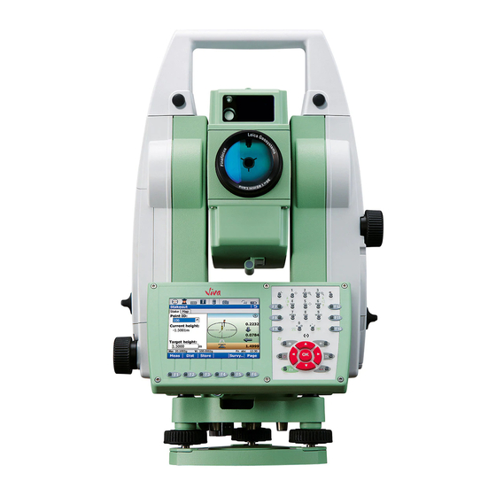
Wide-angle camera, lens PowerSearch, transmitter g) PowerSearch, receiver h) Coaxial optics for angle and distance measurement, and exit port of visible laser beam for distance measure- ments Communication side cover Horizontal drive k) Tribrach securing screw TS_081 TS11/TS15, Description of the System... - Page 26 TS11/TS15, Description of the System Instrument compo- nents part 2 of 2 a) Vertical drive b) Focusing ring c) Battery compartment d) Tribrach footscrew e) Stylus for touch screen Touch screen g) Circular level h) Interchangeable eyepiece Keyboard e f g...
- Page 27 Communication side cover a) Compartment lid b) USB stick cap storage c) USB device port (mini AB OTG) d) USB host port for USB stick e) SD card port TS_089 TS11/TS15, Description of the System...
- Page 28 TS11/TS15, Description of the System Instrument compo- nents for Smart- Station TS_084 a) SmartAntenna b) RTK slot-in device c) SmartAntenna Adapter d) Communication side cover...
- Page 29 Instrument compo- nents for RCS a) RadioHandle b) Communication side cover TS_085 TS11/TS15, Description of the System...
- Page 30 TS11/TS15, Description of the System Laser guide compo- b c d b d e nents a) Operation indicator LED, orange b) Labelling c) Horizontal adjustment screws d) Fixing screws e) Safety cover for vertical adjustment screws Laser aperture TS_122...
-
Page 31: User Interface
User Interface Keyboard Keyboard TS11/TS15 WXYZ TS_087 TS11/TS15, User Interface... - Page 32 TS11/TS15, User Interface a) Function keys F7 - F9 Windows CE b) ± key k) Favourites c) Brightness d) Alphanumeric keys m) Arrow keys, OK e) Backspace n) ENTER Volume o) Fn g) Function keys F10 - F12 p) ON/OFF...
- Page 33 Opens a selectable list. ON/OFF If the instrument is already off: Turns on the instru- ment when held for 2 s. If the instrument is already on: Turns to Power Options menu when held for 2 s. TS11/TS15, User Interface...
- Page 34 TS11/TS15, User Interface Function Favourites Goes to a favourites menu. Home Switches to the SmartWorx Viva Main Menu. Switches to the Windows CE Start Menu when pressing Fn at the same time. Arrow keys Move the focus on the screen.
-
Page 35: Operating Principles
To accept data entered into an editable Tap on the screen outside of the editable field and exit the edit mode field. To open a context-sensitive menu Tap on the item and hold for 2 s. TS11/TS15, User Interface... -
Page 36: Operation
Insert the Leica Viva Series DVD. Run the SetupViva&GR_USB_XX.exe to install the drivers necessary for Leica Viva devices. Depending on the version (32bit or 64bit) of the oper- ating system on your PC, you have to select between the three setup files following: •... - Page 37 Step Description The Welcome to InstallShield Wizard for Leica Viva & GR USB drivers window appears. Ensure that all Leica Viva devices are disconnected from your PC before you continue! Next>. The Ready to Install the Program window appears. Install. The drivers will be installed on your PC.
- Page 38 TS11/TS15, Operation Connect USB cable to computer for the first time step- by-step TS_090 Step Description Start the computer. Plug the GEV223 cable into TPS instrument. Turn on the TPS instrument. Plug the GEV223 cable into the USB port of the computer. The Found New Hardware Wizard starts up automatically.
- Page 39 Allow USB connections inside the Connection Settings window of Active- Sync. For PCs with Windows Vista or Windows 7 operating system: Windows Mobile Device Center starts up automatically. If does not start automatically, start Windows Mobile Device Center. TS11/TS15, Operation...
- Page 40 TS11/TS15, Operation Connect to computer via USB cable step-by-step TS_090 Step Description Start the PC. Plug the GEV223 cable into TS instrument. Turn on the TS instrument. Plug the GEV223 cable into the USB port of the computer. For PCs with Windows XP operating system: ActiveSync starts up automatically.
- Page 41 Click Explore in ActiveSync. The folders on the TS instrument are displayed under Mobile Devices. The folders of the data storage device can be found in either of the following folders: • Leica Geosystems\SmartWorx Viva • SD Card • USB memory device For PCs with Windows Vista or Windows 7 operating system: Windows Mobile Device Center starts up automatically.
-
Page 42: Power Functions
TS11/TS15, Operation Power Functions Turning on Press and hold power key ( ) for 2 s. TS11/TS15 instru- Instrument must have a power supply. ment Turning TS instru- Press and hold power key ( ) for 5 s. ment off TS instrument must be on. - Page 43 Reset Windows CE (resets Windows CE and communication settings to factory defaults) • Reset installed software (resets settings of all installed software) • Reset Windows CE and installed software (resets Windows CE and settings of all installed software) TS11/TS15, Operation...
-
Page 44: Batteries
+10°C to +20°C/+50°F to +68°F if possible. • It is normal for the battery to become warm during charging. Using the chargers recommended by Leica Geosystems, it is not possible to charge the battery if the temperature is too high. •... -
Page 45: Battery For The Ts Instrument
Pull out the battery housing. Pull the battery from the battery housing. A pictogram of the battery is displayed inside the battery housing. This pictogram is a visual aid to assist in placing the battery correctly. TS11/TS15, Operation... - Page 46 TS11/TS15, Operation Step Description Place the battery into the battery housing, ensuring that the contacts are facing outward. Click the battery into position. Place the battery housing into the battery compartment. Push the battery housing in until it fits completely into the battery compartment.
-
Page 47: Battery For Smartantenna
The batteries are inserted in the bottom part of the instrument. Push the slide fastener of one of the battery compartments in the direc- tion of the arrow with the open-lock symbol. Remove the cover from the battery compartment. TS11/TS15, Operation... - Page 48 TS11/TS15, Operation Step Description With the battery contacts facing upwards, slide the battery into the cover of the battery compartment. Push the battery upwards so that it locks into position. Insert the cover of the battery compartment into the compartment and push the slide fastener in the direction of the arrow with the close-lock symbol.
- Page 49 Pull out the battery housing. The battery is attached to the housing. Hold the battery housing and pull the battery from the battery housing. A polarity of the battery is displayed inside the battery housing. This is a visual aid to assist in placing the battery correctly. TS11/TS15, Operation...
- Page 50 TS11/TS15, Operation Step Description Place the battery onto the battery housing, ensuring that the contacts are facing outward. Click the battery into position. Close the battery compartment by pushing the slide fastener in the direc- tion of the arrow with the close-lock symbol.
-
Page 51: Operating The Laser Guide
The Laser Guide is automatically turned off temporarily during distance measure- ment. For instruments equipped with reflectorless EDM the Laser Guide is automatically turned off when the reflectorless laser pointer is turned on. Refer to the GeoCOM Reference Manual for further information on GeoCOM. TS11/TS15, Operation... -
Page 52: Working With The Memory Device
TS11/TS15, Operation Working with the Memory Device • Keep the card dry. • Use it only within the specified temperature range. • Do not bend the card. • Protect the card from direct impacts. Failure to follow these instructions could result in data loss and/or permanent... - Page 53 Close the lid and turn the knob to the horizontal position to lock the communication compartment. To remove the SD card, open the lid of the communication compartment and gently press on the top of the card to release it from the slot. TS11/TS15, Operation...
- Page 54 Open the lid of the communication compartment to access the communication ports. Slide the USB stick with the Leica logo facing you firmly into the USB host port until it clicks into TS_092 position.
- Page 55 Push the slide fastener of battery compartment 1 in the direction of the arrow with the open-lock symbol. Remove the cover from battery compartment 1. Slide the card firmly into the slot until it clicks into position. TS11/TS15, Operation...
- Page 56 TS11/TS15, Operation Step Description Do not force the card into the slot. The card should be held with the contacts upwards and facing the slot. To remove the card, push the slide fastener of battery compartment 1 in the direction of the arrow with the open-lock symbol and remove the cover.
-
Page 57: Working With The Rtk Device (Smartstation)
SLG2 CDMA Telit CC864-DUAL (US) SLC1, SLC2 Radios fitting into the GS15 GNSS instrument Radio Device Pacific Crest PDL, transceive SLR3-1 Pacific Crest PDL, transceive SLR3-2 Satelline 3AS, transmit SLR1 Satelline 3AS, receive SLR2 Satelline M3-TR1, transceive SLR5 TS11/TS15, Operation... - Page 58 TS11/TS15, Operation Insert and remove a slot-in-device step-by-step GS_089 Step Description Turn over the GS15 to gain access to the slot-in-device compartment. Loosen the screws of the compartment cover with the supplied Allen key. Remove the compartment cover. Attach the slot-in-device to the compartment cover.
- Page 59 This increases the height of the radio antenna and therefore maximises radio coverage. Refer to the Leica Viva GNSS Getting Started Guide for detailed information about the setup.
- Page 60 TS11/TS15, Operation Insert and remove a SIM card step-by- step GS_098 Step Description The SIM card is inserted into a slot on the side of the SLG1/SLG2. Take the SIM card and a pen. Using the pen, press the small button of the SIM card slot to eject the SIM card holder.
- Page 61 Each slot-in-device for a radio or digital cellular phones has Light Emitting Diode indi- cators on the bottom side. They indicate the basic device status. Diagram a b c d a) Mode LED, available for Satelline 3AS b) Data transfer LED c) Signal strength LED d) Power LED GS_097 TS11/TS15, Operation...
- Page 62 TS11/TS15, Operation Description of the LEDs IF the THEN Mode LED SLR1, SLR2 with the device is in the program- Satelline 3AS, ming mode controlled from the SLR5 with Satel- PC via cable. line M3-TR1 Data any device data is not being transferred.
- Page 63 GPRS PDP context activated. long break red: long flash, Packet switched data transfer is short break in progress. device is off. TS11/TS15, Operation...
- Page 64 TS11/TS15, Operation IF the THEN SLR3-1, SLR3-2 the communication link, Data with Pacific Crest Carrier Detection, is okay on the roving instrument. flashing red the communication link, Data Carrier Detection, is okay on the roving instrument, but signal is weak.
-
Page 65: Led Indicators
LED Indicators LED indicators on Description SmartAntenna The SmartAntenna has Light Emitting Diode indicators. They indicate the basic instru- ment status. Diagram (GS12) TRK Tracking LED a b c BT Bluetooth LED PWR Power LED GS_120 TS11/TS15, Operation... - Page 66 TS11/TS15, Operation Description of the LEDs (GS12) IF the THEN BT LED green Bluetooth is in data mode and ready for connecting. purple Bluetooth is connecting. blue Bluetooth has connected. flashing blue data is being transferred. PWR LED power is off.
- Page 67 Position LED d) Power LEDs e) RTK Base LED RTK Rover LED GS_091 GS_09 GS_091 Description of the LEDs (GS15) IF the THEN Bluetooth green Bluetooth is in data mode and ready for connecting. purple Bluetooth is connecting. TS11/TS15, Operation...
- Page 68 TS11/TS15, Operation IF the THEN blue Bluetooth has connected. Storage LED no SD card is inserted or GS15 is switched off. green SD card is inserted but no raw data is being logged. flashing green raw data is being logged.
- Page 69 GS15 is (passive switched off. battery flashing green power is 40% - 100%. LED is green for 1 s every 10 s. flashing yellow power is 20% - 40%. LED is yellow for 1 s every 10 s. TS11/TS15, Operation...
- Page 70 TS11/TS15, Operation IF the THEN flashing red power is less than 20%. LED is red for 1 s every 10 s. RTK Rover GS15 is in RTK base mode or GS15 is switched off. green GS15 is in rover mode. No RTK data is being received at the interface of the communication device.
- Page 71 Description RadioHandle The RadioHandle has Light Emitting Diode indicators. They indicate the basic RadioHandle status. Diagram of the LED Indicators a b c d a) Power LED b) Link LED c) Data Transfer LED d) Mode LED TS_088 TS11/TS15, Operation...
- Page 72 TS11/TS15, Operation Description of the LED Indicators IF the THEN Power LED power is off. green power is on. Link LED no radio link to field controller. radio link to field controller. Data Transfer LED no data transfer to/from field controller.
-
Page 73: Guidelines For Correct Results
EDM and the target surface as the measurement is triggered, the measurement may be made to the side of the vehicle. The result is the distance to the vehicle, not to the surface of the building. TS11/TS15, Operation... - Page 74 TS11/TS15, Operation If using the long range measurement mode (> 1000 m, > 3300 ft) to prisms, and an object passes within 30 m of the EDM as the measurement is triggered, the distance measurement may be similarly effected due to the strength of the laser signal.
- Page 75 If the prism location is changed too quickly, the target may be lost. Make sure that the speed does not exceed the figure given in the technical data. TS11/TS15, Operation...
-
Page 76: Check & Adjust
Check & Adjust Overview Description Leica Geosystems instruments are manufactured, assembled and adjusted to the best possible quality. Quick temperature changes, shock or stress can cause devia- tions and decrease the instrument accuracy. It is therefore recommended to check and adjust the instrument from time to time. This check and adjust can be done in the field by running through specific measurement procedures. - Page 77 Refer to "4.2 Preparation" to find more important points. During the manufacturing process, the instrument errors are carefully determined and set to zero. As mentioned above, these errors can change and it is highly recom- mended to redetermine them in the following situations: TS11/TS15, Check & Adjust...
- Page 78 TS11/TS15, Check & Adjust • Before the first use • Before every high precision survey • After rough or long transportation • After long working periods • After long storage periods • If the temperature difference between current environment and the temperature at the last calibration is more than 20°C...
-
Page 79: Preparation
Even after adjustment of the ATR, the crosshairs may not be positioned exactly on the centre of the prism after an ATR measurement has been completed. This outcome is a normal effect. The telescope is not normally positioned exactly on the TS11/TS15, Check & Adjust... - Page 80 TS11/TS15, Check & Adjust centre of the prism, to speed up the ATR measurement. These small deviations/ATR offsets, are calculated individually for each measurement and corrected electroni- cally. This means that the horizontal and vertical angles are corrected twice: first by the determined ATR errors for Hz and V, and then by the individual small deviations of the current aiming.
-
Page 81: Combined Adjustment (L, T, I, C And Atr)
Step Description step-by-step Main Menu: User\Check & Adjust Check & Adjust Wizard Select the option: Check & adjust the compensator, index error, line of sight error & automatic target pointing Next Face I measurement TS11/TS15, Check & Adjust... - Page 82 If Calibrate the automatic target aiming is checked and an ATR is available, the adjustment will include the determination of the ATR Hz and V adjust- ment errors. Use a clean Leica standard prism as the target. Do not use a 360° prism. Aim the telescope accurately at a target at about 100 m distant.
- Page 83 If one or more errors are bigger than the predefined limits, the procedure must be repeated. All measurements of the current run are rejected and none of them is averaged with the results from previous runs. TS11/TS15, Check & Adjust...
- Page 84 TS11/TS15, Check & Adjust Step Description Adjustment Status No. of measurements: Shows the number of runs completed. One run consists of a measurement in face I and face II. Sigma l Comp: and similar lines show the standard deviations of the deter- mined adjustment errors.
- Page 85 If the Use status is set to Yes, Next overwrites the old adjust- to be stored ment errors with the new ones. Redo rejects all new determined adjustment errors and to be determined again repeats the whole procedure. Refer to paragraph "Combined adjustment procedure step-by-step". TS11/TS15, Check & Adjust...
-
Page 86: Tilting Axis Adjustment (A)
TS11/TS15, Check & Adjust Tilting Axis Adjustment (a) Description This adjustment procedure determines the following instrument error: Tilting axis error Determination of The following table explains the most common settings. tilting axis error Step Description step-by-step Determine the horizontal collimation error (c) before starting this proce- dure. - Page 87 100 m distance or less if not possible. The target must be positioned at least 27°/30 gon above or beneath the horizontal plane. The procedure can be started in + 27° any telescope face. - 27° TS_070 TS11/TS15, Check & Adjust...
- Page 88 TS11/TS15, Check & Adjust Step Description Meas to measure and to continue to the next screen. Motorised instruments change auto- matically to the other face. 180° Non-motorised instruments guide to the other face. The fine pointing must be performed manually in both faces.
- Page 89 No more runs can be added later. Next to view the adjustment results. Select Finish to accept the results. No more runs can be added later. Select Redo to decline all measurements and to repeat all calibration runs. TS11/TS15, Check & Adjust...
- Page 90 TS11/TS15, Check & Adjust Next step IF the results are THEN Next overwrites the old tilting axis error with the new one. to be stored Redo rejects the new determined tilting axis error and repeats to be determined again the whole procedure. Refer to paragraph "Determination of...
-
Page 91: Adjusting The Circular Level Of The Instrument And Tribrach
Using the tribrach footscrews, level the instrument with the electronic level. Select Instrument\TPS settings\Level bubble & compensator to access the Level Bubble & Compensator screen. Check the position of the circular level on the instrument and tribrach. TS11/TS15, Check & Adjust... - Page 92 TS11/TS15, Check & Adjust Step Description a) If both circular levels are centred, no adjustments are necessary b) If one or both circular levels are not centred, adjust as follows: Instrument: If it extends beyond the circle, use the supplied allen key to centre it with the adjustment screws.
-
Page 93: Adjusting The Circular Level Of The Prism Pole
If the circular level is not centred, use an allen key to centre it with the adjustment screws. After the adjustments, all adjusting screws must have the same tightening tension and no adjusting screw should be loose. TS11/TS15, Check & Adjust... -
Page 94: Inspecting The Laser Plummet Of The Instrument
The laser plummet is located in the vertical axis of the instrument. Under normal conditions of use, the laser plummet does not need adjusting. If an adjustment is necessary due to external influences, return the instrument to any Leica Geosystems authorised service workshop. - Page 95 If the centre of the laser dot describes a perceptible circular movement, or moves more than 3 mm away from the point which was first marked, an adjustment may be required. Inform your nearest Leica Geosystems authorised service workshop. Depending on brightness and surface, the diameter of the laser dot can vary.
-
Page 96: Adjusting The Laser Guide
TS11/TS15, Check & Adjust Adjusting the Laser Guide To avoid moisture or dust entering the Laser Guide compartment, adjustment screws and screw covers must be fixed after each adjustment procedure. Adjustment The recommended adjustment procedure is designed for distances of 50 m and 120 m. - Page 97 TS_123 TS11/TS15, Check & Adjust...
- Page 98 TS11/TS15, Check & Adjust Laser guide screws a) Horizontal adjustment screw b) Fixing screw c) Fixing screw d) Horizontal adjustment screw e) Vertical adjustment screw Vertical adjustment screw TS_124 g) Safety cover screw h) Safety cover Laser Guide adjust- This step-by-step description describes the Laser Guide adjustment for a distance of ment step-by-step 50 m.
- Page 99 Finish the horizontal adjustment by tightening the fixing screws (b) and (c). Vertical adjustment: Loosen the vertical adjustment screw (e) as much as to move the laser beam slightly upon of the upper crosshairs on the target plate. TS11/TS15, Check & Adjust...
- Page 100 TS11/TS15, Check & Adjust Step Description Fix the vertical adjustment by tightening the vertical adjustment screw (f). Fixing this screw moves the laser beam exactly to the crosshairs centre. Finish the vertical adjustment by moving the safety cover (h) to its original position and by tightening the safety cover screw (g).
-
Page 101: Servicing The Tripod
Tighten the leg cap screws moderately, with the supplied allen key. Tighten the articulated joints on the tripod head enough to keep the tripod legs open when lifting the tripod off the ground. Tighten the allen screws of the tripod legs. TS11/TS15, Check & Adjust... -
Page 102: Care And Transport
Always carry the product in its transport container and secure it. Shipping When transporting the product by rail, air or sea, always use the complete original Leica Geosystems packaging, transport container and cardboard box, or its equiva- lent, to protect against shock and vibration. Shipping, transport... - Page 103 Field adjustment After transport inspect the field adjustment parameters given in this user manual before using the product. TS11/TS15, Care and Transport...
-
Page 104: Storage
TS11/TS15, Care and Transport Storage Product Respect the temperature limits when storing the equipment, particularly in summer if the equipment is inside a vehicle. Refer to "7 Technical Data" for information about temperature limits. Field adjustment After long periods of storage inspect the field adjustment parameters given in this user manual before using the product. -
Page 105: Cleaning And Drying
Dry the product, the transport container, the foam inserts and the accessories at a temperature not greater than 40°C /104°F and clean them. Do not repack until every- thing is completely dry. Always close the transport container when using in the field. TS11/TS15, Care and Transport... - Page 106 TS11/TS15, Care and Transport Cables and plugs Keep plugs clean and dry. Blow away any dirt lodged in the plugs of the connecting cables.
-
Page 107: Maintenance
Maintenance Motorisation An inspection of the motorisation in motorised instruments must be done in a Leica Geosystems authorised service workshop. Following conditions: • After about 4000 hours operation. • Twice a year in case of permanent use of the instrument, for example in moni- toring applications. -
Page 108: Safety Directions
TS11/TS15, Safety Directions Safety Directions General Introduction Description The following directions enable the person responsible for the product, and the person who actually uses the equipment, to anticipate and avoid operational hazards. The person responsible for the product must ensure that all users understand these... -
Page 109: Intended Use
• Measuring raw data and computing coordinates using carrier phase and code signal from GNSS satellites. • Carrying out measurement tasks using various GNSS measuring techniques. • Recording GNSS and point related data. • Computing with software. TS11/TS15, Safety Directions... - Page 110 TS11/TS15, Safety Directions Adverse use • Use of the product without instruction. • Use outside of the intended limits. • Disabling safety systems. • Removal of hazard notices. • Opening the product using tools, for example screwdriver, unless this is permitted for certain functions.
-
Page 111: Limits Of Use
Danger Local safety authorities and safety experts must be contacted before working in hazardous areas, or close to electrical installations or similar situations by the person in charge of the product. TS11/TS15, Safety Directions... -
Page 112: Responsibilities
Manufacturers of The manufacturers of non Leica Geosystems accessories for the product are respon- non Leica Geosys- sible for developing, implementing and communicating safety concepts for their... - Page 113 The person responsible for the product must ensure that it is used in accordance with the instructions. This person is also accountable for the training and the deployment of personnel who use the product and for the safety of the equipment in use. TS11/TS15, Safety Directions...
-
Page 114: Hazards Of Use
TS11/TS15, Safety Directions Hazards of Use Warning The absence of instruction, or the inadequate imparting of instruction, can lead to incorrect or adverse use, and can cause accidents with far-reaching human, material, financial and environmental consequences. Precautions: All users must follow the safety directions given by the manufacturer and the direc- tions of the person responsible for the product. - Page 115 Do not use the product in a thunderstorm. Caution Be careful when pointing the product towards the sun, because the telescope func- tions as a magnifying glass and can injure your eyes and/or cause damage inside the product. TS11/TS15, Safety Directions...
- Page 116 Always ensure that the working site is adequately secured. Adhere to the regulations governing safety and accident prevention and road traffic. Warning Only Leica Geosystems authorised service workshops are entitled to repair these products. Warning If computers intended for use indoors are used in the field there is a danger of elec-...
- Page 117 Before transportation or shipping contact your local passenger or freight transport company. Warning Using a battery charger not recommended by Leica Geosystems can destroy the batteries. This can cause fire or explosions. TS11/TS15, Safety Directions...
- Page 118 TS11/TS15, Safety Directions Precautions: Only use chargers recommended by Leica Geosystems to charge the batteries. Warning High mechanical stress, high ambient temperatures or immersion into fluids can cause leakage, fire or explosions of the batteries. Precautions: Protect the batteries from mechanical influences and high ambient temperatures. Do not drop or immerse batteries into fluids.
- Page 119 Always prevent access to the product by unauthorised personnel. Product-specific treatment and waste management information can be downloaded from the Leica Geosystems home page at http://www.leica- geosystems.com/treatment or received from your Leica Geosystems dealer. TS11/TS15, Safety Directions...
-
Page 120: Laser Classification
TS11/TS15, Safety Directions Laser Classification 6.6.1 General General The following directions (in accordance with the state of the art - international standard IEC 60825-1 (2007-03) and IEC TR 60825-14 (2004-02)) provide instruc- tion and training information to the person responsible for the product and the person who actually uses the equipment, to anticipate and avoid operational hazards. -
Page 121: Distancer, Measurements With Reflectors (Ir Mode)
Description Value Maximum average radiant power 0.33 mW Pulse duration 800 ps Pulse repetition frequency 100 MHz - 150 MHz Wavelength 650 nm - 690 nm TS11/TS15, Safety Directions... - Page 122 TS11/TS15, Safety Directions Labelling Art.No.: Type: TS..Class 1 Laser Product ..Equip.No.: ..S.No.: according to IEC 60825-1 Power: 12V/7,4V ---, 1A max ..Leica Geosystems AG...
-
Page 123: Distancer, Measurements Without Reflectors (Rl Mode)
(e.g.) beam alignment with the pupil, worst case accommodation, b) inherent safety margin in the maximum permissible exposure to laser radiation (MPE), c) natural aversion behaviour for exposure to bright light for the case of visible radi- ation. TS11/TS15, Safety Directions... - Page 124 TS11/TS15, Safety Directions Description Value (R400/R1000) Maximum average radiant power 5.00 mW Pulse duration 800 ps Pulse repetition frequency 100 MHz - 150 MHz Wavelength 650 nm - 690 nm Beam divergence 0.2 mrad x 0.3 mrad NOHD (Nominal Ocular Hazard Distance) @ 0.25s...
- Page 125 Do not look through or beside the optical sight at prisms or reflecting objects when the laser is switched on, in laser pointer or distance measurement mode. Aiming at prisms is only permitted when looking through the telescope. TS11/TS15, Safety Directions...
- Page 126 TS11/TS15, Safety Directions Labelling Laser Aperture Laser Radiation Avoid direct eye exposure Class 3R Laser Product according to IEC 60825-1 (2007 - 03) Po ≤ 5.00 mW λ = 650-690 nm TS_097 a) Laser beam...
- Page 127 This device complies with part 15 of the FCC Rules. Operation is subject to the following two conditions: (1) This device may not cause harmful interference, and (2) this device must accept any interference received, including interference that may cause undesired operation. TS_129 TS11/TS15, Safety Directions...
-
Page 128: Automatic Target Aiming Atr
TS11/TS15, Safety Directions 6.6.4 Automatic Target Aiming ATR General The Automatic Target Aiming built into this product produces an invisible laser beam which emerges from the telescope objective. The laser product described in this section is classified as laser class 1 in accordance with: •... - Page 129 This device complies with part 15 of the FCC Rules. Operation is subject to the following two conditions: (1) This device may not cause harmful interference, and (2) this device must accept any interference received, including interference that may cause undesired operation. TS_096 a) Laser beam TS11/TS15, Safety Directions...
-
Page 130: Powersearch Ps
TS11/TS15, Safety Directions 6.6.5 PowerSearch PS General The PowerSearch built into this product produces an invisible laser beam which emerges from the telescope objective. The laser product described in this section is classified as laser class 1 in accordance with: •... - Page 131 This device complies with part 15 of the FCC Rules. Operation is subject to the following two conditions: (1) This device may not cause harmful interference, and (2) this device must accept any interference received, including interference that may cause undesired operation. TS_098 Laser beam TS11/TS15, Safety Directions...
-
Page 132: Electronic Guide Light Egl
TS11/TS15, Safety Directions 6.6.6 Electronic Guide Light EGL General The integrated Electronic Guide Light produces a visible LED beam from the front side of the telescope. The product described in this section, is excluded from the scope of IEC 60825-1 (2007-03): "Safety of laser products". -
Page 133: Laser Plummet
Description Value Maximum average radiant power 0.95 mW Pulse duration c.w. Pulse repetition frequency c.w. Wavelength 635 nm Warning From a safety perspective class 2 laser products are not inherently safe for the eyes. TS11/TS15, Safety Directions... - Page 134 TS11/TS15, Safety Directions Precautions: Avoid staring into the beam or pointing the beam at other people. Labelling Art.No.: Type: TS..Equip.No.: ..S.No.: Power: 12V/7,4V ---, 1A max ..
- Page 135 TS_100 a) Laser beam b) Exit for laser beam TS11/TS15, Safety Directions...
-
Page 136: Laser Guide
TS11/TS15, Safety Directions 6.6.8 Laser Guide General The Laser Guide built into the TS15 G instrument produces a visible, red laser beam, which emerges from the front section of the telescope. The laser product described in this section, is classified as laser class 3R in accord- ance with: •... - Page 137 Do not aim at areas that are essentially reflective, such as a mirror, or which could emit unwanted reflections. Do not look through or beside the optical sight at prisms or reflecting objects when the laser is switched on, in laser pointer or distance meas- TS11/TS15, Safety Directions...
- Page 138 TS11/TS15, Safety Directions urement mode. Aiming at prisms is only permitted when looking through the tele- scope. Warning In remote controlled systems the laser beam can be moved automatically via serial interface commands without direct control of the user. Precautions: Check carefully if the laser beam is automatically turned off at beam movements of more than approximately 5°...
- Page 139 But, more importantly, at flat or concave mirror-like surfaces. * The hazard distance is the distance from the laser at which beam irradiance or radiant exposure equals the maximum permissible value to which personnel may be exposed without being exposed to a health risk. TS11/TS15, Safety Directions...
- Page 140 TS11/TS15, Safety Directions Products with an integrated Laser Guide of laser class 3R this hazard distance is 128 m / 420 ft. At this distance, the laser beam rates as class 1, that means direct intra- beam viewing is not hazardous.
- Page 141 Labelling Laser Aperture Laser Radiation Avoid direct eye exposure Class 3R Laser Product according to IEC 60825-1 (2001 - 08) Po ≤ 4.75 mW λ = 650-690 nm TS_125 a) Laser beam TS11/TS15, Safety Directions...
- Page 142 TS11/TS15, Safety Directions ........
-
Page 143: Electromagnetic Compatibility Emc
Warning Electromagnetic radiation can cause disturbances in other equipment. Although the product meets the strict regulations and standards which are in force in this respect, Leica Geosystems cannot completely exclude the possibility that other equipment may be disturbed. Caution There is a risk that disturbances may be caused in other equipment if the product is used with accessories from other manufacturers, for example field computers, personal computers, two-way radios, non-standard cables or external batteries. - Page 144 Although the product meets the strict regulations and standards which are in force in this respect, Leica Geosystems cannot completely exclude the possibility that the product may be disturbed by intense electromagnetic radiation, for example, near radio transmitters, two-way radios or diesel generators.
- Page 145 Precautions: Although the product meets the strict regulations and standards which are in force in this respect, Leica Geosystems cannot completely exclude the possibility that other equipment can be disturbed or that humans or animals can be affected. •...
-
Page 146: Fcc Statement, Applicable In U
TS11/TS15, Safety Directions FCC Statement, Applicable in U.S. The greyed paragraph below is only applicable for products without radio. Warning This equipment has been tested and found to comply with the limits for a Class B digital device, pursuant to part 15 of the FCC rules. - Page 147 Warning Changes or modifications not expressly approved by Leica Geosystems for compli- ance could void the user's authority to operate the equipment. Labelling ....
- Page 148 TS11/TS15, Safety Directions Labelling GS15 This device complies with part 15 of the FCC Rules. Type: ... S.No.: ..Operation is subject to the following two conditions: Equi.No.: .
- Page 149 Manufactured: ..and (2) this device must accept any Made in Switzerland interference received, Contains including interference Transmitter Module: that may cause FCC ID: HSW-2400M IC: 4492A-2450 S.No.: XXXXXX undesired operation. TS_102 TS11/TS15, Safety Directions...
-
Page 150: Technical Data
TS11/TS15, Technical Data Technical Data Angle Measurement Accuracy Available Standard devia- Display resolution angular accu- tion Hz, V, racies ISO 17123-3 ["] [mgon] ["] [°] [mgon] [mil] 0.0001 0.01 0.0001 0.01 0.0001 0.01 0.0001 0.01 Characteristics Absolute, continuous, diametric. -
Page 151: Distance Measurement With Reflectors (Ir Mode)
3300 Mini prism (GMP101) 2600 1200 4000 2000 7000 Reflector tape (GZM31) 60 mm x 60 mm Machine Automation power 2600 1500 5000 2000 7000 prism (MPR122) For Machine Control purposes only! Shortest measuring distance: 1.5 m TS11/TS15, Technical Data... - Page 152 TS11/TS15, Technical Data Atmospheric condi- Range A: Strong haze, visibility 5 km; or strong sunlight, severe heat shimmer Range B: Light haze, visibility about 20 km; or moderate sunlight, slight heat tions shimmer Range C: Overcast, no haze, visibility about 40 km; no heat shimmer Measurements can be made to reflector tapes over the entire range without external ancillary optics.
- Page 153 Principle: Phase measurement Characteristics Type: Coaxial, visible red laser Carrier wave: 658 nm Measuring system: System analyser basis 100 MHz - 150 MHz TS11/TS15, Technical Data...
-
Page 154: Distance Measurement Without Reflectors (Rl Mode)
TS11/TS15, Technical Data Distance Measurement without Reflectors (RL mode) Range Type Kodak Gray Range D Range E Range F Card [ft] [ft] [ft] R400 White side, 90 % >400 >1310 reflective R400 Grey side, 18 % >200 >660 reflective R1000... - Page 155 Coaxial, visible red laser Characteristics Carrier wave: 658 nm Measuring system: System analyser basis 100 MHz - 150 MHz Laser dot size Distance [m] Laser dot size, approximately [mm] at 30 7 x 10 at 50 8 x 20 TS11/TS15, Technical Data...
-
Page 156: Distance Measurement - Long Range (Lo Mode)
TS11/TS15, Technical Data Distance Measurement - Long Range (LO mode) Range The range of the long range measurements is the same for R400 and R1000. Reflector Range A Range B Range C [ft] [ft] [ft] Standard prism (GPR1) 2200 7300... - Page 157 The display resolution is 0.1 mm. Principle: Phase measurement Characteristics Type: Coaxial, visible red laser Carrier wave: 658 nm Measuring system: System analyser basis 100 MHz - 150 MHz TS11/TS15, Technical Data...
-
Page 158: Automatic Target Aiming Atr
TS11/TS15, Technical Data Automatic Target Aiming ATR Range ATR/LOCK Reflector Range ATR mode Range Lock mode [ft] [ft] Standard prism (GPR1) 1000 3300 2600 360° prism (GRZ4, GRZ122) 2600 2000 360° Mini prism (GRZ101) 1150 1000 Mini prism (GMP101) 1600... - Page 159 ± 1 mm. Above a certain distance, the instrument angle accuracy predominates and takes over the standard deviation of the ATR. • The following graph shows the ATR standard deviation based on three different prism types, distances and instrument accuracies. TS11/TS15, Technical Data...
- Page 160 TS11/TS15, Technical Data 5” 3” 2” GRZ4 1.5” 1” GRZ122 TS_103 Leica GRZ4 prism (360°) Leica GRZ122 prism (360°)
- Page 161 Leica circular prisms and Leica circular Mini prisms ATR accuracy [mm] Distance measurement [m] " Instrument angle accuracy ["] Maximum tangential speed: 5 m/s at 20 m; 25 m/s at 100 m Maximum speed in Maximum radial speed with Measure...
-
Page 162: Powersearch Ps
TS11/TS15, Technical Data PowerSearch PS Range Reflector Range PS [ft] Standard prism (GPR1) 1000 360° prism (GRZ4, GRZ122) 300* 1000* Mini prism (GMP101) Machine Automation power prism (MPR122) 300* 1000* For Machine Control purposes only! Measurements at the vertical limits of the fan or under unfavourable atmospheric conditions may reduce the maximum range. -
Page 163: Wide-Angle Camera
2 m (6.6 ft) to infinity at zoom level 1 x 7.5 m (24.6 ft) to infinity at zoom level 4 x Image storage: JPEG up to 5 Mpixel (2560 x 1920) Zoom: 3-step (1x, 2x, 4x) Whitebalance: User configurable Brightness: User configurable TS11/TS15, Technical Data... -
Page 164: Smartstation
TS11/TS15, Technical Data SmartStation 7.8.1 SmartStation Accuracy Measurement precision and accuracy in position and accuracy in height are dependent upon various factors including the number of satellites tracked, constel- lation geometry, observation time, ephemeris accuracy, ionospheric disturbance, multipath and resolved ambiguities. Figures quoted assume normal to favourable conditions. - Page 165 Formats for data reception: Leica proprietary GPS and GNSS real-time data formats, RTK data formats CMR, CMR+, RTCM V2.1 / 2.2 / 2.3 / 3.1 TS11/TS15, Technical Data...
-
Page 166: Smartstation Dimensions
TS11/TS15, Technical Data 7.8.2 SmartStation Dimensions SmartStation Dimensions 226 mm 226 mm TS_119... -
Page 167: Smartantenna Technical Data
SmartAntenna. Type Description GS12 GPS, GLONASS, Galileo, Compass With CS10/CS15 field SmartTrack+ antenna with built in controller or Leica Viva TPS groundplane. instruments. GS15 GPS, GLONASS, Galileo, Compass With CS10/CS15 field SmartTrack+ antenna with built in controller or Leica Viva TPS groundplane. - Page 168 TS11/TS15, Technical Data Weight Instrument weights without battery and radio: Type Weight [kg]/[lbs] GS12 0.94/2.07 GS15 1.34/2.95 Power Power consumption: GS12: 1.8 W typically GS15, radio excluded: 3.2 W typically External supply voltage: Nominal 12 V DC ( , GEV71 car battery cable to a 12 V car battery), voltage range 10.5 V-28 V DC...
- Page 169 Galileo E5a 1176.45 MHz Galileo E5b 1207.14 MHz Galileo Alt-BOC 1191.795 MHz Gain Typically 27 dBi Typically 27 dBi Noise Figure Typically < 2 dBi Typically < 2 dBi Galileo Alt-BOC covers bandwidth of Galileo E5a and E5b. TS11/TS15, Technical Data...
- Page 170 TS11/TS15, Technical Data Environmental Temperature specifications Operating temperature [°C] Storage temperature [°C] -40 to +65 -40 to +80 Bluetooth: -30 to +65 Protection against water, dust and sand Protection IP67 (IEC 60529) Dusttight Protected against water jets Waterproof to 1 m temporary immersion...
-
Page 171: Laser Guide Technical Data
Line of sight offset: 52.20 mm Optics Focussing distance: 22.76 mm Beam angle: 0.09 mrad Power supply: From instrument Power Power consumption: ca. 0.2 W Environmental Temperature specifications Operating temperature [°C] Storage temperature [°C] -20 to +50 -40 to +70 TS11/TS15, Technical Data... - Page 172 TS11/TS15, Technical Data Range Daylight: 250 m Darkness: 500 m Beam diameter The laser beam diameter is influenced by the intensity of the laser guide, by the appli- cation distance, by the characteristics of the surface and by the ambient light.
-
Page 173: Conformity To National Regulations
Conformity to • FCC Part 15 (applicable in US) • Hereby, Leica Geosystems AG, declares that the Communication side cover with national regula- Bluetooth is in compliance with the essential requirements and other relevant tions provisions of Directive 1999/5/EC. The declaration of conformity may be consulted at http://www.leica-geosystems.com/ce. -
Page 174: Radiohandle
FCC Part 15 (applicable in US) national regula- • Hereby, Leica Geosystems AG, declares that the RadioHandle is in compliance with the essential requirements and other relevant provisions of Directive tions 1999/5/EC. The declaration of conformity may be consulted at http://www.leica- geosystems.com/ce. - Page 175 Type: Patch antenna (omnidirectional) Antenna Gain: 2 dBi Connector: TS11/TS15, Technical Data...
-
Page 176: Gs12
FCC Part 15, 22 and 24 (applicable in US) national regula- • Hereby, Leica Geosystems AG, declares that the product GS12 is in compliance with the essential requirements and other relevant provisions of Directive tions 1999/5/EC. The declaration of conformity can be consulted at http://www.leica- geosystems.com/ce. - Page 177 Type Frequency band [MHz] Bluetooth 2402 - 2480 Output power Type Output power [mW] GNSS Receive only Bluetooth GNSS Internal GNSS antenna element (receive only) Antenna Bluetooth Type: Internal Microstrip antenna Gain: 1.5 dBi TS11/TS15, Technical Data...
-
Page 178: Gs15
FCC Part 15, 22 and 24 (applicable in US) national regula- • Hereby, Leica Geosystems AG, declares that the product GS15 is in compliance with the essential requirements and other relevant provisions of Directive tions 1999/5/EC. The declaration of conformity can be consulted at http://www.leica- geosystems.com/ce. - Page 179 Frequency band [MHz] Bluetooth 2402 - 2480 Output power Type Output power [mW] GNSS Receive only Bluetooth Antenna Type Antenna Gain Connector Frequency [dBi] band [MHz] GNSS Internal GNSS antenna element (receive only) Bluetooth Internal Microstrip antenna TS11/TS15, Technical Data...
-
Page 180: Slr1, Slr2, Satel Satelline-3As
FCC Part 15 (applicable in US) national regula- • Hereby, Leica Geosystems AG, declares that the product SLR1, SLR2 is in compli- ance with the essential requirements and other relevant provisions of Directive tions 1999/5/EC. The declaration of conformity can be consulted at http://www.leica- geosystems.com/ce. - Page 181 The product must be used with the recommended antenna. A separation distance of at least 20 centimetres should be kept between the antenna and the body of the user or nearby person within the intended application. TS11/TS15, Technical Data...
-
Page 182: Slr5, Satel Satelline M3-Tr1
FCC Part 15 (applicable in US) national regula- • Hereby, Leica Geosystems AG, declares that the product SLR5 is in compliance with the essential requirements and other relevant provisions of Directive tions 1999/5/EC. The declaration of conformity can be consulted at http://www.leica- geosystems.com/ce. - Page 183 The product must be used with the recommended antenna. A separation distance of at least 20 centimetres should be kept between the antenna and the body of the user or nearby person within the intended application. TS11/TS15, Technical Data...
-
Page 184: Slr3-1, Slr3-2, Pacific Crest Adl
FCC Part 15 (applicable in US) national regula- • Hereby, Leica Geosystems AG, declares that the product SLR3-1, SLR3-2 is in compliance with the essential requirements and other relevant provisions of tions Directive 1999/5/EC. The declaration of conformity can be consulted at http://www.leica-geosystems.com/ce. - Page 185 The product must be used with the recommended antenna. A separation distance of at least 20 centimetres should be kept between the antenna and the body of the user or nearby person within the intended application. TS11/TS15, Technical Data...
- Page 186 FCC Part 15, 22 and 24 (applicable in US) national regula- • Hereby, Leica Geosystems AG, declares that the SLG1 is in compliance with the essential requirements and other relevant provisions of Directive 1999/5/EC. The tions declaration of conformity may be consulted at http://www.leica-geosys- tems.com/ce.
- Page 187 The product must be used with the recommended antenna. A separation distance of at least 20 centimetres should be kept between the antenna and the body of the user or nearby person within the intended application. TS11/TS15, Technical Data...
- Page 188 FCC Part 15, 22 and 24 (applicable in US) national regula- • Hereby, Leica Geosystems AG, declares that the SLG2 is in compliance with the essential requirements and other relevant provisions of Directive 1999/5/EC. The tions declaration of conformity may be consulted at http://www.leica-geosys- tems.com/ce.
- Page 189 The product must be used with the recommended antenna. A separation distance of at least 20 centimetres should be kept between the antenna and the body of the user or nearby person within the intended application. TS11/TS15, Technical Data...
- Page 190 TS11/TS15, Technical Data 7.10.10 SLC1 (US), SLC2 (US) CDMA Telit CC864-DUAL Conformity to • FCC Part 15, 22 and 24 (applicable in US) national regula- • The conformity for countries with other national regulations not covered by the tions FCC part 15, 22 and 24 has to be approved prior to use and operation.
- Page 191 The product must be used with the recommended antenna. A separation distance of at least 20 centimetres should be kept between the antenna and the body of the user or nearby person within the intended application. TS11/TS15, Technical Data...
-
Page 192: General Technical Data Of The Instrument
TS11/TS15, Technical Data 7.11 General Technical Data of the Instrument Magnification: 30 x Telescope Free Objective aperture: 40 mm Focusing: 1.7 m/5.6 ft to infinity Field of view: 1°30’/1.66 gon. 2.7 m at 100 m Compensator Angular accuracy Setting accuracy Setting range TS11/TS15 ["]... - Page 193 • Hotshoe connection for RadioHandle and SmartAntenna Adapter with SmartStation. • This port is located on top of Communication side cover. Port 3 • Bluetooth module for communication. • This port is housed within Communication side cover. TS11/TS15, Technical Data...
- Page 194 TS11/TS15, Technical Data Port Name Description USB host • USB memory stick port for data transfer. port USB device • Cable connections from USB devices for communication port and data transfer. Instrument Dimen- sions 101.5 mm 101.5 mm 203 mm...
- Page 195 Accuracy: Deviation from plumbline: 1.5 mm (2 sigma) at 1.5 m instrument height Diameter of laser point: 2.5 mm at 1.5 m instrument height Type: Endless horizontal and vertical drives Drives Motorisation Maximum rotating speed: 50 gon/s TS11/TS15, Technical Data...
- Page 196 TS11/TS15, Technical Data Power External supply voltage: Nominal voltage 12.8 V DC, Range 11.5 V-13.5 V Type: Li-Ion Internal battery Voltage: 7.4 V Capacity: GEB221: 4.4 Ah Type: NiMH External battery Voltage: 12 V Capacity: GEB171: 9.0 Ah...
- Page 197 Protection against water, dust and sand Type Protection All instruments IP55 (IEC 60529) Humidity Type Protection All instruments Max 95 % non condensing The effects of condensation are to be effectively counter- acted by periodically drying out the instrument. TS11/TS15, Technical Data...
- Page 198 TS11/TS15, Technical Data Arctic model - TS11 Operating range: -35°C to +50°C (-31°F to +122°F) To minimise unavoidable slowdown of display perform- ance for the Arctic option connect the external battery. Allow for a short warm-up time. Reflectors Type Additive Constant [mm] ATR...
- Page 199 The following automatic corrections are made: tions • Line of sight error • Vertical index error • Tilting axis error • Standing axis tilt • Earth curvature • Refraction • Circle eccentricity • ATR zero point error • Compensator index error TS11/TS15, Technical Data...
-
Page 200: Scale Correction
TS11/TS15, Technical Data 7.12 Scale Correction Use of scale correc- By entering a scale correction, reductions proportional to distance can be taken into tion account. • Atmospheric correction. • Reduction to mean sea level. • Projection distortion. Atmospheric The slope distance displayed is correct if the scale correction in ppm, mm/km, which correction ΔD1... - Page 201 [nm] combined EDM 1.0002863 The index n is calculated from the formula of Barrel and Sears, and is valid for: Air pressure p: 1013.25 mbar Air temperature t: 12 °C Relative air humidity h: 60 % TS11/TS15, Technical Data...
- Page 202 TS11/TS15, Technical Data Formulas Formula for visible red laser 0.29525 · p 4.126 · 10 · h ΔD = 286.34 - · 10 TS_105 ΔD Atmospheric correction [ppm] Air pressure [mbar] Air temperature [°C] Relative humidity [%] α 273.15 (7.5 * t/(237.3 + t)) + 0.7857 If the basic value of 60 % relative humidity as used by the EDM is retained, the maximum possible error in the calculated atmospheric correction is 2 ppm, 2 mm/km.
- Page 203 Projection distortion [ppm] ΔD · 10 Easting, distance from projection zero line with the scale factor 1 [km] TS_107 6.378 * 106 m In countries where the scale factor is not unity, this formula cannot be directly applied. TS11/TS15, Technical Data...
- Page 204 TS11/TS15, Technical Data Atmospheric Atmospheric corrections in ppm with temperature [°C], air pressure [mb] and height corrections °C [m] at 60 % relative humidity. 550 mb 1000 1050 mb 50°C 50°C 40°C 40°C 30°C 30°C 20°C 20°C 10°C 10°C 0°C 0°C...
- Page 205 50°F 50°F 40°F 40°F 30°F 30°F 20°F 20°F 10°F 10°F 0°F 0°F -10°F -10°F -20°F -20°F 18 19 20 21 22 23 24 25 26 27 28 29 30 31 32 inch Hg [ ft ] TS_109 TS11/TS15, Technical Data...
-
Page 206: Reduction Formulas
TS11/TS15, Technical Data 7.13 Reduction Formulas Measurements a) Mean Sea Level b) Instrument c) Reflector Slope distance Horizontal distance Height difference TS_110 Reflector types The reduction formulas are valid for measurements to all reflector types: • measurements to prisms, to reflector tape and reflectorless measurements. - Page 207 Main Menu: Config...\Instrument Settings...\TPS Corrections) are auto- matically taken into account when calculating the horizontal distance and height difference. The calculated horizontal distance relates to the station height and not to the reflector height. TS11/TS15, Technical Data...
- Page 208 TS11/TS15, Technical Data Distance meas- In the distance measuring program Averaging, the following values are displayed: uring program Slope distance as arithmetic mean of all measurements Averaging Standard deviation of a single measurement Number of measurements These values are calculated as follows: Slope distance as arithmetic mean of ·...
- Page 209 Standard deviation of the arithmetic mean of the distance Standard deviation of a single meas- TS_116 urement Number of measurements TS11/TS15, Technical Data...
- Page 210 Leica Geosystems. Such software is protected by copy- right and other laws and its use is defined and regulated by the Leica Geosystems Software Licence Agreement, which covers aspects such as, but not limited to, Scope of the Licence, Warranty, Intellectual Property Rights, Limitation of Liability, Exclusion of other Assurances, Governing Law and Place of Jurisdiction.
- Page 211 You must not install or use the software unless you have read and accepted the terms and conditions of the Leica Geosystems Software Licence Agreement. Installa- tion or use of the software or any part thereof, is deemed to be an acceptance of all the terms and conditions of such Licence Agreement.
- Page 212 TS11/TS15, Index Index Adjustment Errors View current ...........77 Accuracy Angle measurement ..........150 Angle measurement ........150 Antenna IR mode ............152 Communication side cover ......173 LO mode ............157 GS15 ............179 RL mode ............155 RadioHandle ..........175 SmartStation ..........164 Antennas ActiveSync ............
- Page 213 Drives ..............195 Technical data ..........173 Compensator ............ 192 Control unit ............193 Electrical data, SmartAntenna ......169 Corrections Electronic Adjustment ..........76 Automatic ............ 199 Electronic Distance Measurement EDM Scale ............200 Description .............14 PinPoint R400, PinPoint R1000 .......15 TS11/TS15, Index...
- Page 214 TS11/TS15, Index Electronic Guide Light EGL Frequency Band Description ............ 15 Communication side cover ......173 Safety directions .......... 132 RadioHandle ..........174 Technical data ..........199 Environmental specifications GAT 1, antenna .........181, 183, 185 Laser guide ..........171 GAT 2, antenna .........181, 183, 185 Environmental Specifications ......
- Page 215 Description of ..........33 Integrated Distancer, Visible Laser ....123 ENTER key ............33 PowerSearch PS ...........130 ESC key ............33 Laser guide Favourites ............34 Safety directiony ..........136 Fn key ............33 Laser guide components ........30 Function keys ..........33 TS11/TS15, Index...
- Page 216 TS11/TS15, Index Laser plummet Operating Temperature Inspect ............94 Laser guide ..........171 Safety directions .......... 133 SmartAntenna ..........170 Technical data ..........195 Output power GS10 ............179 Slot-in-device ..........61 GS12 ............177 Slot-in-device, description ......62 GS15 ............179 LEICA SLC1, Telit CC864-DUAL ........190 Geo Office .............
- Page 217 Insert ..........53, 54, 55 Technical data ..........174 Memory device ..........23 Recording ............195 Remove ..........53, 54, 55 Reduction Formulas .......... 206 SIM card Reflectors ............198 Insert .............60 Remove Remove ............60 SD card ............ 53, 54 SLC1 ..............190 TS11/TS15, Index...
- Page 218 TS11/TS15, Index SLC2 ..............190 Software SLG1 ..............186 Applications ...........19 SLG2 ..............188 Customised applications .........20 Slot-in-device Software type ..........19 Insert ............. 58 Upload ............21 Remove ............58 Software Licence Agreement ......210 SLR1 ..............180 Specifications, environmental SLR2 ..............180 SmartAntenna ..........170...
- Page 219 Restart ............43 Available models ..........17 Windows Mobile Device Center ......36 Firmware for TS11 and TS15 ......19 Language software for TS11 and TS15 ... 19 Lock keyboard ..........42 Power Options menu ........42 Unlock keyboard ..........42 TS11/TS15, Index...
- Page 220 International Standards of Quality Management and Quality Systems (ISO standard 9001) and Environmental Management Systems (ISO standard 14001). Ask your local Leica Geosystems dealer for more information about our TQM program. Leica Geosystems AG Heinrich-Wild-Strasse...
Need help?
Do you have a question about the TS11 and is the answer not in the manual?
Questions and answers