Table of Contents
Advertisement
Quick Links
Advertisement
Table of Contents

Related Manuals for Leica HDS7000


Summary of Contents for Leica HDS7000
- Page 1 HDS7000 User Manual Version 1.1 English...
- Page 2 The type and the serial number of your product are indicated on the type plate. identification Enter the model and serial number in your manual and always refer to this informa- tion when you need to contact your agency or Leica Geosystems authorised service workshop. Type: _______________ Serial No.:...
- Page 3 Important paragraphs which must be adhered to in practice as they enable the product to be used in a technically correct and efficient manner. Trademarks • Windows is a registered trademark of Microsoft Corporation All other trademarks are the property of their respective owners. HDS7000, Introduction...
-
Page 4: Table Of Contents
Packing / Unpacking Container Contents Instrument Components Cabling 1.4.1 Operate the HDS7000 with the Battery 1.4.2 Operate the HDS7000 with the Battery Charger (AC Power Supply) 1.4.3 USB Ports Field of View (FOV) Cyclone Software Suite Setting Up the Instrument... - Page 5 Help Status 3.10 Settings 3.11 Hardware 3.12 Connections 3.12.1 Connecting the HDS7000 to a Network by Cable 3.12.2 Connecting the HDS7000 to a Notebook by Cable 3.12.3 Connecting the HDS7000 by Wi-Fi 3.13 Operating the HDS7000 using a Web Browser...
-
Page 6: Hds7000, Table Of Contents
HDS7000, Table of Contents Troubleshooting Care and Transport Check & Adjust Transport Storage Cleaning and Drying Window Cleaning Procedure Adjustment of the Circular Level Service of the Tripod Safety Directions General Description Intended Use Limits of Use Responsibilities Hazards of Use... - Page 7 Technical Data General Technical Data of the Instrument Laser Scanning System Miscellaneous 7.3.1 Electrical Environmental Physical Accessories Wi-Fi Conformity to National Regulations International Limited Warranty, Software Licence Agreement Index HDS7000, Table of Contents...
-
Page 8: Description Of The System
Description of the System Packing / Unpacking Unpacking When in its transport container, the HDS7000 sits in with the Wi-Fi antenna in face- up position. To take the instrument out of its container, grasp the handle and the base of the instru- ment, and lift. -
Page 9: Container Contents
Container Contents Transport container for HDS7000 a) USB plug b) User Manual c) HDS7000 d) Glass cleaning kit HDS7000_002 HDS7000, Description of the System... - Page 10 HDS7000, Description of the System Transport container for HDS7000 accesso- ries a) AC power supply / battery charger b) Charging cradle c) HDS7000 battery d) Ethernet cable e) Extension cable for AC power supply Power cable for AC power supply...
-
Page 11: Instrument Components
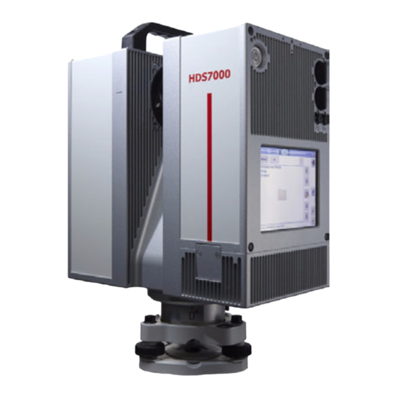
("battery" will be used) c) Tribrach d) Tripod e) Cleaning kit Transport container for HDS7000 accessories g) Transport container for HDS7000 h) Ethernet cable Extension cable for AC power supply / battery charger Power cable for AC power supply k) AC power supply... - Page 12 HDS7000, Description of the System Hardware options • USB plug (32 GB) • HDS7000 scan targets and target accessories • Dolly HDS7000 a) Handle b) Wi-Fi antenna c) ON/OFF button d) Touch screen / Display e) Rotating mirror (Laser exit)
- Page 13 Battery status indicators d) Connector for power supply e) Green LED: Power indicator Red LED: Error LED g) SupD-9 plug: connects battery and charging cradle HDS7000_006 Use the SupD-9 plug only for connecting to the battery. HDS7000, Description of the System...
- Page 14 HDS7000, Description of the System AC power supply / Battery charger a) Power cable for AC power supply b) AC power supply c) Lemo plug (3 pin, female) HDS7000_007...
- Page 15 Extension cable for AC power supply a) Cable b) Connector 3 pin, female c) Connector 3 pin, male Ethernet cable a) Cable b) Connector, 8 pin male c) Ethernet connector GEV228 HDS7000, Description of the System...
-
Page 16: Cabling
0 0 0 2. Pull the battery carefully downwards. HDS7000_008 A battery should always be attached to ensure the optimum weight balance for the HDS7000. If there is no removable battery connected, a warning message appears. - Page 17 Switch off the HDS7000 beforehand or • use the external power supply If the HDS7000 is operated until the battery is completely empty, it has to be recharged immediately. Failure to do this can result in battery damage. Primary use/charging •...
- Page 18 1. Plug the power cable into the battery Charging the battery charger and into an AC plug. 2. Using the HDS7000 power supply cable connect the charging cradle and the battery charger. 3. Place the battery onto the charging cradle.
- Page 19 Charging of the battery takes approximately 1.5 hours. Understand the charging cradle’s LEDs: a) Battery status indicators b) Power indicator LED (green) c) Error LED (red) HDS7000_010 HDS7000, Description of the System...
- Page 20 100% charged. Error LED The red LED illuminates if there is a fault in the electricity supply. Please refer to "HDS7000 Battery" in "4 Troubleshooting". Power indicator The green power indicator LED illuminates if the charging cradle is under voltage.
- Page 21 Precautions: To avoid electric shock power cable and power outlet must be grounded. Warning Batteries not recommended by Leica Geosystems may be damaged if charged or discharged. They may burn and explode. Precautions: Only charge and discharge batteries recommended by Leica Geosystems.
-
Page 22: Operate The Hds7000 With The Battery Charger (Ac Power Supply)
HDS7000, Description of the System 1.4.2 Operate the HDS7000 with the Battery Charger (AC Power Supply) H D S7 00 0 Operate the HDS7000 with the battery charger a) Power cable for AC power supply b) AC power supply c) Power cable to the HDS7000 HDS7000_011 1. - Page 23 Protect the product against humidity. If the product becomes humid, it must not be used! Danger Death or serious injury can occur if unit is not connected to ground. Precautions: To avoid electric shock power cable and power outlet must be grounded. HDS7000, Description of the System...
-
Page 24: Usb Ports
USB plug d) USB memory stick HDS7000_012 USB memory sticks and USB plugs that belong to the HDS7000 should always be attached to the respective USB ports P1 and P2 to prevent dirt and moisture to enter the scanner. - Page 25 Caution Eject the USB memory sticks by pushing the corresponding buttons before removing them. Do not remove the USB memory sticks as long as the symbols are displayed. HDS7000, Description of the System...
-
Page 26: Field Of View (Fov)
HDS7000, Description of the System Field of View (FOV) Field of view The HDS7000 has a rotating mirror system that covers a 360 x 320 degree field of view. 0 0 0 0 0 0 HDS7000_013... -
Page 27: Hds Cyclone Software Suite
Cyclone • Publisher: allows users to publish point cloud data to a panoramic viewing format which can be posted to the Web. Users can then view this data using the Internet Explorer plug-in Leica TruView. HDS7000, Description of the System... - Page 28 • Download: Cyclone Principles Software, as well as important Support documentation, can be down- loaded from the Leica Geosystems HDS Website (http://www.leica-geosystems.com/hds/en/27054.htm). The User must create an account before the download section is accessible. • Installation: You must use a Windows account with administrator privileges to install or...
- Page 29 HDS7000, Description of the System...
-
Page 30: Setting Up The Instrument
HDS7000, Setting Up the Instrument Setting Up the Instrument General Information Use the tripod The instrument should always be set up on its tripod. Using the tripod specified for the scanning system guarantees maximum stability during scanning operations. Always set up the instrument on its tripod. Do not set up the instrument directly on the ground for scanning operations. -
Page 31: Scanner Setup On Tripod
Scanner Setup on Tripod Setup step-by-step 0 0 0 HDS7000_014 HDS7000, Setting Up the Instrument... - Page 32 When placing the instrument on the tribrach, align the legs of the scanner’s table stand with the foot screws of the tribrach. It is recommended to setup the HDS7000 horizontally by using the tripod screws. Subsequently the established horizontation can be refined using the integrated electronic level.
-
Page 33: Setup Over A Benchmark With The Internal Laser Plummet
Description This topic describes an instrument setup over a marked ground point using the laser plummet. Geo-referencing of the HDS7000 is established by setting up over a known or assumed control point, with optional reference target measurement to set the azimuth direction, and establishing a local or global coordinate system. - Page 34 HDS7000, Setting Up the Instrument Setup step-by-step 0 0 0 HDS7000_015 Shield the instrument from direct sunlight and avoid uneven temperatures around the instrument. 1. Extend the tripod legs to allow for a comfortable working posture (a). Position the tripod approximately over the marked ground point, centring it as well as possible (b).
- Page 35 7. By using the electronic level (Level) turn the tribrach footscrews (h) to precisely level the instrument. 8. Centre the instrument precisely over the ground point (i) by shifting the tribrach on the tripod plate. 9. Repeat steps 7. and 8. until the required accuracy is achieved. HDS7000, Setting Up the Instrument...
-
Page 36: Instrument Height
HDS7000, Setting Up the Instrument Instrument Height To get an accurate measurement, hold Measure instru- the end of measurement tape with your ment height foot on benchmark. Now expand the 0 0 0 measurement tape and read height using bottom line on unit as shown. -
Page 37: Setting Up The Instrument With The Dolly
6. Secure the tripod legs with the respec- tive securing strap of each set The dolly is available as an optional accessory and is not part of the standard scope of delivery. HDS7000_017 HDS7000, Setting Up the Instrument... -
Page 38: Scanning
HDS7000, Scanning Scanning Switching the System On/Off Switch on proce- 1. Setup the instrument as desired. Refer to chapter "2 Setting Up the Instrument" dure for more information. 2. Check that the lens is clean. 3. Press and hold the ON/OFF button for a minimum of 0.3 seconds. -
Page 39: Preparations
• Have at least three targets per scan • For best results use the 6" Leica grey and white tilt-and-turn targets. • For printed paper targets use white paper and laser printers only. Test your print- outs prior to using them in the field. - Page 40 • The recommended distance of the targets to the scanner depends on the scan resolution. • Ensure that the HDS7000 is within the recommended distance to the targets. Resolution Recommended target distance at angle of incident approx. 90° 1 -10 m...
- Page 41 Target distance <45° HDS7000_018 HDS7000, Scanning...
-
Page 42: Ambient Conditions
HDS7000, Scanning Ambient Conditions Unfavorable • Highly reflective (polished metal, gloss paint) surfaces • Highly absorbent (black) • Translucent (clear glass) Color or powder these surfaces before scanning. • Rain, snow or fog cause poor measurements, so it is not possible to... - Page 43 Soiling at the glass pane of the mirror, such as a layer of dust, condensed water or fingerprints, causes considerable measuring errors. Before initiating the scanning process check if there is enough space on the Memory capacity internal flash disk (30 – 60 GB per day, depending on your planning). HDS7000, Scanning...
- Page 44 HDS7000, Scanning Others Keep field notes containing: • Target positions relative to the instrument. • Position of the instrument within the measured area (such as the factory or shed plan). Cyclone -SCAN Cyclone SCAN software controls scanning operations with the instrument and allows point cloud visualization and measurement.
-
Page 45: Onboard Controls
Onboard Controls To control the HDS7000 via the touch Stylus for touch screen screen a special stylus is required which is located directly at the scanner in the designated slot and can be removed for operation. HDS7000_019 • Clicking on a symbol or button opens a menu or executes a command. - Page 46 HDS7000, Scanning Overview display a) Status bar b) Screen area c) Command bar HDS7000_020 Element Description Status bar Shows current status information for the instrument. Screen area Working area of the screen. Command bar Shows available commands of the current screen.
- Page 47 Shows scanner status and IP address. In the tooltip information about firmware version, DHCP status and remaining time until next calibration is listed. Shows current date and time. Status of the battery, tooltip shows exact capacity. Scanner is connected to external power. HDS7000, Scanning...
- Page 48 HDS7000, Scanning Element Description Internal flash disk capacity, tooltip shows used and free disk space. A USB memory stick is connected to upper USB port P1 or bottom USB port P2. It can be ejected by clicking the respective icon.
- Page 49 Element Description Shows the current menu, for example "Home". When an numeric or Overview user alphanumeric input field input is selected with the stylus, a virtual keyboard opens offering letters, numbers and special characters. HDS7000, Scanning...
- Page 50 HDS7000, Scanning Element Description Quit keyboard mode and return to previous menu. Toggle between upper and lower case. Toggle between alphanumeric and numeric/special characters. Delete all in the input field. Backspace. Confirm and return to previous menu.
-
Page 51: Main Menu
Main Menu The main menu is Description displayed after the system boot process. Icon Description Scanning Offers access to all commands for scanner operation control. HDS7000, Scanning... - Page 52 HDS7000, Scanning Icon Description Scans Offers access to all commands for scan management. Help Offers access to the online help menu. Brightness Decrease or increase the brightness of the screen. Status Show current scanner status. Settings Offers access to the scanner settings.
-
Page 53: Scanning
Scanning Access Select Main Menu, Scanning Description In the Scanning menu all commands for scanner setup and scan parameters are available. HDS7000, Scanning... - Page 54 HDS7000, Scanning Scanning screen Icon Description Level Open the Level menu to control the digital bubble and the laser plummet.
- Page 55 Open the setup menu for scanning in 2D profiling mode. Panorama Open the menu for panoramic image acquisition with an external camera. 1-TO Open the One Target Orientation menu for scanner setup and orientation by known points. Exit Close and return to previous menu. HDS7000, Scanning...
- Page 56 HDS7000, Scanning Icon Description Setup Setup the parameters for a predefined scanning.
-
Page 57: Level
3.6.1 Level Access Select Main Menu, Level Description In the Level menu the digital bubble and the laser plummet can be controlled. Level screen HDS7000, Scanning... - Page 58 HDS7000, Scanning Icon Description Rotate 180° Rotate the scanner horizontally by 180°. Justify Turn the scanner horizontally to 0° and 180° and then calculate the tilt sensor's zero point (X0,Y0). Plummet Turn the laser plummet on/off. By default the laser plummet is off after system boot.
-
Page 59: Start Predefined Scan
Select Main Menu, Scan predefined Description In the menu Scan predefined a scan is started with predefined settings as defined in the menu Setup (refer to "3.6.7 Setup a Predefined Scan"). The button works like a quick-scan-button without any further configuration needed. HDS7000, Scanning... -
Page 60: Scan With User Defined Settings
HDS7000, Scanning 3.6.3 Scan with User Defined Settings Access Select Main Menu, Scan Description In the Scan menu all parameters for a user defined scan can be set. Scan screen... - Page 61 Select the scan quality by pressing the +/- buttons or the slider. Level Enable or disable the electronic level to monitor scanner move- ment during the scan process and overall inclination of the instrument. Camera Select optional camera. Setting is off by default. HDS7000, Scanning...
- Page 62 HDS7000, Scanning Scanning resolu- Resolution Increments Point Pixel/ ZFS file size Ideal object tion level (Hz / V) spacing at 360° (compressed) distance 10 m 0.288° / 50.3 mm 1250 ca. 4 MB > 0.5 m Preview 0.288° 0.144° / 25.1 mm...
- Page 63 63.5 KHz 31.75 KHz 0:52 min 1:44 min 3:22 min 6:44 min High 10000 50 rps 25 rps 12.5 rps 6.25 rps 508 KHz 254 KHz 127 KHz 63.5 KHz 1:44 min 3:22 min 6:44 min 13:28 min HDS7000, Scanning...
- Page 64 HDS7000, Scanning Resolution Pixel/ Normal High Premium level 360° quality quality quality quality Super 20000 50 rps 25 rps 12.5 rps 6.25 rps 1.016 MHz 508 KHz 254 KHz 127 KHz High 3:28 min 6:44 min 13:28 min 26:56 min...
- Page 65 Advanced scan By clicking Advanced an advanced scan menu with additional settings can be screen accessed. HDS7000, Scanning...
- Page 66 HDS7000, Scanning Field Description Comment Enter additional information to be stored in the scan header. Operator Enter operator details to be stored in the scan header. Horizontal Define the left and right limit of the horizontal scan area. Vertical Define the bottom and top limit of the vertical scan area or select a predefined scan area.
- Page 67 Left 20° - 180° Right 180° - 340° 0 0 0 HDS7000_022 HDS7000_023 Top 100° - 260° User With this option selected, the user can enter the bottom and top limit in the designated fields. 0 0 0 HDS7000_024 HDS7000, Scanning...
-
Page 68: Profile Scanning
HDS7000, Scanning 3.6.4 Profile Scanning Access Select Main Menu, Profiler Description In the menu Profiler the settings for the 2D profiling mode can be controlled. In profile scanning the horizontal motor is blocked and only the vertical mirror rotates. In this mode the scanner typically is mounted on a moving vehicle and the horizontal rotation is replaced by a forward motion. -
Page 69: Panorama
3.6.5 Panorama Access Select Main Menu, Panorama Description In the menu Panorama panoramic images with an external camera can be created. Panorama screen HDS7000, Scanning... - Page 70 HDS7000, Scanning Requires external software (e.g. PTGui) to stitch single images to a full panoramic image.
-
Page 71: One Target Orientation (1-To)
In the 1-TO menu the settings of the One Target Orientation can be made. The user can enter coordinates, heights and names of a known scanner position and a known target position for an offline calculation of scanner setup and orientation by known points. HDS7000, Scanning... - Page 72 HDS7000, Scanning 1-TO screen...
-
Page 73: Setup A Predefined Scan
In the Setup menu the settings for the quick-scan-button (refer to "3.6.2 Start Predefined Scan") can be defined. The settings are the same as for a user-defined scan (refer to "3.6.3 Scan with User Defined Settings"). In addition the parameters for the quick-scan-button can be protected by a password here. HDS7000, Scanning... -
Page 74: Scans
HDS7000, Scanning Scans Access Select Main Menu, Scans Description In the Scans menu all commands for scan management are available such as copy, move, delete and display scans. - Page 75 Scan folder screen Icon Function Internal / USB P1/ USB P2 Select access to internal flash drive or to external USB memory stick. HDS7000, Scanning...
- Page 76 HDS7000, Scanning Icon Function Root folder Go to root folder of selected drive. Up / Down Navigate up or down in the folder list. Go to first / Navigate to the first or last folder in the last list. Expand Expand selected folder.
- Page 77 Switch to disk management to clean up unlinked files and empty folders or to start Check Disk for fixing of logical file system errors. Statistic Switch to the Statictics menu to display the number of scans per day in a selected month. HDS7000, Scanning...
- Page 78 HDS7000, Scanning Scans screen Icon Function Folder Shows the selected folder. Up / Down Navigate up or down in the scan list.
- Page 79 Icon Function Go to first / Navigate to the first or last scan in the list. last View Open view mode and show selected scan on display. HDS7000, Scanning...
- Page 80 HDS7000, Scanning View screen Icon Function Mode Toggle between movement, selection and measure- ment mode.
- Page 81 Undo Undo the last user command for movement, labeling or selection. View Toggle between 2D, bubble and info view. Grid In movement mode display/hide a grid. Zoom in Zoom in to see details of the selected scan. HDS7000, Scanning...
- Page 82 HDS7000, Scanning Icon Function Zoom out Zoom out to get a better overview of the selected scan.
-
Page 83: Help
Help Access Select Main Menu, Help Description In the Help menu online help files and support contacts can be found. HDS7000, Scanning... -
Page 84: Status
HDS7000, Scanning Status Access Select Main Menu, Status Description In the Status menu the current scanner status and potential errors are displayed. Status screen... - Page 85 Icon Function Ignore Confirm error and proceed. Abort Confirm error and abort. Help Open help menu with support contacts. Report Create a report file and store it on USB memory stick if connected. HDS7000, Scanning...
-
Page 86: Settings
HDS7000, Scanning 3.10 Settings Access Select Main Menu, Settings Description In the Settings menu the instrument can be configured by changing settings for language, units, date/time or the IP address. - Page 87 Settings screen Settings marked with “*1” require a scanner restart to take effect. HDS7000, Scanning...
- Page 88 HDS7000, Scanning Field Description Language Select operating language (English, German, Spanish, French, Italian, Japanese, Dutch, Russian, Portuguese, Chinese). Unit Select unit for distances (meter, foot, foot + inch, yard). Date/Time Set local date and time and confirm with “Apply+switchoff”. After confirmation the scanner switches off and must be rebooted.
-
Page 89: Hardware
3.11 Hardware Access Select Main Menu, Hardware Description In the Hardware menu information about internal and external hardware compo- nents is displayed. HDS7000, Scanning... - Page 90 HDS7000, Scanning Hardware screen Icon Function Calib Touch Open touch screen calibration. Level Open the Level menu to control the digital bubble and the laser plummet.
- Page 91 Digi-Cam Detect and check status of an optional digital camera. Check functionally of an optional attached GPS. Motor Check functionality of horizontal and vertical motors. Connector Test input and output signals of lemo connectors P3 and P4. HDS7000, Scanning...
-
Page 92: Connections
IP address. The HDS7000 supports DHCP (Dynamic Host Configuration Protocol). If the auto- matic reference to an IP address is set at the client (DHCP client), the HDS7000 can be included in any network without further configuration. - Page 93 If the HDS7000 is connected by an Ethernet cable only to a notebook, without a wider network structure, then the HDS7000 is a DHCP server. The HDS7000 assigns a dynamic IP address to the notebook/PC on start-up. If there is no DHCP the user must enter the IP address and netmask.
-
Page 94: Connecting The Hds7000 To A Network By Cable
HDS7000, Scanning 3.12.1 Connecting the HDS7000 to a Network by Cable Access Select Main Menu, Settings Description In the Settings menu enable the DHCP Client option for a connection to a network. - Page 95 Connecting by 1. Connect the HDS7000 with the attached Ethernet cable to a hub/switch on the cable desired network. 2. Settings on the HDS7000: • Switch on the HDS7000 (press the ON/OFF button for 0.3 sec). • Go to Main Menu, Settings and enable DHCP Client.
-
Page 96: Connecting The Hds7000 To A Notebook By Cable
HDS7000, Scanning 3.12.2 Connecting the HDS7000 to a Notebook by Cable Access Select Main Menu, Settings Description In the Settings menu enable the DHCP Server option for a connection to a notebook. - Page 97 • Enter the IP address directly at the FTP client. The scan files on the HDS7000’s hard disk are listed in their subfolders in the web browser/FTP client. When using the web browser a preview of every scan is shown.
- Page 98 HDS7000, Scanning • The firewall of the notebook should be deactivated to avoid disturbing the connection to the scanner. • The proxy settings of the web browser should be deactivated or an exception for the web page must be declared.
-
Page 99: Connecting The Hds7000 By Wi-Fi
2. Select Wireless Network Connections. 3. In the Wireless Network Connections list the HDS7000 is listed as hds7000- xxxx with xxxx = serial number. If scanner is not listed select Refresh network list, after some seconds the system automatically will find the HDS7000. -
Page 100: Operating The Hds7000 Using A Web Browser
3.13 Operating the HDS7000 using a Web Browser Start page The HDS7000 can be operated via Ethernet connection or via Wi-Fi in a local network directly using a web browser. Enter the IP address of the HDS7000 into the address field of your web browser. - Page 101 Further shortcuts for menu points include: • /home • /config • /report • /info (password protected) • /backlight • /scan • /debug • /profiler • /scan/predefined • /firmware • /statistic • /scanmanagement • /camera • /error • /status • /systemtest • /error/help HDS7000, Scanning...
- Page 102 HDS7000, Scanning Scan menu in web For example: http//172.20.0.100/info browser The settings for the web browser scan interface are the same as for the interface of the onboard display. Refer to chapter "3.6.3 Scan with User Defined Settings" for details.
- Page 103 HDS7000, Scanning...
-
Page 104: Troubleshooting
-10°C. the activity helps warm the HDS7000. Instrument too The instrument is operated Put the HDS7000 in a cool and warm. at a temperature higher shady place, leave it powered in than +45°C. standby mode only. - Page 105 Dirt on the touch screen. Turn off the instrument and not work correctly. clean control panel with mild cleaning supplies and a soft tissue. HDS7000 Battery Problem Possible Cause(s) Suggested Remedies When switching on the Capacity of battery is Recharge or change battery.
- Page 106 HDS7000, Troubleshooting Problem Possible Cause(s) Suggested Remedies Internal battery is no At the end of its life time the longer charging. internal battery has lost most of its capacity. The battery needs to be replaced. HDS7000 battery Problem Possible Cause(s)
- Page 107 The report file procedure explains how to create a report file with the user interface dure of your HDS7000 instrument in case of problems with the scanner. To create a report file, follow the steps described below: 1. Go to Main Menu, Status, Report to create a report file.
-
Page 108: Care And Transport
HDS7000, Care and Transport Care and Transport Check & Adjust Caution Units that are exposed to high mechanical forces, e.g. through frequent transport or rough handling, it is recommended to carry out a check and adjust twice a year by... -
Page 109: Transport
Always carry the product in its transport container and secure it. Shipping When transporting the product by rail, air or sea, always use the complete original Leica Geosystems packaging, transport container and cardboard box, or its equiva- lent, to protect against shock and vibration. Shipping, transport... -
Page 110: Storage
HDS7000, Care and Transport Storage Product Respect the temperature limits when storing the equipment, particularly in summer if the equipment is inside a vehicle. Refer to "7 Technical Data" for information about temperature limits. Field adjustment After long periods of storage, inspect the field adjustment parameters given in this user manual before using the product. -
Page 111: Cleaning And Drying
+40°C / +104°F and clean them. Do not repack until everything is completely dry. Always close the transport container when using in the field. Cables and plugs Keep plugs clean and dry. Blow away any dirt lodged in the plugs of the connecting cables. HDS7000, Care and Transport... -
Page 112: Window Cleaning Procedure
HDS7000, Care and Transport Window Cleaning Procedure General The HDS7000 scanning window must be kept clean. The instructions must be followed as described in this chapter to clean the scanner mirror. Warning Direct intrabeam viewing is always hazardous. Precautions: Before cleaning windows, ensure the instrument is switched off. - Page 113 Do not touch the side of the paper that is used for cleaning with your fingers. • Do not reuse tissues that have been used before. • Only use non-fuzzy lens tissues. • Do not use air from the pneumatic power system as this is always slightly oily! HDS7000, Care and Transport...
-
Page 114: Adjustment Of The Circular Level
HDS7000, Care and Transport Adjustment of the Circular Level On the tribrach step-by-step HDS7000_027 Step Description Level up the tribrach together with the instrument in advance using the electronic level, assuming that the instrument is correctly adjusted. Remove the instrument from the tribrach. -
Page 115: Service Of The Tripod
Moderately tighten the allen screws (1) with the allen key supplied with the tripod. Tighten articulated joints just enough to keep the tripod legs open when lifting the tripod off the ground (2). Tighten the allen screws of the tripod legs (3). HDS7000, Care and Transport... -
Page 116: Safety Directions
HDS7000, Safety Directions Safety Directions General Description Description The following directions should enable the person responsible for the product, and the person who actually uses the equipment, to anticipate and avoid operational hazards. The person responsible for the product must ensure that all users understand these... -
Page 117: Intended Use
Opening the product using tools, for example screwdriver, unless this is specifi- cally permitted for certain functions. • Modification or conversion of the product. • Use after misappropriation. • Use of products with obviously recognizable damages or defects. HDS7000, Safety Directions... - Page 118 HDS7000, Safety Directions • Use with accessories from other manufacturers without the prior explicit approval of Leica Geosystems. • Inadequate safeguards at the surveying site, for example when measuring on roads. • Deliberate dazzling of third parties. • Controlling of machines, moving objects or similar monitoring application without additional control- and safety installations.
-
Page 119: Limits Of Use
Danger Local safety authorities and safety experts must be contacted before working in hazardous areas, or in close proximity to electrical installations or similar situations by the person in charge of the product. HDS7000, Safety Directions... -
Page 120: Responsibilities
HDS7000, Safety Directions Responsibilities Leica Geosystems AG, Heinrich-Wild-Strasse, CH-9435 Heerbrugg, Switzerland, here- inafter referred to as Leica Geosystems, is responsible for supplying the product, including the user manual and original accessories, in a completely safe condition. Manufacturers of The manufacturers of non Leica Geosystems accessories for the product are respon-... -
Page 121: Hazards Of Use
Caution During the operation of the product there is a hazard of squeezing extremities or entanglement of hairs and/or clothes by rotating parts. Precautions: Keep a safe distance of the rotating parts. HDS7000, Safety Directions... - Page 122 HDS7000, Safety Directions Caution With the remote control of products, it is possible that extraneous targets will be picked out and measured. Precautions: When measuring in remote control mode, always check your results for plausibility. Danger Because of the risk of electrocution, it is very dangerous to use poles and extensions in the vicinity of electrical installations such as power cables or electrical railways.
- Page 123 If computers intended for use indoors are used in the field there is a danger of elec- tric shock. Precautions: Adhere to the instructions given by the computer manufacturer with regard to field use in conjunction with Leica Geosystems products. HDS7000, Safety Directions...
- Page 124 Only Leica Geosystems authorised service workshops are entitled to repair these products. Warning Using a battery charger not recommended by Leica Geosystems can destroy the batteries. This can cause fire or explosions. Precautions: Only use chargers recommended by Leica Geosystems to charge the batteries.
- Page 125 Touching live components Using the product after incorrect attempts were made to carry out repairs. Precautions: Do not open the product. Only Leica Geosystems authorised service workshops are entitled to repair these products. Warning Batteries not recommended by Leica Geosystems may be damaged if charged or discharged.
- Page 126 HDS7000, Safety Directions Danger If unit is not connected to ground, death or serious injury can occur. Precautions: To avoid electric shock power cable and outlet must be grounded. Warning High mechanical stress, high ambient temperatures or immersion into fluids can cause leackage, fire or explosions of the batteries.
- Page 127 Avoid causing sparks when dealing with cables and electrical equipment, and beware of electrostatic discharges. Avoid short-circuits. Corrosive hazard: Battery acid is highly corrosive. Precautions: Wear protective gloves and eye protection. Do not tilt battery, acid can escape from the degassing openings or vents. HDS7000, Safety Directions...
- Page 128 Connect the battery to the battery charger only when the charger is turned off. Fire, smoking, and sparking near the battery are not allowed. Warning If charged or discharged, batteries not recommended by Leica Geosystems may be damaged. They may burn and explode. Precautions:...
- Page 129 Always prevent access to the product by unauthorised personnel. Product specific treatment and waste management information can be downloaded from the Leica Geosystems home page at http://www.leica-geosystems.com/treatment or received from your Leica Geosystems dealer.
-
Page 130: Laser Classification Scanner, Invisible Laser
HDS7000, Safety Directions Laser Classification Scanner, Invisible Laser General The EDM module incorporated into the product produces an invisible laser beam which emerges from the windows. The laser product described in this section is classified as laser class 1 in accordance with: •... - Page 131 Complies with 21 CFR 1040.10 and 1040.11 except for including interference that may cause undesired operation. deviation pursant to LaserNotice No. 50, dated June 24, 2007 Class 1 Laser Product according to IEC 60825-1 ( 2007 - 03 ) HDS7000_028 a) Laser beam HDS7000, Safety Directions...
-
Page 132: Electromagnetic Compatibility Emc
Warning Electromagnetic radiation can cause disturbances in other equipment. Although the product meets the strict regulations and standards which are in force in this respect, Leica Geosystems cannot completely exclude the possibility that other equipment may be disturbed. Caution There is a risk that disturbances may be caused in other equipment if the product is... - Page 133 Although the product meets the strict regulations and standards which are in force in this respect, Leica Geosystems cannot completely exclude the possibility that the product may be disturbed by very intense electromagnetic radiation, for example, near radio transmitters, two-way radios or diesel generators.
- Page 134 Although the product meets in combination with radio or digital cellular phone devices recommended by Leica Geosystems the strict regulations and standards which are in force in this respect, Leica Geosystems cannot completely exclude the possibility that other equipment may be disturbed or that humans or animals may be affected.
-
Page 135: Fcc Statement, Applicable In U
FCC Statement, Applicable in U.S. Applicability The grayed paragraph below is only applicable for products of the HDS7000 System without radio, digital cellular phone devices or Bluetooth. Warning This equipment has been tested and found to comply with the limits for a Class B digital device, pursuant to part 15 of the FCC rules. - Page 136 HDS7000, Safety Directions Warning Changes or modifications not expressly approved by Leica Geosystems for compli- ance could void the user's authority to operate the equipment. Labelling This device contains FCC-ID: M4Y-AG623G2 Art.No.: S.No.: Type: HDS7000 HDS7000 a transmitter: 785833 ..
- Page 137 This device complies with part 15 of the FCC Rules. Operation is subject to the following two conditions: (1) This device may not cause harmful interference, and (2) this device must accept any interference received, including interference that may cause undesired operation. HDS7000_029 HDS7000, Safety Directions...
- Page 138 HDS7000, Safety Directions Labelling battery Type: Li-lon Battery Art.No.: S.No.: 785835 ..Zoller+Fröhlich GmbH D-88239 Wangen im Allgäu Nominal / Charge Voltage: 14.4V / 16.8A Energy / Capacity: 2x70.56Wh, 4.9 Ah Manufactured: ..
- Page 139 HDS7000, Safety Directions...
-
Page 140: Technical Data
HDS7000, Technical Data Technical Data General Technical Data of the Instrument Instrument Compact, phase-based, dual-axis compensated, ultra-high speed laser scanner, with survey-grade accuracy, range, field-of-view and laser plummet. User interface Onboard touch panel, notebook PC or PDA Scanner drive Servo motor... -
Page 141: Laser Scanning System
Gray 37% White 80% 0.5 mm rms 0.4 mm rms 0.3 mm rms 10 m 1.0 mm rms 0.6 mm rms 0.5 mm rms 25 m 2.7 mm rms 1.2 mm rms 0.8 mm rms 50 m HDS7000, Technical Data... - Page 142 HDS7000, Technical Data Range Black 14% Gray 37% White 80% 10 mm rms 3.8 mm rms 2.0 mm rms 1, 2 100 m Data rate 127000 pts/sec (equivalent to "high resolution, high quality scan), 1 sigma range noise, unfiltered raw data...
- Page 143 (6.25 rps, 12.5 rps, 25 rps, 50 rps). Environmentally protected by shield. Scan motors Direct drive, brushless Angular accuracy 125 μrad / 125 μrad (horizontal / vertical) Angular resolution 3.5 μrad / 7 μrad (horizontal / vertical) HDS7000, Technical Data...
-
Page 144: Miscellaneous
HDS7000, Technical Data Miscellaneous Onboard display Touchscreen control with stylus, full colour graphic display, VGA (640 x 320 pixels) Dual-axis compen- • Selectable on/off sator • Resolution 3.6” • Measurement range ±30’ • Accuracy < 25” Level indicator Electronic bubble in onboard control and software Laser plummet •... -
Page 145: Electrical
• Output voltage: 16.8 V DC • Power status: LEDs indicate charging status and capacity level AC power supply • Input voltage: 100 – 240 V AC, 50 - 60 Hz • Output voltage: 24 V DC HDS7000, Technical Data... -
Page 146: Environmental
HDS7000, Technical Data Environmental Environmental Temperature specifications Type Operating Storage temperature [°C] temperature [°C] HDS7000 -10 to +45 -20 to +50 AC power supply -10 to +45 -20 to +50 Battery -10 to +45 0 to +30 Charging cradle 0 to +40... -
Page 147: Physical
Weight [kg] Weight HDS7000 286 x 170 x 395 AC power supply 167 x 67 x 35 0.54 Battery 88 x 170 x 61 Charging cradle 107 x 170 x 30 0.48 Tilt axis height 285 mm HDS7000, Technical Data... -
Page 148: Accessories
• Notebook PC, tablet PC or PDA • HDS scan targets and target accessories • Service agreement for HDS7000 • Extended warranty for Leica HDS7000 • External camera kit (third party product) • External battery • Tripod, Tripod star •... - Page 149 File System NTFS Cyclone Minimum requirements for modeling are different. Please refer to datasheet for specifications, available at your Leica Geosystems dealer. Notebook PC does not record any data! Data can be transferred automatically after scan process. HDS7000, Technical Data...
-
Page 150: Wi-Fi
HDS7000, Technical Data Wi-Fi Standard: IEEE 802.11b/g Wi-Fi technical Frequency band: 2412 MHz - 2462 MHz (channel 1 - 11) data Output: <20 dBm FCC IC: M4Y-AG623C... -
Page 151: Conformity To National Regulations
FCC Part 15 (applicable in US) Conformity to national regula- • Hereby, Leica Geosystems AG, declares that the HDS7000 is in compliance with tions the essential requirements and other relevant provisions of Directive 1999/5/EC. The declaration of conformity may be consulted at http://www.leica-geosys- tems.com/ce. -
Page 152: International Limited Warranty, Software Licence Agreement
Leica Geosystems. Such software is protected by copy- right and other laws and its use is defined and regulated by the Leica Geosystems Software Licence Agreement, which covers aspects such as, but not limited to, Scope of the Licence, Warranty, Intellectual Property Rights, Limitation of Liability, Exclusion of other Assurances, Governing Law and Place of Jurisdiction. - Page 153 You must not install or use the software unless you have read and accepted the terms and conditions of the Leica Geosystems Software Licence Agreement. Installa- tion or use of the software or any part thereof, is deemed to be an acceptance of all the terms and conditions of such Licence Agreement.
-
Page 154: Index
Instrument height ..........36 Adjustment Of circular level on tribrach ......114 Main menu ............51 Battery ............11, 13 Operate the HDS7000 .........22 Battery status indicators ........20 Optimum weight balance ........16 Best results ............39 Position the HDS7000 .........40 Charging the battery ........... 18 Range ...............141... - Page 155 Targets ............... 39 Temperature Operating ............ 146 Operation/Discharging ........18 Permissible temperature ........ 17 Storage ............146 Tripod, service of ..........115 Unfavorable surfaces .......... 42 Unfavourable weather conditions ......42 Vertical scan range ..........66 HDS7000, Index...
- Page 156 Leica Geosystems AG Heinrich-Wild-Strasse CH-9435 Heerbrugg Switzerland Phone +41 71 727 31 31 www.leica-geosystems.com...
Need help?
Do you have a question about the HDS7000 and is the answer not in the manual?
Questions and answers