Advertisement
Overview
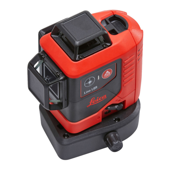
Overview The Leica Lino L6R/L6G is a self-levelling multifunctional laser. It combines the advantage of three 360° line lasers in one tool and an integrated fine adjustment knob. It is a reliable precision laser for any kind of tasks like precise framing, levelling, plumbing, transfering and setting out right angles. It supports you on the job site with six intersection points (front, back, right, left, up, down) which are arranged precisely in 90° to each other. The device can be used indoors and in outdoor situations in case of limited dust and at most splash water effects according to IP54.

- Laser key (on keypad), ON/OFF
- Status LED (on keypad)
- Battery pack
- Levelling lock
- Eccentric fine adjustment knob
- Window of vertical line side
- Tripod thread 1/4"
- Window of vertical line front
- Window of horizontal line
- Keypad
- Power adjustment
There are 2 different types available:
- L6R (red laser)
![]()
- L6G (green laser)
![]()


 On all images in this document only the red laser version is shown.
Technical data
| Description | L6R | L6G |
| Beam direction/fan angle | 2 x Vertical 360°, 1 x Horizontal 360° | |
| Intersection point direction | Up, down, right, left, front, back (90°/180°) | |
| Range/Diameter* | 25 m/50 m (82 ft/164 ft) | 35 m/70 m (115 ft/230 ft) |
| Range/Diameter* with receiver | 70 m/140 m (230 ft/460 ft)** | |
| Levelling accuracy | ±0.2 mm/m = ±2.0 mm @ 10m (±0.002 in/ft = ±0.08 in @ 33ft) | |
| Horizontal/Vertical line accuracy | ±0.3 mm/m (±0.004 in/ft) | |
| Intersection Point accuracy | ±0.2 mm/m (±0.002 in/ft) | |
| Self-levelling range | ± 4° | |
| Self-levelling time | < 3 s | |
| Out-of-level warning | Yes - blink lines every 5 s | |
| Levelling system | Automatic, pendulum lockable | |
| Laser type | 630 - 645 nm, Class 2 (acc. IEC 60825-1) | 510 - 530 nm, Class 2 (acc. IEC 60825-1) |
| Protection class | IP 54 (IEC 60529) dust and splash water | |
| Shock-resistant | 1 m (3.3 ft)*** | |
| Battery type | Lino Li-Ion battery pack 5200 mAh / 18.7 Wh (3 alkaline AA) | |
| Operating time with Li-Ion battery**** | Up to 36h (3 beam) continuous | Up to 11h (3 beam) continuous |
| Operating time with alkaline batteries**** | Up to 25h (3 beam) continuous | Up to 8h (3 beam) continuous |
| Automatic shut-off | Available | |
| Dimensions (L x W x H) | 124 x 107 x 154 mm (4.88 x 4.21 x 6.06 in) | |
| Weight with Li-Ion battery | 781 g (1.71 lbs) | |
| Operating temperature | -10...+50°C (+14...+122°F) | |
| Storage temperature | -25...+70°C (-13...+158°F) | |
| Laser line width at 5m (16.4 ft) distance | < 2 mm (<0.08 in) | |
| Tripod thread | 1/4'' (+ 5/8'' with adapter) | |
| Pulse power for receiver | Yes, auto | |
* depending on lighting conditions
** with Leica RGR 200 receiver
*** accuracy > ± 0.2mm/m (> ± 0.002in/ft), check required
**** @20°C / 68°F
Instrument Set-up
Introduction
 The safety instructions (see Safety Instructions) and the user manual should be read through carefully before the product is used for the first time.
The person responsible for the product must ensure that all users understand these directions and adhere to them.
The symbols used have the following meanings:

Indicates a potentially hazardous situation or an unintended use which, if not avoided, will result in death or serious injury.

Indicates a potentially hazardous situation or an unintended use which, if not avoided, may result in minor injury and/or appreciable material, financial and environmental damage.
Important paragraphs which must be adhered to in practice as they enable the product to be used in a technically correct and efficient manner.
Levelling lock
Levelling unlocked
In the unlocked position the instrument automatically levels itself within the specified inclination range. (See Technical data)

Levelling locked
Turn the levelling lock in order to transport or tilt the instrument beyond the self-levelling range. When locked, the pendulum is fixed and the selflevelling function is deactivated. In this case the laser blinks every 5 sec.

Laser receiver
To be able to detect the laser lines over long distances or in unfavourable lighting conditions, a laser receiver can be used.
We recommend the Leica RGR200 laser receiver.

The Lino is powered by XRANGE technology and therefore automatically detected by the receiver.
Li-Ion battery
Charge Li-Ion battery

Charge the Li-Ion battery at +5°C to +45°C (+41°F to +113°F) before using it for the first time. While charging, the instrument may heat up. This is normal and should not affect the instrument´s lifespan or performance. At the recommended storage temperature of -20°C to +30°C (-4°F to +86°F), batteries containing a 50% to 100% charge can be stored up to 1 year. After this storage period the batteries must be recharged.
Connecting the charger using the wrong adapter may cause serious damage to the instrument. Any damage caused by misuse is not covered by warranty. Use only Leica-approved chargers, batteries and cables. Unapproved chargers or cables can cause the battery to explode or damage the instrument.
Insert Li-Ion battery
Insert the battery-pack by pressing it down and then tilting it towards the housing as shown until it snaps in.

Li-Ion status LED
The function of the Li-Ion status LED is indicated by the 3rd number in the 10-digit serial number on the type label of the Li-Ion battery.

Number 0, 1 or 2:
 | lights green: charging battery |
 | OFF: charging finished / no charging |
Number 3 or higher:
 | blinks green: charging battery |
| lights green: charging finished / no charging |
Alkaline batteries
To ensure a reliable use, we recommend using high quality Alkaline batteries.
Insert Alkaline batteries

Insert Alkaline batteries in the battery-pack.
Insert the battery-pack

Insert the battery-pack by pressing it down and then tilting it towards the housing as shown until it snaps in.
Operations
Switching ON/OFF

Auto power-off Place the lock switch to the unlocked position (see Levelling lock). To activate auto power-off after 30 min operation press and hold the ON button at start for 5 sec. The status LED blinks 3 times in green colour. To deactivate it again repeat the described steps until the status LED blinks 3 times in red colour.

Functions
Laser on/Vertical and horizontal mode

All on mode*

Horizontal mode

Layout mode

Vertical side mode

Check if self-levelling is required and correspondingly activated. (See Levelling lock for details)
* In very hot environments it can be that maximum two lines work simultaneously (see Message Codes).
Vertical front mode

Activate levelling lock and press ON for tilt applications.

Switching line intensity

- 1x: Power reduction -25%, smaller line width.
- 2x: Power reduction -50%, smallest line width.
- 3x: Full power 100%, maximum range (default).
Saving operating mode
Place the lock switch to the unlocked position (see Levelling ating mode, press and hold the ON and power adjustment button during operation for 2 sec. The status LED blinks 3 times in green colour. The instrument has stored the function and line intensity to the memory and as the new default mode. To reset the function and line intensity to factory settings, press and hold the ON and power adjustment button during operation for 5 sec and wait until the status LED blinks 3 times in red colour.

2 sec = save actual function and line intensity

5 sec = reset to factory settings
How to use the smart adapters
Setup device to adapter

Snap the device on the Twist 250 adapter.
Alignment of vertical laser lines

Turn the device 250° to adjust the vertical line. Use the side knob and turn the device around the vertical intersection / plumb point within ± 10°.
Alignment of horizontal laser lines

Turn the adjustment knob of UAL130 to fine adjust the horizontal line to the desired reference level.
Different fixing applications


Message Codes
| Laser | LED | Cause | Correction |
| ON/OFF | lights red | Instrument has low power | Charge Li-Ion battery or change Alkaline batteries |
| ON/blinks | lights orange | Instrument is close to temperature limit. In very hot environments it can be that maximum two lines work simultaneously. | Cool down instrument |
| OFF | blinks red | Temperature alert | Cool down or heat up instrument |
| blinks | blinks red | Instrument is out of self-levelling range | Place the instrument almost horizontal and self-levelling will start automatically |
| blinks | lights red | Instrument is out of self-levelling range and has low power | Charge Li-Ion battery or change Alkaline batteries |
| blinks every 5 sec | lights red | Levelling lock is activated but instrument has low power | Charge Li-Ion battery or change Alkaline batteries |
| blinks every 5 sec | blinks green | Levelling lock is activated for working without self-levelling |
Accuracy Check
Check the accuracy of your instrument regularly and particularly before important measuring tasks. Check Levelling lock before checking the accuracy.
Levelling
Checking the accuracy of the levelling

Set the instrument on a tripod half-way between two walls (A+B) that are approx. 5 m apart. Place the lock switch in the "Unlocked" position (see Levelling lock). Direct the instrument at wall A and switch on the instrument. Activate the horizontal laser line or laser point and mark the position of the line or the point on wall (A1). Rotate the instrument by 180° and mark the horizontal laser line or the laser point in exactly the same way on wall (B1).

Then place the instrument at the same elevation as close as possible to wall A and again mark the horizontal laser line or the laser point on wall A (A2). Rotate the instrument by 180° again and mark the laser on wall B (B2). Measure the distances of the marked points A1-A2 and B1-B2. Calculate the difference of the two measurements.
(A1 - A2) - (B1 - B2)| <=2 mm
If the difference does not exceed 2 mm, then the instrument is within tolerance.
Should your instrument be outside of the specified tolerance, please contact a local dealer or an authorised Leica Geosystems distributor.
Vertical and horizontal line
Checking the accuracy of the horizontal line

Place the lock switch in the "Unlocked" position (see Levelling lock). Position the instrument approx. 5 m away from the wall. Direct the instrument at the wall and switch on. Activate the laser line and mark the intersection point of laser crosshairs on the wall. Swivel the instrument to the right and then to the left. Observe the vertical deviation of the horizontal line from the marking. If the difference does not exceed 3 mm, then the instrument is within tolerance.
Checking the accuracy of the vertical line

Place the lock switch in the "Unlocked" position (see Levelling lock). As a reference, use a plumbbob and attach it as close as possible to an approx. 3 m high wall. Position the instrument at a distance of approx. 1.5 m from the wall at an elevation of approx. 1.5 m. Direct the instrument at the wall and switch on. Rotate the instrument and align it with the bottom of the plumb line. Now read off the maximum deviation of the laser line from the top of the plumb line. If the difference does not exceed 2 mm, then the instrument is within tolerance.
Should your instrument be outside of the specified tolerance, please contact a local dealer or an authorised Leica Geosystems distributor.
Vertical plumb/intersection points
Checking the accuracy of the upper plumb intersection point:

Place the lock switch in the "Unlocked" position (see Levelling lock). Set up the laser on its tripod or wall mount bracket near point A1 at a minimum distance of 1.5 m from point B1. The horizontal laser is aligned in direction 1. Mark the laser points A1 and B1 with a pin. Rotate the instrument by 180° so that it points in the opposite direction 2 to direction 1. Adjust the instrument so that the laser beam hits point A1 exactly. If point B2 is no further than 2 mm away from point B1, then the instrument is within tolerance.
Checking the accuracy of the lower plumb intersection point:

Place the lock switch in the "Unlocked" position (see Levelling lock). Set up the laser on its tripod or wall mount bracket near point A1 at a minimum distance of 1.5 m from point B1. The horizontal laser is aligned in direction 1. Mark the laser points A1 and B1 with a pin. Rotate the instrument by 180° so that it points in the opposite direction 2 to direction 1. Adjust the instrument so that the laser beam hits point A1 exactly. If point B2 is no further than 2 mm away from point B1, then the instrument is within tolerance.
Should your instrument be outside of the specified tolerance, please contact a local dealer or an authorised Leica Geosystems distributor.
Perpendicularity horizontal intersection points

Place lock switch in "Unlocked" position (see elling lock). Mark a reference point (P1) approx. 5m from the walls and position the lower plumb intersection point exactly on it. Align the cross hair to the left wall and mark the intersection point (a1) approx. on the same height like P1 to the wall. Shortly after mark the right-hand perpendicular beam (b1) on the front wall.

Then rotate the device exactly 90° clockwise around the plumb intersection point P1 and position the left-hand perpendicular intersection beam to the existing reference point a1. Make sure that the lower plumb intersection point is still exactly on the reference P1. Check afterwards the new reference point b2 with the old reference b1 on the front wall. The deviation between the two points may be max. 3mm. Mark the new position of the right-hand perpendicular beam to the right wall with c1.
Should your instrument be outside of the specified tolerance, please contact a local dealer or an authorised Leica Geosystems distributor.

Afterwards, turn the device exactly 180° around the plumb intersection point P1 and position the right-hand perpendicular beam to the existing reference point a1. Make sure that the lower plumb intersection point is still exactly on the reference P1. Then mark the left-hand beam to the right wall and mark it with c2. Finally measure the difference between the former reference point c1 and the new point c2. The deviation may be max. 3mm between these two points.
Should your instrument be outside of the specified tolerance, please contact a local dealer or an authorised Leica Geosystems distributor.
Care
Never immerse the device in water. Wipe off dirt with a damp soft cloth. Never use aggressive cleaning agents or solvents. Treat the instrument with the same care that you would apply to binoculars or a camera. Dropping or violent shaking of the instrument may damage it. Check the instrument for any damage before using it. Check the levelling accuracy of the instrument regularly. To warranty the best precision and visibility please clean the optics of your device regularly. Therefore blow off the dust from the glasses without touching the optics with your fingers. If necessary use a damp soft cloth and a little bit of pure alcohol. To avoid wrong measurements also clean your adapters regularly. This could be done also by the proposed recommendation. Especially the interface between the adapter and device should always be clean to enable easy rotation. To clean the magnetic surface you could use compressed air or modelling clay. If the equipment get wet always dry it (max. 70°C/158°F) before repacking it into the case.

Documents / ResourcesDownload manual
Here you can download full pdf version of manual, it may contain additional safety instructions, warranty information, FCC rules, etc.
Advertisement


Need help?
Do you have a question about the Lino L6R and is the answer not in the manual?
Questions and answers