Leica 3D Disto User Manual
Hide thumbs
Also See for Leica 3D Disto:
- User manual (219 pages) ,
- Quick start manual (18 pages) ,
- User manual (90 pages)

Related Manuals for Leica Leica 3D Disto


Summary of Contents for Leica Leica 3D Disto
- Page 1 Leica 3D Disto User Manual Version 4.0 English 1.800.561.8187 information@itm.com www. .com...
- Page 2 Refer to the following resources for all 3D Disto documentation/software: • Leica USB memory stick • https://myworld.leica-geosystems.com Leica Geosystems On the last page of this manual, you can find the address of Leica Geosystems head- Address Book quarters. For a list of regional contacts, please visit www.leica-geosys- tems.com/contacts.
- Page 3 Service Description myProducts Add all Leica Geosystems products that you and your company own. View detailed information on your products, buy additional options or Customer Care Packages (CCPs), update your prod- ucts with the latest software and keep up-to-date with the latest documentation.
-
Page 4: Table Of Contents
Table of Contents In this manual Chapter Page Safety Directions General Introduction Definition of Use Limits of Use Responsibilities Hazards of Use Laser Classification 1.6.1 General 1.6.2 Integrated Distance Meter Electromagnetic Compatibility EMC FCC Statement, Applicable in U.S. Déclaration FCC, propre aux Etats-Unis Description of the System Overview Container Contents... - Page 5 10.1 Transport 10.2 Storage 10.3 Cleaning and Drying Technical Data 11.1 Technical Data 11.2 Conformity to National Regulations 11.3 Dangerous Goods Regulations Warranty under PROTECT by Leica Geosystems Software Licence Agreement 1.800.561.8187 3D Disto, Table of Contents information@itm.com www. .com...
-
Page 6: Safety Directions
Safety Directions General Introduction Description The following directions enable the person responsible for the product, and the person who actually uses the equipment, to anticipate and avoid operational hazards. The person responsible for the product must ensure that all users understand these directions and adhere to them. -
Page 7: Definition Of Use
• To ensure that it is used in accordance with the instructions. • To be familiar with local regulations relating to safety and accident prevention. • To inform Leica Geosystems immediately if the product and the application becomes unsafe. • To ensure that the national laws, regulations and conditions for the operation of e.g. -
Page 8: Hazards Of Use
Hazards of Use Watch out for erroneous measurement results if the product has been dropped or has CAUTION been misused, modified, stored for long periods or transported. Precautions: Periodically carry out test measurements, particularly after the product has been subjected to abnormal use and before and after important measurements. During dynamic applications, for example stakeout procedures there is a danger of WARNING accidents occurring if the user does not pay attention to the environmental conditions... -
Page 9: Laser Classification
Product-specific treatment and waste management information can be downloaded from the Leica Geosystems home page at http://www.leica- geosystems.com/treatment or received from your Leica Geosystems distributor. Only Leica Geosystems authorised service workshops are entitled to repair these prod- WARNING ucts. Laser Classification 1.6.1... -
Page 10: Integrated Distance Meter
1.6.2 Integrated Distance Meter Integrated Distance The Leica 3D Disto produces a visible laser beam which emerges from the front of the Meter instrument. The laser product described in this section is classified as laser class 2 in accordance with: •... -
Page 11: Electromagnetic Compatibility Emc
WARNING Although the product meets the strict regulations and standards which are in force in this respect, Leica Geosystems cannot completely exclude the possibility that other equipment may be disturbed. The product is a class A product when operated with the internal batteries. In a domestic environment this product may cause radio interference in which case the user may be required to take adequate measures. -
Page 12: Fcc Statement, Applicable In U
Precautions: Although the product meets the strict regulations and standards which are in force in this respect, Leica Geosystems cannot completely exclude the possibility that other equipment can be disturbed or that humans or animals can be affected. • Do not operate the product with radio or digital cellular phone devices in the vicinity of filling stations or chemical installations, or in other areas where an explosion hazard exists. -
Page 13: Déclaration Fcc, Propre Aux Etats-Unis
June 24, 2007 IEC 60285-1:2014 λ=620-690nm Pav<1mW tp<1ns SWISS Technology by Leica Geosystems Art.No.: 839637 Power: 24V / 2.5A IC: 3177A-3DDISTO FCC ID: RFF-3DDISTO Patents: US 8279421, US 6864966, US 7030969, US 6859744, US 6463393 This device complies with part 15 of the FCC Rules. Operation is subject to the following two conditions:... - Page 14 2) cet appareil doit accepter toute autre interférence reçue, y compris les interfé- rences pouvant entraîner un fonctionnement non désiré. Les modifications dont la conformité n’a pas expressément été approuvée par Leica WARNING Geosystems peuvent faire perdre à leur auteur son droit à utiliser l'équipement.
-
Page 15: Description Of The System
Description of the System Overview 3D Disto General The Leica 3D Disto is a three-dimensional measuring and projection system. To Description operate the 3D Disto you need a Windows device. To perform certain functions you can also use the RM100 Remote Control. -
Page 16: Instrument Components
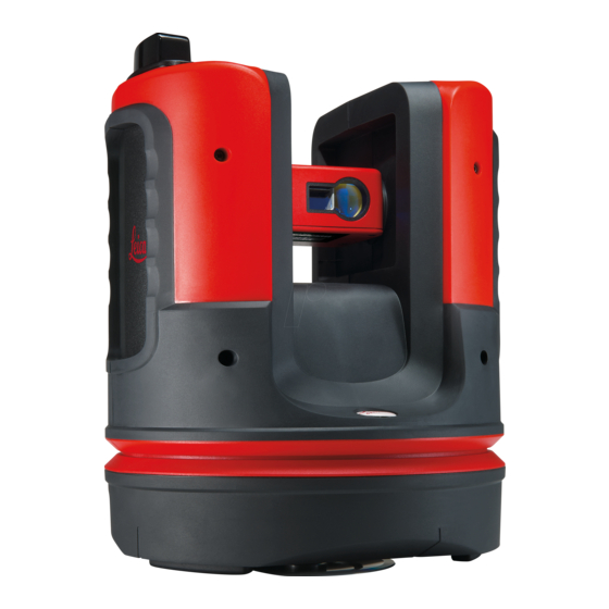
Container Contents (2/2) 010993_001 a) Ruler for offset points b) 3D Disto power supply Instrument Components 2.3.1 3D Disto Motor-driven Part a) LEDs for 3D Disto status b) ON/OFF button c) Grips to hold the instrument d) Infrared (IR) interface e) WLAN interface f) Laser distance meter with Point- finder... - Page 17 LEDs and Buttons Button/LEDs Description ON/OFF button Button to turn instrument ON or OFF. Instrument turns OFF after 15 minutes if not connected to the PC. 010732_001 LEDs for 3D Disto status • Green and orange LEDs light up continuously: 3D Disto is booting.
-
Page 18: Rm100 Remote Control
+10°C to +20°C/+50°F to +68°F if possible. • It is normal for the battery to become warm during charging. Using the chargers recommended by Leica Geosystems, it is not possible to charge the battery if the temperature is too high. - Page 19 3D Disto Power Only Leica Geosystems authorised service workshops are entitled to replace Supply the battery socket. • Internal: by battery socket, with non-removable Li-Ion batteries, 14.4 V, 63 Wh. • External: Power supply for 3D Disto connected by cable with country-specific plugs for worldwide use.
-
Page 20: 3D Disto Software
• 32 bit or 64 bit Insert the Leica USB memory stick only into a USB port “Type A”. For other port types, use an adapter. Ensure, that both the port and the adapter have “on- the-go” functionality (OTG). -
Page 21: User Interface
2.5.2 User Interface Home Screen All shown screens are examples. It is possible that local software versions vary from the standard version. a) Result window with result choice key b) Title bar with Home key c) Toolbar d) Sketch area/Pointfinder e) Main operation bar f) 3D Disto position g) Status bar... - Page 22 Operating Principles Selecting or Drawing Items for the Sketch View Ensure, that the navigation tools are deactivated. To select a point or line in the sketch, click with the mouse or tap with one finger. To draw a line, select a point with mouse, stylus or finger, slide to the desired point and release.
- Page 23 Toolbar of the Description Standard Applica- Enter and measure a reference height. tion (Measure) Start a line or surface scan. Disable line drawing. Go one point backward. Go one point forward. Confirm the current operation. Start area or volume mode. Undo or redo last command.
- Page 24 Icon Description Coordinates: X, Y and Z (Height) Tilt Horizontal/tilted area Horizontal/titled area perimeter Volume height Volume Circle size Circumference Diameter Scan area Scan perimeter Scan volume Distance between point and plane. Perpendicular distance of a point to the reference line. 3D Disto_052 Distance from the reference line base point to the foot of the perpen- dicular.
-
Page 25: Instrument Setup
Instrument Setup Setting Up 3D Disto Setup Step-by-Step The following description assumes setup on a tripod. You can also place the 3D Disto on flat surfaces such as floor or boards. Step Description It is always recommended to shield the instrument from direct sunlight and avoid uneven temperatures around the instrument. -
Page 26: Assistant
Step Description The following screen opens: 3D Disto connected via USB cable Step Description To work with cable connection to 3D Disto plug in USB cable and press 3D Disto connected via WLAN Step Description Depending on your Windows device it might be necessary to use the WLAN USB stick which is included in the delivery. -
Page 27: Tilt Sensor
Tilt Sensor Tilt Sensor A built-in tilt sensor ensures that measurements relate to true horizon or true plumb line, defined by gravity. The tilt is checked by a tilt sensor and the instrument levels itself if the tilt is < 3°. ... - Page 28 Settings Press Menu » Settings, the following options appear: • Snap Radius to define the area around a point/line. This setting offers a list of points that are very close to each other to simplify their selection. • Assistant to activate/deactivate the assistant. •...
-
Page 29: Data Management
Data Management 3.6.1 File Manager File Manager The File Manager handles the entire data administration measurement files, photos Secure Points and data transfer. To access the File Manager, press the Menu key and select File Manager. Description of keys: Icon Description Project folder Folder with photos... -
Page 30: Export And Import Of Data
• TXT file: all results in editable ASCII format. Same content like CSV file • JPG files of photos and Secure Points. Export data is transferred to the Export folder in the directory My Docu- ments\Leica Geosystems\3D Disto on your PC. Data Import Step... -
Page 31: Calculator
Calculator Using calculator • Tap on the result in the result window to start the calculator. • Another option is to press Menu » Calculator. 010862_001 Memory Function The memory function allows you to add or subtract results, e.g. areas or volumes. •... -
Page 32: Technical Terms And Abbreviations
Technical Terms and Abbreviations Horizontal Angle a) Horizontal angle: [°] or [gon] 010863_001 Vertical Angle Setting: Horizon = 0 a) Vertical angle: [°], [gon], [1:n] or [%] 010864_001 Setting: Horizon = 90°/100 gon a) Vertical angle: [°] or [gon] 010865_001 Distances a) Perpendicular distance 010867_001... - Page 33 Areas a) Tilted area, as measured b) Horizontal area, calculated by 3D Disto 010869_001 References +3.00 +2.10 0.00 0.00 -0.02 a) Reference height: 0.00 A level that all heights refer to. 010870_001 a) Reference axis/line: A line that all dimensions refer to. 010871_001 Tilt Sensor The tilt sensor guarantees correct results even if the 3D Disto is not set up horizon-...
- Page 34 Layout or Projection Design data in DXF and common table formats can be imported and used to lay out the corresponding points or grids. 010874_001 Laser Distance The laser distance meter (LDM) determines distances using a visible red laser beam. Meter Calibration Calibration is a workflow to check and adjust the accuracy of the instrument.
-
Page 35: Operation
Operation Measurements Description The 3D Disto is a combination of a precise laser distance meter (LDM) and angle encoders. Measurements are used to establish the relation between different targets, such as horizontal distances, tie distances, height differences to determine room dimensions, angles from wall to wall, areas, volumes, plumb points, or other features. -
Page 36: Measurement Workflow
Toolbar description Function Press to zoom in or out. Press to adjust the brightness of the camera. Press to display/hide all measured points. Press to measure hidden points. Select an offset tool in the pop-up: • Vertical offset: Measure one point on any vertical target. •... - Page 37 Step Description While targeting, ensure the laser beam is not split along corners or edges. 011133_001 Press to measure. Target the second point as described in the previous steps. A line is displayed from the first to the second measured point. Proceed as described for measuring further points or use to close/finish the polygon.
- Page 38 Step Description To change the view to a suitable perspective, use the navigation tools or click on the navigation cube. Press to choose between save, save as, clear screen, close measure- ments without saving. Areas & Volume The 3D Disto can also help determine areas and volumes. Both can be determined Calculations during or after measuring.
- Page 39 Step Description Pop-up appears to choose between the different options to define the height: • Enter height: Enter a desired value and press OK. • Measure height: Pointfinder opens, target and measure a point on floor with , followed by point on ceiling. You can measure the points anywhere on the floor or ceiling area.
-
Page 40: Software Applications
Software Applications Overview Description There are a variety of software application programs available addressing a wide spec- trum of construction tasks and facilitating daily work. • Measure: Provides practical features to measure room dimension, walls, windows, stairs and other details with reference height, manually or automatically. •... -
Page 41: Scan Tool For Automated Scans
6.2.2 Scan Tool for Automated Scans Description This tool executes automated horizontal, vertical and slope profile measurements and surface scans. Ideal for measuring rooms with non-square corners or curved walls, inaccessible points, slopes or areas. 010918_001 Line Scan, step-by- Step Description step Press... - Page 42 Step Description Vertical Line Scan: • Up (360°) • Point-to point • Down (360°) Slope Scan: Pointfinder opens. Target scan end and press Pop-up window prompts to define spacing of the measurement. Choose an interval and press OK or go to the rightmost position to enter indi- vidual intervals.
- Page 43 Step Description Press to save and close measurement file. Surface scan, step- Step Description by-step Press to start scan. Pop-up offers line scans and surface scans. Press for surface scan. Pop-up offers three scan options: horizontal, slope and vertical: Select your preference according to the surface you want to scan. ...
-
Page 44: Cad Tools
Step Description Press OK. Scan starts. The deviation of each scanned point to the reference plane is displayedin the result window. For geometric reasons, scan volume computation is an approximation. Toolbar changes. Press to start the camera. Press again to unlock. Press to change scan spacing, skip the rest of the scan, continue scan, or cancel scan. - Page 45 Circle Tool The circle tool’s purpose is mainly to draw a circle on points like sockets or holes. Step Description Target and measure a point and activate circle function by a long tap on the point in the sketch area. Select Circle.
- Page 46 Step Description Diagonal changes to a levelled rectangle. Line Intersection The Line Intersection tool finds the intersection point between two lines. Tool Step Description Intersection location is computed two-dimensionally in the X-Y plane. Inter- section point height is computed by extrapolation of the first line. Target and measure two points or select an existing line.
- Page 47 Line Extension Tool The Line Extension tool expands a line by a manually entered distance value. Step Description Line Extension end-point is computed as the 3-dimensional extrapolation of the selected line. Target and measure two points or select an existing line. Activate the CAD tools by a long tap on the line in the sketch are.
- Page 48 Point Shift Tool The Point Shift tool creates a new point by providing lateral movement value along an existing line, offset and offset angle. Step Description Point-shift location is computed two-dimensionally in the X-Y plane. New point height is computed by extrapolation of the selected line. Target and measure two points or select an existing line.
- Page 49 Step Description Press to continue. Assistant and pop-up ask for the offset. Enter a value and press OK. The shifted point is proposed: After was pressed, the new point is generated and the connecting line to the previous point is added. 1.800.561.8187 3D Disto, Software Applications information@itm.com...
- Page 50 Perpendicular Inter- The Perpendicular Intersection tool finds the perpendicular projection of a point on section Tool the selected line. Step Description Intersection location is computed two-dimensionally in the X-Y plane. Inter- section point height is computed by extrapolation of the first line. Target and measure two points or select an existing line.
-
Page 51: Projector
Projector Description This application projects points or geometrical grids onto a horizontal, vertical or sloped (= “free”) plane. Design data in DXF or table format can be imported or a grid’s geometry can be entered manually. 010958_001 6.3.1 Workflow Projector, Start Step Description Press Menu »... - Page 52 Grid mode Step Description Press to start Grid mode. Pop-up appears to choose between Define new, Use last or Measure. Select your preferred option: • Define new: use the subsequent tools to enter the grid’s geometry. • Use last: restore the last grid design that was entered. •...
- Page 53 Design Adjustment Step Description Use the key at any time to go back to Point Design. Aligner opens. The point design is now displayed in the working area and must be moved to the desired position. Use the following tools: ...
-
Page 54: Targeting And Layout With Rm100 Remote Control
Point projection Step Description Press to go back to the Aligner tool. In layout mode, the Toolbar changes and you can start to project the grid. Use the arrow keys to select a point and press You can also select points by tapping on a point on the screen or by using the remote control. -
Page 55: Location
Location Description The Location functions allow to change the position of the 3D Disto. Secure Points are placed by the user and make the positioning procedure easy. Secure Location Step Description step-by-step You have to measure two points first before Secure Points can be saved. Label and affix three to five self-adhesive target marks on walls, ceiling or floor around your working area. - Page 56 Step Description A lower tolerance increases the accuracy of your measurements and requires precise aiming and visibility of the Secure Points. If there are no Secure Points available but your measurement must fit to the geometry of a previous one, just start your measurement with the same Base Line points.
-
Page 57: Tool Kit
Location Check If the 3D Disto was unintentionally moved, for example got bumped, the geometry of step-by-step the measured points will no longer fit with that of the previously measured points. Start a Location Check to sustain the current accuracy/geometry. Step Description To initiate a Location Check press Menu »... -
Page 58: Comfort Targeting
Comfort plumbing Step Description step-by-step Start application in Menu » Applications » Tool Kit. The running application stays open in the background. Press on the Toolbar. Pointfinder opens. Target and measure the point to be plumbed. Press Pointfinder stays open. Roughly target expected plumb and press If plumb is found the laser flashes to indicate the exact position. -
Page 59: Comfort Level
6.5.3 Comfort Level Description Comfort levelling keeps the laser point at the same level when you turn the 3D Disto horizontally. Comfort levelling Step Description step-by-step Start application in Menu » Applications » Tool Kit. The running application stays open in the background. Press on the toolbar. -
Page 60: Height Tracking
Meter mark step- Step Description by-step Start application in Menu » Applications » Tool Kit. The running application stays open in the background. Press on the toolbar. Pop-up prompts to enter the height and measure that reference height. Pointfinder opens. Target reference point on the wall. -
Page 61: Parallel Line
6.5.6 Parallel Line Description Parallel line allows laying out lines parallel to a reference line on walls, floors, or tilted surfaces. Parallel Line step- Step Description by-step Start application in Menu » Applications » Tool Kit. The running application stays open in the background. Press on the toolbar. -
Page 62: Error Messages
Storage device does not work properly. Check file condition and content. File or Folder write-protected or damaged. 3D Disto error. Contact your distributor or Leica Geosystems representa- tive if the error repeats. The reflected laser signal is too low. The reflected laser signal is too high. -
Page 63: Check & Adjust
Check & Adjust Overview Description Leica Geosystems instruments are manufactured, assembled and adjusted to the best possible quality. Quick temperature changes, shock or stress can cause deviations and decrease the instrument accuracy. It is therefore recommended to check and adjust the instrument from time to time. -
Page 64: Crosshairs Offset
Crosshairs Offset Description The laser point and the crosshairs in the Pointfinder do not coincide. Before Calibration: After Calibration: 3D Disto_029 3D Disto_030 a) Crosshairs b) Laser point Adjustment step- Step Description by-step Calibration is started in Menu » Device » Calibration. Press Pointfinder opens Place a target mark at a distance >25 m. -
Page 65: Reset To Factory Settings
Adjustment step- Step Description by-step Set up the 3D Disto close to a wall with a steep target of good visibility that is at least 15 m above the instrument. 3D Disto_051 Calibration is started in Menu » Device » Calibration. Press Pointfinder opens Target as precisely as possible. -
Page 66: Instrument Protection (Theft Protection)
If the PUK code was entered correctly, the PIN code is set to default value “0” and the PIN protection is deactivated. Contact your Leica Geosystems representative if you need a replacement PUK. Activate PIN code... -
Page 67: Care And Transport
Shipping When transporting the product by rail, air or sea, always use the complete original Leica Geosystems packaging, transport container and cardboard box, or its equivalent, to protect against shock and vibration. Shipping, transport When transporting or shipping batteries, the person responsible for the product must... -
Page 68: Cleaning And Drying
10.3 Cleaning and Drying Housing and Optical • Blow dust off housing and optical components such as lenses or windows. Components • Never touch the glass with your fingers. • Use only a clean, soft, lint-free cloth for cleaning. If necessary, moisten the cloth with water or pure alcohol. -
Page 69: Technical Data
Technical Data 11.1 Technical Data Accuracy Tie at 10 m at 30 m at 50 m Distance (3D) Combination of angle and ca. 1 mm ca. 2 mm ca. 4 mm distance measurement Angle Measure- Working range: Horizontal 360°, Vertical 250° ment (Hz/V) Accuracy 5’’... -
Page 70: Conformity To National Regulations
• FCC Part 15, 22 and 24 (applicable in US). national regulations • Hereby, Leica Geosystems AG, declares that the 3D Disto and the RM100 are in compliance with the essential requirements and other relevant provisions of Direc- tive 1999/5/EC and other applicable European Directives. The declaration of conformity may be consulted at http://www.leica-geosystems.com/ce.
Need help?
Do you have a question about the Leica 3D Disto and is the answer not in the manual?
Questions and answers