Table of Contents
Advertisement
Quick Links
Advertisement
Table of Contents

Related Manuals for Leica GS09


Summary of Contents for Leica GS09
- Page 1 Leica GS09 User Manual Version 1.0 English...
- Page 2 The type and serial number of your product are indicated on the type plate. tion Enter the type and serial number in your manual and always refer to this information when you need to contact your agency or Leica Geosystems authorised service work- shop. Type: _______________ Serial No.:...
- Page 3 Windows is a registered trademark of Microsoft Corporation in the United States and other countries • CompactFlash and CF are trademarks of SanDisk Corporation • Bluetooth is a registered trademark of Bluetooth SIG, Inc. All other trademarks are the property of their respective owners. GS09, Introduction...
- Page 4 GS09, Introduction Validity of this This manual applies to the Leica GS09 GNSS. manual Available docu- Name Description/Format mentation GS09 User All instructions required in order to operate the Manual product to a basic level are contained in the User Manual.
- Page 5 Refer to the following resources for all Leica GS09 documentation/software: • the Leica GS09 CD-ROM • https://myworld.leica-geosystems.com CD-ROM contents The Leica GS09 CD-ROM contains software and documentation specific to Leica GS09: Type Description Software System software Language software Application programs...
- Page 6 View the service history of your products in Leica Geosystems Service Centers and detailed information on the services performed on your products. For your products that are currently in Leica Geosystems Service Centers view the current service status and the expected end date of service.
- Page 7 Service Description myTraining Enhance your product knowledge with the Leica Geosystems Campus - Information, Knowledge, Training. Study the latest online training material or download training material on your products. Keep up-to-date with the latest News on your products and register for Seminars or Courses in your country.
-
Page 8: Table Of Contents
GS09, Table of Contents Table of Contents In this manual Chapter Page Unpacking the Container Leica GS09 Container Contents SmartStation Container Contents Components of the CS09 Field Controller Components of the GHT56 Holder and GHT63 Clamp Using the CS09 Field Controller... - Page 9 Connecting to a Digital Cellular Phone Changing the Battery on the CS09 Field Controller Changing the CompactFlash card on the CS09 Field Controller 6.10 Changing the Battery on the GS09 Antenna 6.11 Essential Battery Operating Principles 6.12 Using Licence Keys 6.13 Checking and Adjusting the Circular Level of the Tribrach...
-
Page 10: Gs09, Table Of Contents
GS09, Table of Contents 6.14 Checking and Adjusting the Circular Bubble of the Pole 6.15 Guidelines for Correct Results with GNSS Surveys Connecting a Computer with ActiveSync Care and Transport Transport Storage Cleaning and Drying Safety Directions General Introduction Intended Use... - Page 11 10 Technical Data 10.1 CS09 Technical Data 10.2 GS09 Technical Data 10.2.1 Tracking Characteristics 10.2.2 Accuracy 10.2.3 Technical Data 10.3 GHT56 Technical Data 10.4 Conformity to National Regulations 10.4.1 CS09 10.4.2 GS09 10.4.3 GFU24 , Siemens MC75 10.4.4 GFU19 (US), GFU25 (CAN) CDMA MultiTech MTMMC-C...
-
Page 12: Unpacking The Container
GS09, Unpacking the Container Unpacking the Container Leica GS09 Container Contents Description The main components required for the Leica GS09 are combined in one transport container. Container for Leica a) GFU modem GS09 and delivered b) GRT146 carrier accessories part 1... - Page 13 2 of 2 Leic a GPS a) GEB211/GEB212 batteries Leic a GPS b) GEV205 Y-cable c) GS09 antenna d) GHT56 holder e) Spare stylus Antennas g) CD-ROM h) GFU modem GEV234 data cable GS09 antenna GS09_002 GS09, Unpacking the Container...
-
Page 14: Smartstation Container Contents
GS09, Unpacking the Container SmartStation Container Contents Container for SmartStation and delivered accesso- a) GAD33 arm 15 cm ries part 1 of 2 b) GS09 antenna c) Cables d) GHT63 pole clamp e) GAD31 adapter Antennas g) GAD104 SmartAntenna adapter... - Page 15 Manuals b) CompactFlash card c) GRZ4 / GRZ122 prism d) Spare stylus e) CD-ROM GEB211 / GEB212 batteries g) GHT56 holder h) 90° antenna adapter GEB221 battery CS09 field controller k) GHT39 holding plate GS09_004 GS09, Unpacking the Container...
-
Page 16: Components Of The Cs09 Field Controller
Hand strap top clips d) Stylus for touch screen e) Hand strap bottom clips Integrated USB and power port g) Battery and CompactFlash card compartment Bluetooth ports are included inside the CS09 field controller, for connectivity to GS09 antenna and cellular phones. GS09_006... -
Page 17: Components Of The Ght56 Holder And Ght63 Clamp
Pole clamp c) Clamp bolt GHT56 holder d) Tightening screw e) Mounting arm Clip-on-contacts for connecting CS09 field controller GS09_007 g) LED h) Mounting plate Port for connecting GFU modem Locking mechanism for battery k) Battery compartment GS09, Unpacking the Container... -
Page 18: Using The Cs09 Field Controller
GS09, Using the CS09 Field Controller Using the CS09 Field Controller The Keyboard Keyboard display PROG a) Function keys F1-F6 b) Alpha keys c) CAPS CAPS d) Hot keys F7-F12 SPACE e) SPACE, SHIFT SHIFT ENTER PgUp g) Arrow keys... - Page 19 Clears all entry at the beginning of user input. Clears the last character during user input. ENTER Selects the highlighted line and leads to the next logical menu / dialogue. Starts the edit mode for edit fields. Opens a choicelist. GS09, Using the CS09 Field Controller...
- Page 20 GS09, Using the CS09 Field Controller Function Leaves the current menu or dialogue without storing any changes. Turns field controller off when held for 2 s in the Main Menu screen. SHIFT Switches between the first and the second level of function keys.
- Page 21 Key combinations Function PROG plus USER Turns field controller off when held in the Main Menu screen. Pages up. SHIFT Pages down. SHIFT Displays the Windows CE task bar and start menu. SHIFT PROG ( GS09, Using the CS09 Field Controller...
-
Page 22: The Screen Display
GS09, Using the CS09 Field Controller The Screen Display Screen a) Time b) Caption c) Title d) Screen area e) Message line Icons g) ESC h) CAPS SHIFT icon Softkeys S_GS09_001 Elements Type Description Time The current local time is shown. - Page 23 SHIFT. Softkeys Commands can be executed using F1 - F6 keys. The commands assigned to the softkeys are screen dependent. Can be used directly with touch screen. GS09, Using the CS09 Field Controller...
-
Page 24: The Icons - Showing Field Controller Status
GS09, Using the CS09 Field Controller The Icons - Showing Field Controller Status Description Icons show information about the current status of the field controller. Position of the a b c d f icons on the screen a) Position status... - Page 25 Displays the number of theoretically visible satellites above the configured cut off satellites angle according to the current almanac. Touch screen: Tapping the icon leads to STATUS Satellites. Icon Description The number of visible satellites. GS09, Using the CS09 Field Controller...
- Page 26 GS09, Using the CS09 Field Controller Contributing satel- Displays the number of satellites that are contributing to the currently computed lites position solution. Touch screen: Tapping the icon leads to STATUS Satellites. Icon Description When a position status icon is displayed, the number of satellites currently used for the position computation are shown.
- Page 27 1 device is shown. Icon Description Radio transmitting Real-time mode: Rover An arrow pointing down indicates a rover configuration. The arrow flashes when real- time messages are received. Icon Description Radio receiving. Digital cellular phone receiving. GS09, Using the CS09 Field Controller...
- Page 28 GS09, Using the CS09 Field Controller Icon Description Field controller is online in the Internet. Position mode Displays the current position mode depending on the configuration defined. Symbols are added to the basic position mode icon when logging of auto points is configured.
- Page 29 Bluetooth The status of each Bluetooth port and any Bluetooth connection is displayed. Touch screen: Tapping the icon leads to STATUS Bluetooth. Icon Description Bluetooth is integrated. A Bluetooth connection is established and active. GS09, Using the CS09 Field Controller...
- Page 30 GS09, Using the CS09 Field Controller Data management The number of lines and areas currently open in the active job is displayed. Touch screen: Tapping the icon leads to MANAGE Data: Job Name Icon Description The number of lines and areas currently open.
- Page 31 SHIFT The status of the SHIFT key is displayed. Touch screen: Tapping the icon shows additional softkeys. Icon Description Additional softkeys are available in the currently visible screen. The SHIFT key has been pressed. GS09, Using the CS09 Field Controller...
-
Page 32: The Symbols - Showing Field Controller Settings
GS09, Using the CS09 Field Controller The Symbols - Showing Field Controller Settings Description Symbols show information about current field controller settings. Attributes Symbol Description Example The attribute symbol is displayed in the MANAGE Codes screen to indicate codes that have attributes attached. - Page 33 System program - DET C SYS Step 4: Check Resid- uals. Staked out Symbol Description Example The staked out symbol is used in the MANAGE Data: Job Name screen to indicate points which have been staked out. GS09, Using the CS09 Field Controller...
-
Page 34: Using The Gs09 Antenna
For most operations, pre-configured antenna settings in CS09 field controller can be used. These settings take the vertical phase centre variations into account. Leica GS09 accepts vertical height readings to the Mechanical Reference Plane, MRP. Vertical phase These are handled automatically in the standard antenna records. The antenna cali- centre variations brations to determine the phase centre variations were executed by Geo++®... - Page 35 Pole setup. For other than Leica poles, the dimensions must be determined. GS09, Using the GS09 Antenna...
-
Page 36: The Mechanical Reference Plane, Mrp
• varies for different antennas. MRP for GS09 The MRP for the GS09 antenna is shown in the diagram. antenna a) The mechanical reference plane is the underside of the threaded metal insert. -
Page 37: Measuring The Antenna Height For A Pillar Setup
MRP. quick overview a) Mechanical reference plane MRP b) Vertical phase centre offset for L1 c) Vertical phase centre offset for L2 d) Vertical Height Reading The Vertical offset = 0.00 GS09_0010 GS09, Using the GS09 Antenna... - Page 38 GS09, Using the GS09 Antenna Determining the Step Description antenna height Measure a height from the pillar benchmark to a surface on the carrier. with the GRT146 carrier step-by- step GS_036...
- Page 39 Use the appropriate measurement from the diagram above, to determine the height difference between the measured surface on the carrier and where the MRP of the GS09 antenna sits on the carrier. The vertical height reading = adding the values in step 1. and step 2.
-
Page 40: Measuring The Antenna Height For A Tripod Setup
GS09, Using the GS09 Antenna Measuring the Antenna Height for a Tripod Setup Measuring the Setup Type Antenna type The required measurement antenna height, a Tripod GS09 Tripod the vertical height reading from the height hook. quick overview a) Mechanical reference plane MRP... - Page 41 • The vertical offset of 0.36 m is automatically stored in the antenna setup record for a tripod setup and will automatically be taken into account. It does not need to be entered. GS09, Using the GS09 Antenna...
-
Page 42: Measuring The Antenna Height For A Pole Setup
GS09, Using the GS09 Antenna Measuring the Antenna Height for a Pole Setup Measuring the Setup Type Antenna type The required measurement antenna height, a Pole GS09 Pole the vertical height reading of the pole. quick overview a) Mechanical reference plane MRP... -
Page 43: The Led Indicators On The Gs09 Antenna
The LED Indicators on the GS09 Antenna LED indicators Description GS09 antenna has Light Emitting Diode indicators. They indicate the basic antenna status. Diagram of the LED indicators Tracking LED Bluetooth LED Power LED GS09_0013 GS09, Using the GS09 Antenna... - Page 44 GS09, Using the GS09 Antenna Description of the LED indicators IF the THEN No satellites are tracked. flashing green Less than four satellites are tracked, a position is not yet available. green Enough satellites are tracked to compute a position.
-
Page 45: Turning On / Turning Off
Rebooting from sleep mode is quicker than a cold start after turning off. sleep mode • CS09 field controller can only be put into sleep mode in the Main Menu screen. • Press SHIFT SLEEP (F3) to put CS09 field controller into sleep mode. GS09, Turning On / Turning Off... - Page 46 GS09, Turning On / Turning Off Switching between Leica SmartWorx software and the SmartWorx Windows CE desktop a) Icon to start Leica SmartWorx soft- ware b) Windows CE desktop c) Task bar d) Windows CE start button GS09_014 Accessing the Main Menu screen...
- Page 47 • select GS09 antenna in the task bar to maximise it. Accessing the Windows CE desktop THEN Leica SmartWorx software is to be mini- SHIFT MINIM (F5) in the Main Menu mised screen.
-
Page 48: Operating By Keyboard Or Touch Screen
GS09, Turning On / Turning Off Operating by Keyboard or Touch Screen Operating with the The user interface is operated either by the keyboard or by the touch screen, with keyboard and the supplied stylus. The workflow is the same for keyboard and touch screen entry, the touch screen only difference lies in the way information is selected and entered. -
Page 49: Understanding The Main Menu
To completely turn CS09 field controller off. SHIFT SLEEP (F3) To put CS09 field controller into sleep mode. SHIFT MINIM (F5) To minimise Leica SmartWorx soft- ware. SHIFT EXIT (F6) To close Leica SmartWorx software. GS09, Understanding the Main Menu... - Page 50 GS09, Understanding the Main Menu Description of the Main menu function Short description of functions Main Menu func- Survey • To start survey. tions Programs... • To select and start programs. Manage... • To manage jobs and their data, codelists and coordinate systems.
- Page 51 To view files in the CF card. • To manually type in or upload a licence key. • To perform arithmetic operations such as addition, subtraction, multiplication, division, statistical func- tions, trigonometric functions, conversions or roots. GS09, Understanding the Main Menu...
-
Page 52: Setting Up And Starting Up
GFU radio modem Transport container CS09 field controller k) GEB211 / GEB212 battery for CS09 field controller GS09_015 CompactFlash card m) GEB171 external battery n) GEV205 Y-cable The GRT146 carrier has a screw fitting. GS09 antenna fits directly onto this fitting. - Page 53 • Take the Y-cable. • Attach the connector with the 8 pin plug to GS09 antenna. • Attach the connector with the 5 pin plug to the external battery. • Attach the connector without pins to the radio housing.
- Page 54 GS09, Setting Up and Starting Up Step Description Starting Up with the Setup Reference Program 2.a Selecting the Job • Select a Job. • Press DATA (F5) to check all of the points in the selected job. • Press CONT (F1) to continue.
- Page 55 2.b Selecting the Antenna • Select the antenna.* For a pillar setup, select GS09 Pillar. For a tripod setup, select GS09 Tripod. • Press SRCH (F4) to start searching for the antenna, via Bluetooth. • Press CONT (F1) to continue.
- Page 56 GS09, Setting Up and Starting Up 2.d Selecting the Reference Point • Select the known point.*** • Enter the antenna height. For a pillar setup, this will be the vertical height reading to the MRP. For a tripod setup, this will be the vertical height reading from the height hook.
- Page 57 Refer to "3 Using the GS09 Antenna" for further information on antennas and antenna heights. ** Depending on the radio attached the screen content slightly differs. ***When setting the reference point for the setup, the selected point must be able to be viewed as WGS1984 coordinates.
-
Page 58: Setting Up For Raw Data Logging
GS09, Setting Up and Starting Up Setting Up for Raw Data Logging Diagram showing setup for raw data logging a) GS09 antenna b) Height hook c) CompactFlash card d) CS09 field controller e) GEV215 Y-cable GEB171 external battery g) Transport container... - Page 59 Set up the tripod, mount and level the tribrach onto the tripod. • Check that the tribrach is correctly centred over the marker. • Place and lock the carrier into the tribrach. • Screw GS09 antenna onto the carrier. GS09, Setting Up and Starting Up...
- Page 60 Hang the external battery onto a tripod leg. • Take the Y-cable. • Attach the connectors with the 8 pin plug to GS09 antenna and to CS09 field controller. • Attach the connector with the 5 pin plug to the external battery (internal batteries can also be used for powering GS09 antenna/CS09 field controller).
- Page 61 3.a Selecting the Job • Select the Job Default. • Select the WGS1984 coord system. • Press CONT (F1) to continue. GS09, Setting Up and Starting Up...
- Page 62 GS09, Setting Up and Starting Up 3.b Surveying the Point • Enter the point ID. • Enter the antenna height. For a tripod setup, this will be the vertical height reading from the height hook. • Press OCUPY (F1) to start measuring the point.*,**...
-
Page 63: Setting Up As A Real-Time Rover
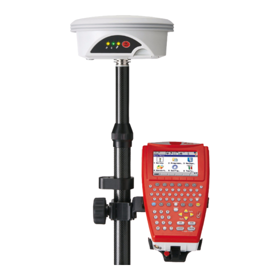
GHT63 pole clamp d) Snap-lock of the pole e) GLS30 telescopic pole Radio antenna g) GEB211 / GEB212 battery h) CompactFlash card CS09 field controller GEB211 / GEB212 battery k) GFU radio or GSM modem GS09_031 GS09, Setting Up and Starting Up... - Page 64 • Insert the battery into GS09 antenna. • Screw GS09 antenna onto the top of the telescopic pole. • Ensure that the compression lock is not clamped. • Fully extend the telescopic pole and ensure that the snap-lock clicks into its position.
- Page 65 Clip CS09 field controller onto the holder and lock into position. Refer to "Attaching CS09 field controller to the GHT56 holder step-by-step" for further information. • Turn on GS09 antenna and CS09 field controller. Starting Up with the Survey Program 2.a Selecting the Job •...
- Page 66 GS09, Setting Up and Starting Up 2.b Surveying the Point • Move to the point, enter the point ID. • Enter the antenna height. For Leica standard poles = 2.00 m. • Press OCUPY (F1) to start measuring the point.*,**,*** Press STOP (F1) when enough data is collected for the point.
- Page 67 Remove the thumb screw from the mounting plate. Remove the mounting arm from the mounting plate and re-position it. Re-fix the mounting arm to the mounting plate with the tightening screw. GS09, Setting Up and Starting Up...
- Page 68 GS09, Setting Up and Starting Up Attaching CS09 Step Description field controller to A locking mechanism is incorporated in the mounting plate of the holder. the GHT56 holder step-by-step Before CS09 field controller is placed onto the mounting plate ensure that the locking pin is put into the unlocked position.
- Page 69 Apply slight pressure in a downward direction and then lower the top part of CS09 field controller until the unit is clicked into the holder. The guides of the holder aid in this action. GS09_020 GS09, Setting Up and Starting Up...
- Page 70 GS09, Setting Up and Starting Up Step Description After CS09 field controller is placed onto the mounting plate ensure that the locking pin is put into the locked position. To lock the locking pin, push up the red button from below.
- Page 71 Step Description While in this position, raise the top of CS09 field controller from the holder. GS09_021 GS09, Setting Up and Starting Up...
-
Page 72: Led Indicators On Ght56
GS09, Setting Up and Starting Up LED Indicators on GHT56 LED indicator Description GHT56 has one Light Emitting Diode indicator. It indicates the basic power status. Diagram a) Power LED GS09_022... - Page 73 The remaining time for which enough power is available depends on the type of survey, the temperature and the age of the battery. power is very low. The battery should be changed. GS09, Setting Up and Starting Up...
-
Page 74: Working With The Clip-On-Housings For Devices On Ght56
GS09, Setting Up and Starting Up Working with the Clip-On-Housings for Devices on GHT56 Devices fitting into Digital cellular phones for GPS RTK fitting into a clip-on-housing a clip-on-housing Digital cellular phone Clip-on-housing Siemens MC75 GFU24 CDMA MultiTech MTMMC-C (US) - Page 75 Ensure that the circular screw is in the unlocked position. Turn it anticlockwise, as shown by the lock and arrow symbols on the screw. Turn GHT56 over to gain access to the space for the clip-on-housing. GS09, Setting Up and Starting Up...
- Page 76 GS09, Setting Up and Starting Up Step Description Place the clip-on-housing into position such that • the guide rails on the GHT56 are aligned with the guide rails on the clip-on-housing. • the LEMO port on the GHT56 is aligned with the connector on the clip- on-housing.
- Page 77 Locate the SIM card screw, that covers the SIM card slot, on the bottom of the clip-on-housing. Insert the coin into the groove of the SIM card screw. Turn the coin anticlockwise to loosen the SIM card screw. Remove the SIM card screw from the housing. GS09, Setting Up and Starting Up...
- Page 78 GS09, Setting Up and Starting Up Step Description Using the pen, press the small button of the SIM card slot to eject the SIM card holder. Take the SIM card holder out off the housing. Put the SIM card into the SIM card holder, the chip facing up.
- Page 79 Put the SIM card holder back into the SIM card slot, the even side not facing the contacts inside the slot. Place the SIM card screw back on the housing. Turn the coin clockwise to tighten the SIM card screw. GS09, Setting Up and Starting Up...
- Page 80 GS09, Setting Up and Starting Up LED indicators Description Each clip-on-housing for a radio, digital cellular phones or Bluetooth communication has Light Emitting Diode indicators on the bottom side. They indicate the basic device status. Diagram a) Configuration LED b) Data Transfer LED...
- Page 81 Signal GFU19 (US), device is on, not registered on the strength GFU25 (CAN) network. with CDMA flashing red device is on, registered on the MultiTech network. MTMMC-C download mode or device is off. GS09, Setting Up and Starting Up...
- Page 82 GS09, Setting Up and Starting Up IF the THEN GFU24 with call is in progress. Siemens MC75 red: long flash, no SIM card inserted, no PIN entered long break or network search, user authentica- tion or network login in progress.
-
Page 83: Connecting To The Gs09 Antenna With Bluetooth
Bluetooth step-by- step Select Main Menu: Select Comm: Bluetooth. Press SRCH (F4) to search for Bluetooth devices. The GS09 antenna must be turned on. The CONFIGURE Search Bluetooth Device screen appears. All available Bluetooth devices are displayed. Highlight and select the antenna to be used. -
Page 84: Connecting To A Digital Cellular Phone
GS09, Setting Up and Starting Up Connecting to a Digital Cellular Phone Connecting step- Step Description by-step Select Main Menu: Highlight Real-Time. EDIT (F3) CONFIGURE Real-Time Mode <R-Time Mode: Rover> Select a free Bluetooth port. DEVCE (F5) CONFIGURE Devices Highlight a Bluetooth capable digital cellular phone. - Page 85 If the digital cellular phone selected is connected for the first time, the Windows CE dialog for pairing comes up. Type in 0000 as iden- tification number for Leica’s Bluetooth and click OK. Some digital cellular phones also ask for the identification number for Leica’s Bluetooth.
-
Page 86: Changing The Battery On The Cs09 Field Controller
GS09, Setting Up and Starting Up Changing the Battery on the CS09 Field Controller Changing the battery on CS09 field controller step-by-step GS09_023 Step Description Turn CS09 field controller over to gain access to the battery compartment. Push the slide fastener in the direction of the arrow with the open-lock symbol. - Page 87 Place the battery into the battery compartment, ensuring that the engraved arrow symbol is pointing toward the battery contacts. Close the battery compartment by pushing the slide fastener in the direc- tion of the arrow with the close-lock symbol. GS09, Setting Up and Starting Up...
-
Page 88: Changing The Compactflash Card On The Cs09 Field Controller
GS09, Setting Up and Starting Up Changing the CompactFlash card on the CS09 Field Con- troller Changing the CompactFlash card on CS09 field controller step-by- step GS09_024 Step Description The CompactFlash card is inserted into a slot inside the battery compart-... - Page 89 To remove the card, open the cover of the battery compartment. Pull the battery from the battery compartment. Press the eject button on the right side of the card slot twice. Pull out the CompactFlash card and close the compartment cover. GS09, Setting Up and Starting Up...
-
Page 90: Changing The Battery On The Gs09 Antenna
GS09_025 Step Description Turn GS09 antenna over to gain access to the battery compartment. Open the battery compartment by pushing the slide fastener in the direc- tion of the arrow with the open-lock symbol. Pull out the battery housing. The battery is attached to the housing. - Page 91 Place the battery onto the battery housing, ensuring that the contacts are facing outward. Click the battery into position. Close the battery compartment by pushing the slide fastener in the direc- tion of the arrow with the close-lock symbol. GS09, Setting Up and Starting Up...
-
Page 92: Essential Battery Operating Principles
+10°C to +20°C/+50°F to +68°F if possible. • It is normal for the battery to become warm during charging. Using the chargers recommended by Leica Geosystems, it is not possible to charge the battery if the temperature is too high. Operation/Discharging •... -
Page 93: Using Licence Keys
Protected A licence key is required for the following protected programs: programs Protected programs • DTM Stakeout • Reference Line • RoadRunner • Volume Calculations GS09, Setting Up and Starting Up... - Page 94 GS09, Setting Up and Starting Up Protected instru- A licence key is required for the following protected instrument options: ment options Protected instrument options • 5 Hz update rate • 5 km RTK range • Unlimited RTK range • Extended OWI messages •...
- Page 95 Upload Key File. The licence key file is uploaded from the CompactFlash card. The licence key file must be stored in the \SYSTEM directory in the CompactFlash card. • Manual Entry of Key. Allows the licence key to be typed in manually. GS09, Setting Up and Starting Up...
- Page 96 GS09, Setting Up and Starting Up Field Description of Field • Available for <Method: Manual Entry of Key>. The licence key required to activate a program. Entry is not case sensitive. The next step IF a licence THEN key is to be uploaded select the method used to input the licence key and press CONT (F1).
-
Page 97: Checking And Adjusting The Circular Level Of The Tribrach
Description • The adjustable circular level on the tribrach is used to level the GS09 antenna over the observation point. An incorrectly adjusted circular level means that the GS09 antenna is not properly positioned over the point, which means that another point on the ground is observed. - Page 98 GS09, Setting Up and Starting Up Checking and Step Description adjusting the Set up the tripod. circular level step- by-step Screw the tribrach onto the tripod. Fix the carrier/instrument onto the tribrach. Level the tribrach using the precision bubble on the carrier or the precision bubble on the instrument.
- Page 99 Centre the circular level using the adjustment pin in conjunc- tion with the adjustment screws on the underside of the casing of the circular level. GS09_027 Fix the carrier/instrument onto the tribrach. Repeat steps 4. to 5. GS09, Setting Up and Starting Up...
-
Page 100: Checking And Adjusting The Circular Bubble Of The Pole
It is important that the adjustable circular bubble of the pole is kept in adjustment. adjusting the Whenever the Leica GS09 equipment is sent for servicing to a Leica Geosystems circular bubble authorised service workshop, it is recommended that the pole is also sent for serv-... -
Page 101: Guidelines For Correct Results With Gnss Surveys
For static surveys, the antenna must be kept perfectly steady throughout the whole static surveys occupation of a point. Place the antenna on a tripod or pillar. Centred and Centre and level the antenna precisely over the marker. levelled antenna GS09, Setting Up and Starting Up... -
Page 102: Connecting A Computer With Activesync
Before data can be transferred, the ActiveSync software must first be installed on Sync the office computer. The ActiveSync software is freeware and is supplied on the Leica GS09 CD ROM. Translated versions can be downloaded from the Microsoft website. - Page 103 Select the No option (Windows Updates), click Next to continue. • Select Install from a list or specific location, click Next to continue. • Insert the Leica GS09 CD ROM, which contains the necessary USB driver. • Select Search removable media, click Next to continue.
- Page 104 GS09, Connecting a Computer with ActiveSync Step Description • Start Microsoft ActiveSync on the office computer. • From the File menu, select Connection Settings. Ensure that the Allow USB connection with this desktop computer is checked. Click OK to close the dialogue.
- Page 105 USB cable step-by-step • Turn on CS09 field controller by pressing and holding PROG (ON) for 2 s. • Connect the USB cable to CS09 field controller but not to the office computer. GS09, Connecting a Computer with ActiveSync...
- Page 106 • CS09 field controller is connected to ActiveSync as a guest. Setting up LEICA Geo Office • Start LEICA Geo Office on the office computer. • Open Data Exchange Manager from the Tools menu. • Click Refresh (F5) on the ActiveSync folder.
- Page 107 Click the - -> arrow to move the service to the Trusted box. • Highlight the service required in the Trusted box. • Right mouse click to access the context menu. • Tick Active. GS09, Connecting a Computer with ActiveSync...
- Page 108 ActiveSync establishes the link between the office computer and CS09 field controller. Setting up LEICA Geo Office • Start LEICA Geo Office on the office computer. • Open Data Exchange Manager from the Tools menu. • Click Refresh (F5) on the ActiveSync folder.
-
Page 109: Care And Transport
Always carry the product in its transport container and secure it. Shipping When transporting the product by rail, air or sea, always use the complete original Leica Geosystems packaging, transport container and cardboard box, or its equiva- lent, to protect against shock and vibration. Shipping, transport... -
Page 110: Storage
GS09, Care and Transport Storage Product Respect the temperature limits when storing the equipment, particularly in summer if the equipment is inside a vehicle. Refer to "10 Technical Data" for information about temperature limits. Li-Ion batteries • Refer to "10 Technical Data" for information about storage temperature range. -
Page 111: Cleaning And Drying
Always close the transport container when using in the field. Cables and plugs Keep plugs clean and dry. Blow away any dirt lodged in the plugs of the connecting cables. Connectors with Wet connectors must be dry before attaching the dust cap. dust caps GS09, Care and Transport... -
Page 112: Safety Directions
GS09, Safety Directions Safety Directions General Introduction Description The following directions enable the person responsible for the product, and the person who actually uses the equipment, to anticipate and avoid operational hazards. The person responsible for the product must ensure that all users understand these... -
Page 113: Intended Use
Carrying out measurement tasks using various GNSS measuring techniques. • Recording GNSS and point related data. • Data communication with external appliances. • Measuring raw data and computing coordinates using carrier phase and code signal from GNSS satellites. GS09, Safety Directions... - Page 114 GS09, Safety Directions Adverse use • Use of the product without instruction. • Use outside of the intended limits. • Disabling safety systems. • Removal of hazard notices. • Opening the product using tools, for example screwdriver, unless this is permitted for certain functions.
-
Page 115: Limits Of Use
Danger Local safety authorities and safety experts must be contacted before working in hazardous areas, or close to electrical installations or similar situations by the person in charge of the product. GS09, Safety Directions... -
Page 116: Responsibilities
Manufacturers of The manufacturers of non Leica Geosystems accessories for the product are respon- non Leica Geosys- sible for developing, implementing and communicating safety concepts for their... - Page 117 The person responsible for the product must ensure that it is used in accordance with the instructions. This person is also accountable for the training and the deployment of personnel who use the product and for the safety of the equipment in use. GS09, Safety Directions...
-
Page 118: Hazards Of Use
GS09, Safety Directions Hazards of Use Warning The absence of instruction, or the inadequate imparting of instruction, can lead to incorrect or adverse use, and can cause accidents with far-reaching human, material, financial and environmental consequences. Precautions: All users must follow the safety directions given by the manufacturer and the direc- tions of the person responsible for the product. - Page 119 Inadequate securing of the working site can lead to dangerous situations, for example in traffic, on building sites, and at industrial installations. Precautions: Always ensure that the working site is adequately secured. Adhere to the regulations governing safety and accident prevention and road traffic. GS09, Safety Directions...
- Page 120 GS09, Safety Directions Warning If computers intended for use indoors are used in the field there is a danger of elec- tric shock. Precautions: Adhere to the instructions given by the computer manufacturer regarding field use with Leica Geosystems products.
- Page 121 If there is a risk of a thunderstorm, or if the equipment is to remain unused and unattended for a long period, protect your product additionally by unplugging all systems components and disconnecting all connecting cables and supply cables, for example, instrument - antenna. GS09, Safety Directions...
- Page 122 GS09, Safety Directions Lightning conduc- Suggestion for design of a lightning conductor for a GNSS system: tors 1) On non-metallic structures Protection by air terminals is recommended. An air terminal is a pointed solid or tubular rod of conducting material with proper mounting and connection to a conductor.
- Page 123 Metallic mast e) Connection to earth GS_040 Warning Using a battery charger not recommended by Leica Geosystems can destroy the batteries. This can cause fire or explosions. Precautions: Only use chargers recommended by Leica Geosystems to charge the batteries.
- Page 124 GS09, Safety Directions Precautions: Before shipping the product or disposing of it, discharge the batteries by running the product until they are flat. When transporting or shipping batteries, the person in charge of the product must ensure that the applicable national and international rules and regulations are observed.
- Page 125 By disposing of the product irresponsibly you may enable unauthorised persons to use it in contravention of the regulations, exposing themselves and third parties to the risk of severe injury and rendering the environment liable to contamination. GS09, Safety Directions...
- Page 126 Always prevent access to the product by unauthorised personnel. Product-specific treatment and waste management information can be downloaded from the Leica Geosystems home page at http://www.leica- geosystems.com/treatment or received from your Leica Geosystems dealer. Warning Only Leica Geosystems authorised service workshops are entitled to repair these products.
-
Page 127: Electromagnetic Compatibility Emc
Warning Electromagnetic radiation can cause disturbances in other equipment. Although the product meets the strict regulations and standards which are in force in this respect, Leica Geosystems cannot completely exclude the possibility that other equipment may be disturbed. Caution There is a risk that disturbances may be caused in other equipment if the product is used with accessories from other manufacturers, for example field computers, personal computers, two-way radios, non-standard cables or external batteries. - Page 128 Although the product meets the strict regulations and standards which are in force in this respect, Leica Geosystems cannot completely exclude the possibility that the product may be disturbed by intense electromagnetic radiation, for example, near radio transmitters, two-way radios or diesel generators.
- Page 129 Precautions: Although the product meets the strict regulations and standards which are in force in this respect, Leica Geosystems cannot completely exclude the possibility that other equipment can be disturbed or that humans or animals can be affected. • Do not operate the product with radio or digital cellular phone devices in the vicinity of filling stations or chemical installations, or in other areas where an explosion hazard exists.
-
Page 130: Fcc Statement, Applicable In U
GS09, Safety Directions FCC Statement, Applicable in U.S. The greyed paragraph below is only applicable for products without radio. Warning This equipment has been tested and found to comply with the limits for a Class B digital device, pursuant to part 15 of the FCC rules. - Page 131 Warning Changes or modifications not expressly approved by Leica Geosystems for compli- ance could void the user's authority to operate the equipment. Labelling CS09 Type: CS09 ... This device complies with part .
- Page 132 GS09, Safety Directions Labelling GHT56 Type: GHT 56 ..This device complies with ....part 15 of the FCC Rules. Operation is subject to the .
- Page 133 This device complies with part 15 of the FCC Rules. Operation is subject to the following two conditions: (1) This device may not cause harmful interference, and (2) this device must accept any interference received, including interference that may cause undesired operation. GEV_001 GS09, Safety Directions...
-
Page 134: Technical Data
GS09, Technical Data Technical Data 10.1 CS09 Technical Data Design Glass reinforced polymer housing with integrated battery. Display: 1/4 VGA (320 x 240 pixels), color, graphics capable LCD, illumi- Control unit nation, touch screen Keyboard: 62 keys including 12 function keys, illumination Angle Display: 360°’", 360°... - Page 135 Power Type Consumption [W] External supply voltage CS09 Nominal voltage 12 V DC ( Bluetooth to GS09, Voltage range 10.5 V-28 V radio receiving data Recording Data can only be recorded on the CompactFlash card. Type Capacity [MB] Data capacity CompactFlash •...
- Page 136 GS09, Technical Data Environmental Temperature specifications Type Operating temperature [°C] Storage temperature [°C] CS09 -30 to +65 -40 to +80 Bluetooth: -25 to +65 Color display: -30 to +50 Internal battery -20 to +50 -40 to +70 Protection against water, dust and sand...
- Page 137 Interfaces Type Bluetooth CS09 LEMO port Class 2 Connector • 8 pin LEMO-1 • 7 pin clip-on-contacts GS09, Technical Data...
-
Page 138: Gs09 Technical Data
GS09, Technical Data 10.2 GS09 Technical Data 10.2.1 Tracking Characteristics Antenna tech- SmartTrack+ nology Satellite reception Dual frequency Antenna channels 14 channels continuous tracking on L1 and L2 (GPS); twelve channels continuous tracking on L1 and L2 (GLONASS). Supported codes... - Page 139 Reconstructed carrier phase via C/A code Reconstructed carrier phase via P2 code Code measure- ments Condition GS09 L1, AS off Carrier phase smoothed code measurements: C/A code L1, AS on L2, AS off Carrier phase smoothed code measurements: P2 code GS09, Technical Data...
- Page 140 GS09, Technical Data Condition GS09 L2, AS on Carrier phase smoothed code measurements: Patented P code-aided code GLONASS Condition GS09 Carrier phase smoothed code measurements: C/A code Carrier phase smoothed code measurements: P2 code Carrier phase and code measurements on L1 and L2 are fully independent with AS on or off.
-
Page 141: Accuracy
10 mm + 1 ppm 20 mm + 1 ppm Differential phase Static Kinematic in real-time Horizontal Vertical Horizontal Vertical 5 mm + 0.5 ppm 10 mm + 0.5 ppm 10 mm + 1 ppm 20 mm + 1 ppm GS09, Technical Data... -
Page 142: Technical Data
GS09, Technical Data 10.2.3 Technical Data Dimensions Height: 0.089 m Diameter: 0.186 m Connector • 8 pin LEMO-1 • 5 pin SmartStation clip-on contacts Mounting 5/8" Whitworth Weight 1.1 kg including internal battery Power consumption: 1.8 W typically Power External supply voltage: Nominal 12 V DC ( ), voltage range 10.5 V-28 V... - Page 143 Typically 27 dBi Noise Figure Typically < 2 dBi Environmental Temperature specifications Operating temperature [°C] Storage temperature [°C] -40 to +65 -40 to +80 Bluetooth: -30 to +65 Protection against water, dust and sand Protection IP67 (IEC 60529) Dusttight GS09, Technical Data...
- Page 144 GS09, Technical Data Protection Protected against water jets Waterproof to 1 m temporary immersion Humidity Protection Up to 100 % The effects of condensation are to be effectively counteracted by periodically drying out the antenna.
-
Page 145: Ght56 Technical Data
Typical operating time: The given operating times are valid for • one fully charged GEB221 battery. • 25°C. Operating times will be shorter when working in cold weather. • good data link. GFU14, receive only mode: 16 h GS09, Technical Data... - Page 146 GS09, Technical Data Environmental Temperature specifications Operating temperature [°C] Storage temperature [°C] -20 to +65 -40 to +80 Protection against water, dust and sand Protection IP67 (IEC 60529) Dusttight Protected against water jets Waterproof to 1 m temporary immersion Humidity...
-
Page 147: Conformity To National Regulations
Conformity to • FCC Part 15, 22 and 24 (applicable in US) • Hereby, Leica Geosystems AG, declares that the product CS09 is in compliance national regula- with the essential requirements and other relevant provisions of Directive tions 1999/5/EC. The declaration of conformity can be consulted at http://www.leica- geosystems.com/ce. - Page 148 GS09, Technical Data Antenna Type Antenna Gain Connector Frequency band [dBi] [MHz] CS09, Bluetooth Integrated antenna...
-
Page 149: Gs09
• FCC Part 15, 22 and 24 (applicable in US) Conformity to • Hereby, Leica Geosystems AG, declares that the product GS09 is in compliance national regula- with the essential requirements and other relevant provisions of Directive tions 1999/5/EC. The declaration of conformity can be consulted at http://www.leica- geosystems.com/ce. - Page 150 GS09, Technical Data Output power Type Output power [mW] GNSS Receive only Bluetooth GNSS Internal GNSS antenna element (receive only) Antenna Bluetooth Type: Internal Microstrip antenna Gain: 1.5 dBi...
-
Page 151: Gfu24, Siemens Mc75
• FCC Part 15, 22 and 24 (applicable in US) Conformity to • Hereby, Leica Geosystems AG, declares that the GFU24 is in compliance with the national regula- essential requirements and other relevant provisions of Directive 1999/5/EC. The tions declaration of conformity may be consulted at http://www.leica-geosys- tems.com/ce. - Page 152 GS09, Technical Data Antenna Type GAT 3 GAT 5 Frequency band [MHz] 890 - 960 / 824 - 894 / 1710 - 1880 / 1850 - 1990 1920 - 2170 Detachable λ/2 antenna Detachable λ/2 antenna Type Connector Specific Absorption...
-
Page 153: Gfu19 (Us), Gfu25 (Can) Cdma Multitech Mtmmc-C
FCC part 15, 22 and 24 has to be approved prior to use and operation. Frequency band Dual-Band CDMA850 MHz/CDMA1900 MHz CDMA850: Output power CDMA1900: 0.4 W Antenna Type GAT 5 Frequency band [MHz] 824 - 894 / 1850-1990 Detachable λ/2 antenna Type Connector GS09, Technical Data... - Page 154 GS09, Technical Data Specific Absorption The product meets the limits for the maximum permissible exposure of the guide- Rate (SAR) lines and standards which are force in this respect. The product must be used with the recommended antenna. A separation distance of at least 20 centimetres should be kept between the antenna and the body of the user or nearby person within the intended application.
-
Page 155: International Limited Warranty, Software Licence Agreement
Leica Geosystems. Such software is protected by copy- right and other laws and its use is defined and regulated by the Leica Geosystems Software Licence Agreement, which covers aspects such as, but not limited to, Scope of the Licence, Warranty, Intellectual Property Rights, Limitation of Liability, Exclusion of other Assurances, Governing Law and Place of Jurisdiction. - Page 156 You must not install or use the software unless you have read and accepted the terms and conditions of the Leica Geosystems Software Licence Agreement. Installa- tion or use of the software or any part thereof, is deemed to be an acceptance of all the terms and conditions of such Licence Agreement.
-
Page 157: Appendix A Directory Structure Of The Memory Device
|—— DATA • ASCII, DXF, LandXML, GSI8, GSI16 files for import/export to/from job (*.*) • Logfiles created from application programs |—— GPS • Almanac file (Almanac.sys) |—— CSCS • CSCS field files (*.csc) GS09, Directory Structure of the Memory Device... - Page 158 GS09, Directory Structure of the Memory Device |—— GEOID • Geoid field files (*.gem) |—— RINGBUF • Ring buffer files |—— DBX • Job files, various files • DTM jobs, various files • Coordinate system file (Trfset.dat) |—— GPS •...
-
Page 159: Index
Index Bluetooth ............24 Icon ..............29 ActiveSync ............102 LED on GS09 ..........43 Antenna Calibration ............. 34 Antenna channels ..........138 Calibration, antennas ..........34 Antenna file, directory ........158 Capacity, memory ..........135 Antenna technology .......... 138 Carrier tracking ..........139 Antennas Clip-on-housing CS09 ............ - Page 160 Coordinate system file, directory ...... 158 CS09 Environmental specifications Graphical overview of underside ....16 GHT56 ............146 Minimise Leica SmartWorx software ....49 GS09 ............143 Operating principles ........48 Operating temperature ........ 136 FCC Statement ..........130 Storage temperature ........136 Filter Turn off ...........
- Page 161 Housing for devices ..........74 Job file, directory ..........158 Icons ..............24 Key Combinations ..........21 Indicators, LED Keyboard Clip-on-housing ..........80 Graphical overview .........18 GHT56 ............72 Operating principles ........48 GS09 ............. 43 Insert SIM card ............77 GS09, Index...
- Page 162 Alpha keys ............. 20 Arrow keys ............ 20 Clip-on-housing, description ......81 CAPS key ............19 GHT56, description .........73 CE key ............19 GS09, description ........43, 44 Combinations ..........21 Housing, description ........80 Description of ..........19 Leica SmartWorx software ENTER key ............19 Accessing ............46...
- Page 163 GS15 ............150 Manage............... 50 Mechanical Reference Plane ........ 36 Microsoft ActiveSync ......... 102 Phase center variations, vertical ......34 Minimise Leica SmartWorx software on CS09 ..49 Position mode .............24 Mount, GS09 ............. 142 Icon ..............28 MRP ..............36 Position status, icon ..........24...
- Page 164 Sleep mode on CS09 ...........49 Software Licence Agreement ......155 Specifications, environmental Safety Directions ..........112 GHT56 ............146 Satellite reception ..........138 GS09 ............143 Satellite tracking data, GS09 ......143 Staked out, symbol ..........33 Satellites Status Contributing ........... 24 Position ............24 Icon ............25, 26 Status, device .............80...
- Page 165 Switching, Leica SmartWorx software and Windows CE ............... 46 User Manual Symbols .............. 32 Validity of ............4 System file, directory ........158 Vertical offset, antenna .........34, 40 Technical Data Volume Calculations ..........93 Dimensions ..........134 Display and keyboard ........134 Weight Environmental specifications ......
- Page 166 International Standards of Quality Management and Quality Systems (ISO standard 9001) and Environmental Management Systems (ISO standard 14001). Ask your local Leica Geosystems dealer for more information about our TQM program. Leica Geosystems AG Heinrich-Wild-Strasse...
Need help?
Do you have a question about the GS09 and is the answer not in the manual?
Questions and answers