Datamax a-class mark ii Operator's Manual
Hide thumbs
Also See for a-class mark ii:
- Programmer's manual (330 pages) ,
- Quick start manual (6 pages)
Table of Contents
Advertisement
Quick Links
Advertisement
Table of Contents

Related Manuals for Datamax a-class mark ii


Summary of Contents for Datamax a-class mark ii
- Page 1 Operator’s Manual...
- Page 3 Information in this document is subject to change without notice and does not represent a commitment on the part of Datamax-O’Neil Corporation. No part of this manual may be reproduced or transmitted in any form or by any means, for any purpose other than the purchaser's personal use, without the expressed written permission of Datamax-O’Neil Corporation.
- Page 4 Agency Compliance and Approvals: UL60950-1 First Edition, Information Technology Equipment CSA C22.2 No.60950-1-03, First Edition Listed IEC 60950-1, 2001, First Edition The manufacturer declares under sole responsibility that this product conforms to the following standards or other normative documents: EMC: EN 55022 (2006,A1:2007) Class B EN 50024 (1998,A1:2001,A2:2003) Safety: This product complies with the requirements of IEC 60950-1, 2001, First Edition...
-
Page 6: Important Safety Instructions
Important Safety Instructions: Throughout the literature accompanying this unit, the exclamation point within an equilateral triangle is intended to alert the user to the presence of important operating and maintenance instructions. This unit has been carefully designed to provide years of safe, reliable performance. However, as with all electrical equipment, there are some basic precautions that you should follow to avoid personal injury or damage to the printer: Before using the print engine, carefully read all the installation and operating... -
Page 7: Table Of Contents
Contents Overview ..................1 1.1 About the Printer ....................1 1.1.1 Standard Features..............2 1.1.2 Optional Features..............3 2 Getting Started ................5 2.1 Unpacking ......................5 2.1.1 Contents..................6 2.1.2 Additional Requirements ............6 2.2 Mounting Requirements ..................7 2.3 Host Connections ..................... 11 2.3.1 Parallel Port Connections............ - Page 8 4 Using the Control Panel .............. 28 4.1 Layout ......................28 4.1.1 The Display ................28 4.1.2 Keypad Functions..............30 4.2 The System Menu .................... 31 4.2.1 Media Settings................ 32 4.2.2 Print Control................35 4.2.3 Printer Options ............... 37 4.2.4 System Settings ..............45 4.2.5 Communications ..............
- Page 9 5.6 Maintenance Schedule..................90 5.6.1 Cleaning the Printhead............. 91 5.6.2 Cleaning the Rollers ..............93 5.6.3 Cleaning the Peel Assembly ............94 5.6.4 Cleaning the Media Sensor, Media Path, and Peel Bar ....96 5.6.5 Cleaning Exterior Surfaces ............97 5.7 Reset Methods ....................
- Page 10 Appendix A ................... 125 Module Assignments ....................125 File Handling Messages ..................125 Cut Behind Setup ....................127 Appendix B ................... 129 Print Resolutions and Widths ................. 129 Speed Ranges ....................... 129 Column & Row Emulation Ranges ................. 130 Custom Adjustments: ..................... 130 Column, Present, &...
-
Page 11: Overview
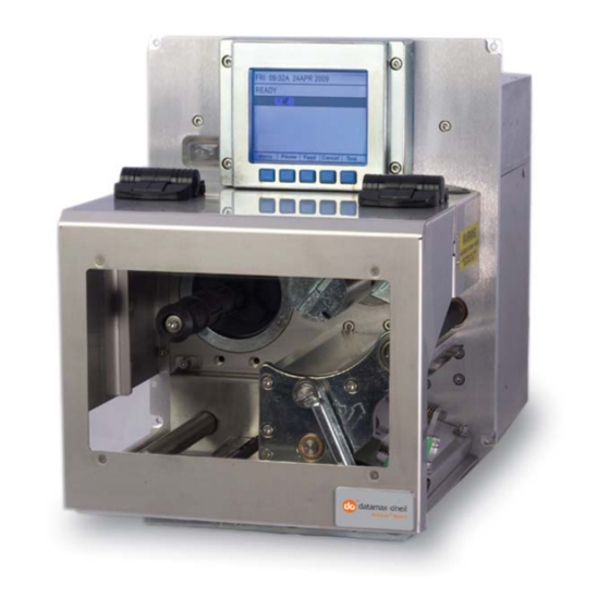
Overview 1.1 About the Printer Congratulations on your purchase of an A-Class Mark II printer. This print engine (hereafter referred to as “the printer” and, when necessary, by model) is designed for professional integration into an industrial applicator system. This manual provides all the information necessary for installation, setup and operation of the printer. -
Page 12: Standard Features
Power-up, mode, and resident option hardware diagnostics • Option hardware auto-detection • Media peel bar • Media inch counters • Input line mode (ASCII text input) capability • Firmware upgrades downloadable • AGFA Scaleable Font Engine featuring dynamic font attributes • A-Class Mark II... -
Page 13: Optional Features
1.1.2 Optional Features The following optional features are available: DMXrfNetII • A wireless Network Interface Controller with multiple operating system and protocol support, including trap functions. SDIO Interface and USB Host Ports • An interface that accepts external memory storage devices for fonts, graphics, label formats, and firmware;... - Page 14 Installing Printer Options The table below lists competency level recommendations for the installation of the various options. For detailed information regarding an option, contact a dealer or Datamax-O’Neil Technical Support. Experience Level Option Installer DMXrfNetII DMX Certified Technician SDIO Interface and USB Host Ports...
-
Page 15: Getting Started
Getting Started 2.1 Unpacking The printer is carefully packaged for transit. Upon arrival, inspect the shipping carton(s) for damage; if evident, immediately report the damage to the freight company. In order to operate the printer, remove all packaging material: 1. With the Shipping Carton arrows pointing upward, open the Shipping Carton and remove the Accessories Box and the Top Foams. -
Page 16: Contents
2.1.1 Contents Check the contents of the carton for the following items: Printer • Power cord • Accessories CD-ROM • Any additionally purchased items or options. • 2.1.2 Additional Requirements Other items can also be needed for operation: Media (and ribbon, if necessary); see Section 7.2. •... -
Page 17: Mounting Requirements
2.2 Mounting Requirements Before installing the printer, ensure that the environmental conditions of the site fall within the range specified in Section 7, and always avoid the following environments: Do not place the printer in direct sunlight or near a heat source; and, •... - Page 18 A-4xxx models 9.67” (246 11.81” Front View, Peel Assembly lowered: (300 2.25” 7.68” (195 Side View: 10.45” (266 15.35” (390 7.66” 12.51” (195 (318 Side View, Cover raised: 20.17” (512 A-Class...
- Page 19 A-6xxx models 9.67” (246 11.81” Front View, Peel Assembly lowered: (300 2.25” 9.68” (246 Side View: 10.45” (266 17.35” (441 7.66” 14.51” (195 (369 Side View, Cover raised: 22.17” (563 A-Class...
- Page 20 Peel Point Dimension Peel Bar See Appendix C for the PE-Series printer’s dimension. A-Class...
-
Page 21: Host Connections
2.3 Host Connections Ensure that the Power Switch is OFF when making printer connections. The printer can be interfaced to a host via the parallel, serial, Ethernet and USB ports. (Ethernet users, consult the documentation that accompanied the option.) Following power-up (or after a period of inactivity), interface port selection occurs automatically upon detection of valid data. -
Page 22: Parallel Port Connections
2.3.1 Parallel Port Connections The parallel interface requires a Centronics IEEE 1284 cable with a 36 pin male connector. Bi- directional mode is IEEE 1284 compliant, allowing data to be returned to the host. 2.3.2 Serial Port Connections Serial Port A supports RS-232C and RS-422/RS-485 communications; COM C and COM D support RS-232 (see Appendix D for exceptions). -
Page 23: Rs-422/485 Communications
COM D Port Connections COM D RS-232 Cable Host DB-9S Printer RJ45P +5 VDC +5 VDC GROUND GROUND Part # 32-2603-00 2.3.3 RS-422/485 Communications To use RS-422/485 communications (Port A, only), the main logic card must be reconfigured: Always wear a wrist strap and follow standard ESD prevention measures when handling the Main Logic Card. - Page 24 3. Slide the Main Board out of the printer then move the jumpers according the needs of the application: For RS-422/485 operation, place the jumper across pins E4 and E5; • For +5VDC on Pin 1, place the jumper across pins E1 and E2; or, •...
-
Page 25: Usb Port Connections
2.3.4 USB Port Connections The Universal Serial Bus port requires a standard USB cable. This USB Port is a device-end only connection. Never attach a keyboard, mouse, modem, etc. to this port; damage can result. 2.3.5 Connecting to the SDIO Slot and USB Host Ports If equipped, the Secure Digital Input Output (SDIO) Slot and the USB Host Ports accept external storage devices for fonts, graphics, label formats, and firmware upgrades. -
Page 26: Connecting An Applicator
2.4 Connecting an Applicator Setup the GPIO Port using the information in Appendix D and then connect the applicator cable to port(s) on the Applicator Interface Card. Failure to properly configure the GPIO Port(s) may result in damage to the printer and / or the applicator. -
Page 27: Connecting Power
2.5 Connecting Power The power cord connects to the AC receptacle on back of the printer. Make the connection and power-up the printer as follows: 1. Ensure that AC power to the host computer and applicator system are OFF. 2. Ensure that the printer’s Power Switch is OFF. Power Switch 3. -
Page 28: Setting Up The Printer
Setting up the Printer 3.1 Loading Media Load media according to its type and desired output: 1. Open the Access Cover and raise the Head Lift Lever. If your printer is equipped with Rear Pinch Roller option open the Pinch Roller by pulling outward on the Release Knob. - Page 29 3. To peel die-cut labels after printing, press down on the Peel Assembly Release Lever to lower the Peel Assembly; otherwise, proceed directly to Step 6. Peel Assembly Release Lever Media Peel Assembly 4. Remove the labels from 12 inches (30 cm) of the Media Liner. Route the Media Liner down to the Peel Assembly, over the Latch Roller, and through the Slot as shown below.
- Page 30 5. Pull the Media Liner through the Slot in the Peel Assembly until all slack is removed. Lifting from the center, raise the Peel Assembly until it locks into place. Head Lift Lever Media Guide Peel Assembly A-Class...
- Page 31 6. Position the Media Guide lightly against the side of the media. Media Guide Head Lift Lever Locking Post 7. Adjust the Media Sensor over the labels (see Section 3.2). 8. If printing on thermal transfer media, load ribbon (see Section 3.3); otherwise go to Step 9. 9.
-
Page 32: Adjusting The Media Sensor
3.2 Adjusting the Media Sensor Position the Media Sensor to detect labels as follows: 1. Ensure that media is routed through the Media Sensor; see Section 3.1. Media Media Sensor Media Eye Mark Media Sensor Adjustment Knob 2. Depending on the type of media being used, rotate the Media Sensor Adjustment Knob until the Eye Mark on the Media Sensor is positioned according to the table below. -
Page 33: Loading Ribbon
3.3 Loading Ribbon Load ribbon (for thermal transfer media) according to its coated side and the printer model. Using a ribbon slightly wider than the media (and liner) is recommended for added protection against abrasive wear. 3.3.1 Right Hand Models Load ribbon as follows: 1. - Page 34 2. With the Head Lift Lever raised, route the Ribbon under the Lower Idler, over the Ribbon Shield and Upper Idler, and then clockwise around to the Ribbon Take-Up Hub. 3. Rotate the Ribbon Take-Up Hub clockwise several times to secure the Ribbon. 4.
-
Page 35: Left Hand Models
3.3.2 Left Hand Models Load ribbon as follows: 1. Orient the unwind position of the Ribbon according to the coated side (CSI or CSO) and then slide the Ribbon Roll completely onto the Ribbon Supply Hub, as shown below: Ribbon Ribbon Supply Hub Supply Hub... -
Page 36: Removing Ribbon
Ribbon Ribbon Take-Up Hub Take-Up Hub Head Head Lift Lever Lift Lever Upper Idler Upper Idler CSO Ribbon CSI Ribbon Roll Roll Ribbon Shield Ribbon Shield Ribbon Ribbon Lower Idler Lower Idler CSO Ribbon CSI Ribbon 3.3.3 Removing Ribbon After the ribbon supply has been exhausted, grasp the used ribbon and, while squeezing, pull to collapse the Ribbon Take-Up Hub then slip off the ribbon. -
Page 37: Quick Calibration
3.4 Quick Calibration Perform Quick Calibration during initial printer set-up or after changing the media, but not if using continuous media. Media with long gaps between labels may require a PAPER OUT DISTANCE change; see Section 4.2.1. Also, if UNCALIBRATED is displayed, see Section 5.2.1. With media loaded and the Media Sensor adjusted, press and hold the FEED Key until at least •... -
Page 38: Using The Control Panel
Using the Control Panel 4.1 Layout The Control Panel is an event-driven user interface composed of a graphics display and Soft Keys. Time and Date Printer Status Line Current State Icons Fault/Error Stop/Paused Receiving Data Main Display Area Soft Key Labels Soft Keys 4.1.1 The Display The display provides printer information:... - Page 39 Icon Description Initialization, typically brief (but a damaged or invalid printhead can delay the process). Display large fonts; see Section 4.1.2. Input Mode – DPL; see Section 4.2.4. Input Mode – LINE; see Section 4.2.4. LINE PL I PL B Input Mode –...
-
Page 40: Keypad Functions
4.1.2 Keypad Functions The Soft Keys (see Section 4.1) control printer functions: The Soft Keys are mode-dependent, changing functions as needed. Depending upon the • printer’s state, many functions can be accessed by pressing (or pressing and holding for various durations) the keys and buttons: Keypad Functions Printer Related... -
Page 41: The System Menu
4.2 The System Menu The System Menu is composed of seven menu branches: MEDIA SETTINGS PRINT CONTROL PRINTER OPTIONS SYSTEM SETTINGS COMMUNICATIONS DIAGNOSTICS MCL OPTIONS To enter the System Menu, press the Menu Soft Key. (This places the printer in Menu Mode, taking it offline, halting the processing of new data.) ... -
Page 42: Media Settings
4.2.1 Media Settings The Media Settings menu contains label and ribbon settings, and printhead maintenance selections. Menu Item Details MEDIA TYPE Selects the printing method, where: DIRECT THERMAL Sets printing for heat reactive media. THERMAL TRANSFER Sets printing for media that requires ribbon to produce an image. - Page 43 Media Settings (continued) Menu Item Details RIBBON LOW OPTIONS Defines the response when THERMAL TRANSFER is selected and the ribbon supply diminishes, where: RIBBON LOW DIAMETER Sets the threshold that will trigger a Low Ribbon Warning prompt, where: (1.0 0 – 2.00 in.) Is the outer diameter size of the roll.
- Page 44 Media Settings (continued) Menu Item Details PRINTHEAD CLEANING Controls printhead cleaning alerts and functions, where: CLEAN HEAD SCHEDULE Specifies the inch (or centimeter) count (multiplied by one thousand) at which to clean 0 – 200 in.(* 1000) the printhead. If this count is exceeded three 000 times, a Head Cleaning Fault will occur.
-
Page 45: Print Control
4.2.2 Print Control The Print Control menu contains print quality, throughput and formatting functions: Menu Item Details HEAT Controls the burn-time of the printhead (selectable as “Heat” in most labeling programs), where: (0 – 30) Is the number based on duration, corresponding to print darkness. - Page 46 Print Control (continued) Menu Item Details PRESENT DISTANCE Sets the label stop position, where: (0 – 4.00 in.) Is the label output distance. The default setting (Auto) configures this distance according to the AUTO 0.00 positioning requirements of the attached device (e.g., tear bar, cutter, etc).
-
Page 47: Printer Options
4.2.3 Printer Options The Printer Options menu contains module, file handling, and option functions: Menu Item Details MODULES Controls memory handling functions, where: DIRECTORY Allows viewing and printing of available space and file types (including plug-ins) present on a module. Only detected modules will be listed, and selecting ALL will display all results;... - Page 48 Printer Options (continued) Menu Item Details CUTTER Controls the Cutter option, where: MODE Sets the detection method and response of the printer, where: DISABLED Disables the option. Detects, enables, and sets the label stop location AUTO for the cutter; if not detected, the option will be ignored.
- Page 49 Printer Options (continued) Menu Item Details RFID Controls the RFID option, where: If not detected, this selection will result in a DISABLED message. RFID MODULE Sets the mode of RFID operation, where: DISABLED Disables the option. Selects the High Frequency (13.56 MHz) option. UHF MULTI-PROTOCOL Selects the Ultra High Frequency (868-956 MHz) option.
- Page 50 Printer Options (continued) Menu Item Details DSFID VALUE Sets the Data Storage Format Identifier value, where: (00 – FF) Is the hex value. 00 DSFID LOCK Locks the Data Storage Format Identifier value, where: ENABLED Is write-protected. Is not protected. DISABLED EAS VALUE Selects the Electronic Article Surveillance value,...
- Page 51 Printer Options (continued) Menu Item Details TAG DATA SIZE Sets the tag data size, where: Selects 96 bits (24 hexadecimal characters or 12 96-BIT ACSII characters). 64-BIT Selects 64 bits (16 hexadecimal characters or 8 ACSII characters). POWER ADJUST Adjusts the applied power, where: (-04 ...
- Page 52 Printer Options (continued) Menu Item Details LOCK AFTER WRITE Allows the tag to be locked after programming, where: ENABLED Locks the tag. Does not lock the tag. DISABLED RETRY ATTEMPTS Sets the number of retry attempts, where: (0 - 9) Is the retry count before a fault is declared.
- Page 53 Printer Options (continued) Menu Item Details GPIO PORT Controls the optional Applicator Interface Card’s GPIO function, where: GPIO DEVICE Sets the option to work with a specific device type, where: Disables the option. DISABLED APPLICATOR Enables parameters for related label applicator functions: Completion upon last SOP, de-asserts Data •...
- Page 54 Printer Options (continued) Menu Item Details END OF PRINT Sets the type of output signal generated to indicate EOP, where: LOW PULSE Outputs a low pulse upon completion. HIGH PULSE Outputs a high pulse upon completion. ACTIVE LOW Outputs a logic low upon completion. ACTIVE HIGH Outputs a logic high upon completion.
-
Page 55: System Settings
4.2.4 System Settings The System Settings menu contains operating, control, and formatting functions: Menu Item Details MENU MODE Sets the menu access level, where: Accesses limited basic menu items. USER MENU ADVANCED MENU Accesses all menu items. CONFIGURATION FILE Controls the creation, storage, and recall of printer configuration files (see Appendix E), where: RESTORE AS CURRENT... - Page 56 System Settings (continued) Menu Item Details DOUBLE BYTE SYMBOLS Selects the code page (see the Class Series 2 Programmer’s Manual) used for the ILPC option (unless otherwise specified), where: Selects Japanese Industry Standard. SHIFT JIS Selects Shift Japanese Industry Standard. Selects Extended UNIX Code.
- Page 57 System Settings (continued) Menu Item Details PRINTER KEY Identifies the unique key number of the printer, in the form: vvvv-cwxx-yyyyyy-zzz Where: vvvv – Represents the printer model number. cwxx – Represents the hardware and software levels, where: Is the printer class. c –...
- Page 58 System Settings (continued) Menu Item Details FORMAT ATTRIBUTES Defines the way overlapping text, bar codes, and graphics are printed, where: TRANSPARENT Prints intersecting areas, for example: Obliterates intersecting areas, for XOR example: OPAQUE Overwrites intersecting areas with those last formatted, for example: HEAD BIAS Allows the dot zero orientation to flip, as viewed from the label exit, where:...
- Page 59 System Settings (continued) Menu Item Details PAUSE MODE Allows interactive print control, where: ENABLED Prints only as the PAUSE Key is pressed. Prints normally, without user intervention. DISABLED PEEL MODE Allows the SOP signal to initiate (via the optional GPIO port) the feeding of labels, where: ENABLED Feeds labels only after SOP is received.
- Page 60 System Settings (continued) Menu Item Details UNITS OF MEASURE Sets the measurement standard of the printer, where: Uses inches. IMPERIAL METRIC Uses millimeters and centimeters. INPUT MODE Defines the type of processing that occurs when data is received, where: See the Class Series 2 Programmer’s Manual for detailed information.
- Page 61 System Settings (continued) Menu Item Details ROW EMULATION Allows the row dot count to be adjusted, where: (XXX – XXX DOTS) Is the printed number of dots per inch (or mm) thereby reducing or enlarging the length of the XXX produced format;...
- Page 62 USER ID S50 Prints using a downloaded font. System Settings (continued) Menu Item Details LABEL STORE Determines the data content when retrieving stored label formats, where: STATE & FIELDS Recalls the printer state (i.e., heat, speeds, etc.) and the formatting commands for a stored label. FIELDS ONLY Recalls the formatting commands for a stored label.
- Page 63 System Settings (continued) Menu Item Details FAULT HANDLING Determines the label disposition and user action if a fault occurs, where: LEVEL Sets the printer response upon declaration of a fault, where: NO REPRINT Stops printing and declares a fault. Then, following correction of the problem, the FEED Key must be pressed to clear the fault.
- Page 64 VOID RETRY & CONT. VOID is printed on a faulted label, with reprint attempts occurring automatically, until the RETRY COUNT has been exceeded and then that label will be skipped (discarded) and printing will continue to the next label in queue. ...
-
Page 65: Communications
4.2.5 Communications The Communications menu contains interface port and host control functions: Menu Item Details SERIAL PORT A Controls the RS-232 communications settings for Serial Port A, where: BAUD RATE Sets the serial communication rate, where: 1200 BPS 2400 BPS 4800 BPS 9600 BPS 19200 BPS... - Page 66 Communications (continued) Menu Item Details SERIAL PORT C Controls the settings for the Applicator Interface COM C (J4) port, where the setting selections are the same as those given for the SERIAL PORT A. The maximum baud is 38.4K BPS. SERIAL PORT D Controls the settings for the Applicator Interface COM D (J3) port, where the setting selections are the same...
- Page 67 Communications (continued) Menu Item Details WLAN ADHOC Selects the DMXrfNetII default parameters, where: Exits the menu item without changing the current settings. Restores WiFi defaults and initiates infrastructure mode with an SSID of “Any.” All existing access point associations will be deleted then established with the closest available.
- Page 68 Communications (continued) Menu Item Details SUBNET MASK Specifies the static Subnet Mask Address, where: Is the address in standard octet format. 255.255.255.000 GATEWAY Specifies the network Gateway Address, where: Is the address in standard octet format. 192.168.010.026 SNMPTRAP DESTINATION Specifies the SNMP Trap Address, where: 000.000.000.000 Is the address in standard octet format where SNMP traps will be sent when SNMP service is...
- Page 69 Communications (continued) Menu Item Details Sets File Transfer Protocol to transfer data, where: Allows FTP. ENABLED DISABLED Disables FTP. Sets the Maximum Transmission Unit packet size, where: Is the packet size, in bytes. (512 - 65515) 01500 Sets the Address Resolution Protocol notification GRATUITOUS ARP rate, where: (0 - 2048)
- Page 70 Communications (continued) Menu Item Details NETWORK REPORT Allows viewing or printing of the network status report, where: VIEW Displays the report. PRINT Prints the NETWORK REPORT WED 03:15PM 23JUL2008 report: CURRENT PRINTER INFO MACO: 00:0D:70:0B:8B:B9 IP ADDRESS: 192.168.10.26 SUBNET MASK: 255.255.255.0 GATEWAY: 192.168.10.26 DHCP: ENABLED SNMP: ENABLED...
- Page 71 Communications (continued) Menu Item Details FEEDBACK CHARACTERS Allows the return of printer codes, where: ENABLED Sends the host a Hex 1E (RS) after each label and a Hex 1F (US) after each batch successfully prints. Sends no feedback characters. DISABLED ESC SEQUENCES Sets handling for data containing invalid ESC sequences, where:...
- Page 72 Communications (continued) Menu Item Details CNTRL-CODES (DATA) Determines how host Control Codes are handled, where: Processes software commands normally. ENABLED DISABLED Controls the setting via the menu; see CONTROL CODES, above. STX-V SW SETTINGS Determines how a host option enable command is handled, where: Processes the command normally.
-
Page 73: Diagnostics
Communications (continued) Menu Item Details PROCESS SOH (DATA) Determines the response to an Immediate Command (e.g., Get Status, Module Storage, etc.), where: Processes commands normally. DISABLED ENABLED Interrupts operations upon SOH receipt to process the command. 4.2.6 Diagnostics The Diagnostics menu contains testing functions: Menu Item Details HEX DUMP MODE... - Page 74 Diagnostics (continued) Menu Item Details TEST GPIO Tests the Applicator Interface CCA’s GPIO function, where: MONITOR GPIO INPUT Displays input signal logic values for Start of Print (SOP), Feed, Pause, Reprint (REPRT), and six unassigned input lines. (The values given here are FEED PAUSE REPRT...
- Page 75 Diagnostics (continued) Menu Item Details PRINT TEST RATE (min) Allows a label-to-label delay when batch printing Test Labels, where: Is the selected interval, in minutes. 000 (0 – 120) SENSOR READINGS Displays various sensor values (0 – 255), where: TRAN RIBM Are readings for the printhead thermistor sensor (THR), media “gap”...
-
Page 76: Mcl Options
Diagnostics (continued) Menu Item Details ICON DESCRIPTIONS Identifies the printer icons (see Section 4.1.1), where: SYSTEM ICONS Displays system indicators. NETWORK ICONS Displays network indicators. INPUT TYPE ICONS Displays input mode indicators. OPTIONS ICONS Displays detected option indicators. 4.2.7 MCL Options The MCL Options menu contains alternate operating selections: Menu Item Details... -
Page 77: The Test Menu
4.3 The Test Menu The (Quick) Test Menu contains resident format selections that are printed at selected heat and speed settings. Use full width media to capture the entire format; otherwise, adjust the printer and set the Label Width. To enter the Test Menu, press the TEST Soft Key, then the Enter Soft Key to view the available test label formats (In Test Mode the printer is offline, halting the processing of new data.) To print a format, scroll to that item then input a quantity and press ENTER. -
Page 78: Ribbon Test Label
4.3.2 Ribbon Test Label The Ribbon Test Label serves as a transfer function indicator for printers equipped with the thermal transfer option. Consisting of a fence-oriented bar code, this format can be used to ensure component functions and ribbon path alignment. 4.3.3 Test Label The Test Label serves as an indicator of printhead functionality. -
Page 79: Print Configuration
4.3.5 Print Configuration MODE: CONFIGURATION DISABLED TUE 09:09 AM 10APR2009 BACKUP DELAY (1/50s): PRINTER KEY: 4212-HE25-060224-090 FONT EMULATION: STANDARD FONTS APPLICATION VERSION: The Configuration Label provides current database 83-2541-11H3 12.03 4/22/2009 LABEL STORE: STATE & FIELDS MCL Version: 1.00.06-072 MENU LANGUAGE: information. - Page 80 A-Class...
-
Page 81: Operating, Adjusting And Maintaining The Printer
Operating, Adjusting and Maintaining the Printer 5.1 Displayed Messages During operation (when not in Menu or Test Mode) the printer displays several types of information: Prompts and Condition Messages (see below); and • Fault and Warning Messages (see Section 6.1.2). •... - Page 82 Prompts and Condition Messages (continued) Displayed Message Description Action The CANCEL or TEST Key was CANCEL REPRINT pressed during a fault. (See Press ENTER to cancel the FAULT HANDLING / VOID AND reprint. ENTER KEY = YES RETRY, Section 4.2.4.) The FEED Key was pressed following a fault and now the CLEARING FAULTS...
- Page 83 Prompts and Condition Messages (continued) Displayed Message Description Action The TEST Key was pressed and REMOVE RIBBON Remove ribbon and press held, or CLEAN HEAD NOW was any key to proceed. PRESS ANY KEY selected, but ribbon is installed. Press YES to accept the changes, or NO to discard them.
-
Page 84: Calibration
5.2 Calibration Calibration ensures correct media detection, and should be performed when Quick Calibration fails (see Section 3.4). 5.2.1 Standard Method Three calibration samples are required: Empty – with nothing over the sensor; • Gap (or Mark) – with media liner, a notch, or a mark over the sensor; and, •... - Page 85 Step Action Displayed Message Comment This sets the gap (or mark) value, where ‘yyy’ represents the current For die-cut media: sensor reading. Proceed according to the SCAN BACKING media type: (1) See Section 3.2 for PRESS ESC KEY <yyy> Die-Cut –Remove a label •...
-
Page 86: Advanced Entry
Step Action Displayed Message Comment Calibration was successful. If ‘Warning Low Observe the calibration CALIBRATION COMPLETE Backing’ is displayed, result. calibration was successful (for possible messages see Section 5.1). When calibrating gap or reflective media, press CALIBRATION COMPLETE and hold the FEED Key Press the ESC Key until at least one label is repeatedly to exit menu... - Page 87 Step Action Displayed Message Comment Press the MENU Key. Then, with MEDIA Press the ESC Key to MEDIA SETTINGS SETTINGS highlighted, abort this procedure. press the ENTER Key. Using the DOWN Key, scroll to SENSOR CALIBRATION then press Press the ESC Key to ADVANCED ENTRY the ENTER Key.
- Page 88 Step Action Displayed Message Comment Press the UP Key, GAIN TRAN incrementing the Gain (0 – 31) Number by one, and then <yyy> press the ENTER Key. Record the sensor reading Where ‘yyy’ represents - Or, for reflective media: as a Label Value in the the current sensor table.
- Page 89 Step Action Displayed Message Comment Lower and latch the Head GAIN TRAN Lift Lever. (0 - 31) Where ‘yyy’ represents <yyy> Using the UP or the DOWN the current sensor Key, set the Gain Number reading. - Or, for reflective media: to 00 and then press ENTER.
- Page 90 Step Action Displayed Message Comment In the table, where both In this example, Gain • the Label Value and TOF Number 18 is chosen GAIN TRAN Value are at least 20, because, where both (0 - 31) subtract the amounts and values are at least <yyy>...
- Page 91 Step Action Displayed Message Comment Complete a table (see example below) using three new measurements, as follows: (A) Raise the printhead assembly. Place the label (attached to liner) in the Media Sensor then lower and Where ‘yyy’ represents the latch the Head Lift current sensor reading.
- Page 92 Step Action Displayed Message Comment PAPER SENSOR LEVEL P* 198 G*000 E*000 GAP SENSOR LEVEL P* 198 G*084 E*000 Using the DOWN Key set the ‘Paper’ level to the EMPTY SENSOR LEVEL value determined in the P* 198 G*084 E*014 previous step and press the ENTER Key.
-
Page 93: Printhead Adjustments
Step Action Displayed Message Comment The printer is ready for use. If the calibration attempt fails, try desensitizing the sensor as follows: Go to MEDIA SETTINGS / SENSOR Press and hold the FEED CALIBRATION / Key until at least one label READY ADVANCED ENTRY / has been output. - Page 94 Head Lift Lever Leveling Cam 2. While observing the printed output, rotate the Leveling Cam counterclockwise until the image fades across the label, as shown in Example 1 (below). 3. While observing the printed output, rotate the Leveling Cam clockwise until the image is complete, with even contrast, as shown in Example 2 (below).
-
Page 95: Burn Line Adjustment
If you have questions regarding this procedure, contact a qualified technician or Datamax-O’Neil Technical Support before proceeding. 1. Load media (and ribbon, if required), as described in Section 3.1. 2. Loosen the two Locking Screws on the Printhead Assembly approximately ¼ turn counterclockwise. -
Page 96: Printhead Replacement
ESD prevention procedures. (2) If 24V OUT OF TOLERANCE is displayed (see Section 6.1.2), contact a • qualified technician or Datamax-O’Neil Technical Support before proceeding. Replace the printhead as follows: 1. Turn OFF the printer. Raise the Access Cover. - Page 97 Access Cover A-4xxx models: Printhead Assembly Captive Screw Access Cover A-6xxx models: Printhead Assembly Captive Screws A-Class...
- Page 98 4. Raise the Head Lift Lever then gently slide the Printhead forward. Carefully disconnect both Printhead Cables, and then remove the Printhead. 5. While carefully protecting the new Printhead, connect both Printhead Cables. 6. Place the Printhead onto the locating pins (on the underside of the Printhead Assembly). (Use the Alignment Window in the Printhead Assembly to center the edge of the Printhead, as shown below, and then move the Printhead forward or backward to locate the pins.) ...
-
Page 99: Platen Roller Replacement
5.5 Platen Roller Replacement Replace the Platen Roller as follows: 1. Turn OFF the printer. Raise the Access Cover. 2. Unlatch and raise the printhead. 3. Remove the Screw, Printhead Latch Post, and Bearing retainer from the printer. Printhead Latch Post Bearing Retainer Screw... -
Page 100: Maintenance Schedule
5.6 Maintenance Schedule This section details the recommended maintenance supplies, schedules, and methods. Supplies The following items will help safely and effectively clean the printer: Isopropyl alcohol Cotton swabs A clean, lint-free cloth Soft-bristle brush Soapy water and a mild detergent Compressed air Printhead Cleaning Cards or Cleaning Film Schedule... -
Page 101: Cleaning The Printhead
Never use a sharp, hard or abrasive object on the printhead. Streaks can indicate a dirty or faulty printhead. Proper cleaning is critical. To maintain peak performance of the printer, Datamax-O’Neil offers a complete line of cleaning products including pens, cards, films and swabs. Visit our website at http://www.datamaxcorp.com/media/products/cleaning to learn more. - Page 102 Access Cover Head Lift Lever Printhead Cotton Swab Burn Line debris build-up example 3. Allow the printhead to dry. 4. Reinstall media (and ribbon, if needed). Close the cover. Plug in and turn ON the printer. Run a few sample labels and examine them. If symptoms persist, use the Cleaning Card Procedure; otherwise, this completes the process.
-
Page 103: Cleaning The Rollers
4. Close the cover. Press and hold the TEST Key until the Cleaning Card has been run through the printer. (As an alternate, ‘CLEAN HEAD NOW’ can be selected, see Section 4.2.1.) 5. Reinstall media (and ribbon, if needed). If necessary, adjust the Leveling Cam. Close the cover. Run a few sample labels and examine them. -
Page 104: Cleaning The Peel Assembly
2. Raise the Head Lift Lever. Lower the Peel Assembly Release Lever. Remove media and ribbon. Rollers Head Lift Lever Peel Assembly Release Lever Peel Assembly 3. Using a cotton swab dampened with isopropyl alcohol, clean the Rollers, rotating each as necessary to clean its entire surface. - Page 105 Head Lift Lever Peel Assembly Release Lever Peel Assembly Latch Roller Knurled Roller 3. Using a cotton swab dampened with isopropyl alcohol, clean the Latch Roller and the Knurled Roller, rotating each as necessary to clean its entire surface. 4. After allowing the rollers to dry, replace ribbon and media. Close the Peel Assembly and lower the Head Lift Lever into the locked position.
-
Page 106: Cleaning The Media Sensor, Media Path, And Peel Bar
5.6.4 Cleaning the Media Sensor, Media Path, and Peel Bar Clean the Media Sensor, Media Path, and Peel Bar as follows: 1. Turn OFF and unplug the printer. Raise the access cover. 2. Raise the Head Lift Lever. Lower the Peel Assembly Release Lever. Remove media and ribbon. Ribbon Shield (thermal transfer-equipped models only) -
Page 107: Cleaning Exterior Surfaces
5.6.5 Cleaning Exterior Surfaces Clean the printer surfaces as follows: 1. Turn OFF and unplug the printer. 2. Using a soft cloth or sponge dampened with cleanser, wipe the exterior surfaces clean. 3. Allow the surfaces to dry. 4. Plug in and turn ON the printer. 5.7 Reset Methods There are three reset levels for the printer. -
Page 108: Updating The Firmware
5.8 Updating the Firmware Depending upon the firmware version, stored data on modules can be lost when performing an update. The printer’s application program (firmware) can be updated as versions become available. Identify then download onto your computer’s hard drive the updated version of firmware for your model printer from our web site at ftp.datamaxcorp.com Follow the steps below to install the firmware: ... - Page 109 Firmware Update Error Messages Displayed Message Descriptions / Possible Causes / Solutions An error occurred during the decompression and transfer of file data from cache storage into the Flash memory. Confirm DECOMPRESSION ERROR the firmware version and try the download again; however, if the problem continues call for service.
-
Page 110: Updating The Boot Loader
5.9 Updating the Boot Loader Updates for the Boot Loader program can be found at ftp.datamaxcorp.com Before performing an update, identify the printer’s current Boot Loader version by printing a Configuration Label (see Section 4.3.2) and comparing the installed version to those available from the FTP site. -
Page 111: Downloading Fonts
5.10 Downloading Fonts Fonts (KANJI, HANGUL and CHINESE) can be downloaded and stored in a printer module. Font files are identified by part number and are protected by lock bits, which unlocked by entering the correct 6-digit code via the Control Panel. The printer can be easily and quickly updated: A. - Page 112 Font Download Messages (continued) Displayed Message Descriptions / Possible Causes / Solutions The download content was corrupted or a transmission error occurred. Check for corruption by printing a configuration label or by looking at the system window; a double question mark INVALID IMAGE before the plug-in part number indicates corruption.
- Page 113 A-Class...
-
Page 114: Troubleshooting
See HOST SETTINGS (Section 4.2.5) for more information and consult your software vendor for program information. If you have questions or if problems persist, contact a qualified technician or Datamax- O’Neil Technical Support. 6.1.1 General Resolutions... - Page 115 A-Class...
- Page 116 General Resolutions (continued) If experiencing this Try this solution… problem… Check the following possibilities: The Leveling Cam may be incorrectly adjusted (adjust it; • see Section 5.3.1); or, Light or no print on the side of the label: The Platen may be dirty or worn (clean and inspect; see •...
- Page 117 General Resolutions (continued) If experiencing this Try this solution… problem… Test the heat reactivity of the labels then proceed accordingly: No print using direct If the labels react, increase the HEAT setting via the • thermal media (labels software program or through the menu (see Section 4.2.2); advance normally): If the labels do not react, install different media.
-
Page 118: Warning And Fault Messages
General Resolutions (continued) If experiencing this Try this solution… problem… Check the following possibilities: Check the Leveling Cam for correct adjustment (readjust if • necessary; see Section 5.3.1); Review the print quality controls (adjust if necessary; see • Section 3.5); Poor print quality: If using thermal transfer, check the media and ribbon •... - Page 119 Warning Messages Displayed Message Description Possible Solution(s) The printer has detected a No action is required. If the 24V OUT OF TOLERANCE drop in the 24-volt power problem continues, cycle the supply. power OFF and ON. Defective printhead Replace the printhead if print DOT FAILURE elements have been quality becomes unacceptable.
- Page 120 Warning Messages Fault Messages (continued) Displayed Message Description Possible Solution(s) The selection you are attempting to make is not Enter a different setting or INVALID ENTRY valid or is not within the parameter that falls within the acceptable parameter acceptable range. range.
- Page 121 Fault Messages Displayed Message Description Possible Solution(s) The printer has detected Cycle printer power OFF and ADC FAULT an analog to digital circuit ON. If the fault does not clear, converter failure. call for service. The printhead is in the ‘up’ Lower and lock the Head Lift CLOSE HEAD / COVER position or the Cover...
- Page 122 Fault Messages (continued) Displayed Message Description Possible Solution(s) Scheduled cleaning has Clean the printhead (see Section HEAD CLEANING FAULT exceeded three times the 5.6.1). selected distance. Examine the printer for media then proceed accordingly: If the printer is out of •...
- Page 123 Fault Messages (continued) Displayed Message Description Possible Solution(s) Press any key to continue. Ensure that the reflective mark REFLECTIVE MODE was inserted face down. Also, Consistently low sensor ensure that the sensor is clean readings were detected. CANNOT CALIBRATE and that the reflective mark is made from carbon-based ink.
- Page 124 Fault Messages (continued) Displayed Message Description Possible Solution(s) Check the following possibilities: Calibration may be necessary • (see Section 3.4); The Media Sensor may need • The printer could not find a adjustment (see Section 3.2); TOF mark within the maximum length setting, The Media Guide may need •...
-
Page 125: Hex Dump Mode
To decode the data the Class Series 2 Programmer’s Manual is an essential reference (see the Accessories CD-ROM). Also, some software programs use bit mapping, which can make analysis difficult – contact Datamax-O’Neil Technical Support with any questions. To return normal operating mode, enter DIAGNOSTICS and disable HEX DUMP MODE. - Page 126 A-Class...
-
Page 127: Specifications
Specifications 7.1 Printer Specifications This section identifies parameters and features of the printer models. Embedded Bar Codes & Fonts See the Class Series 2 Programmer’s Manual for details. Interfaces Types: Main Logic CCA - (1) Parallel, IEEE 1284 Compliant (1) Serial, DB9 RS-232/422/485 (configurable) (1) USB, Version 1.1 Compliant (1) Ethernet, 10/100Mbps Applicator Interface CCA -... - Page 128 Electrical Power Supply: Auto-ranging switching type. AC Input Voltage Range: 90 – 132 / 180 – 264 VAC @ 47 – 63 Hz, auto-ranging Grounding: Unit must be connected to a properly grounded circuit. Power Consumption: A-4xxx models: 200 watts, typical operating; 25 watts, standby A-6xxx models: 220 watts, typical operating;...
- Page 129 Printing Type: Direct Thermal or optional Thermal Transfer Speed Range: A-4212 & A-6212: 2 – 12 IPS (50 – 304 MMPS) A-4310 & A-6310: 2 – 10 IPS (50 – 254 MMPS) A-4408: 2 – 8 IPS (50 – 203 MMPS) A-4606: 2 –...
- Page 130 Media & Ribbon Media Types: Wound-out labels only and tag stock; roll-fed, die-cut, notched, reflective, continuous, and fan-fold. Flat printable side, with no more than .0007 in. (.018 mm) protrusions on the opposite side (see below). Ribbon Types: ‘Coated Side In’ or ‘Coated Side Out’. Ribbon Width Range*: A-4xxx models: 1 - 4.65 inches (25 –...
- Page 131 Media Dimensional Requirements A-4xxx models A-6xxx models Designator Description Minimum Maximum Minimum Maximum inches inches inches inches Label width 1.00 4.65 2.00 Liner width 1.00 4.65 2.00 Gap (or notch) between labels – – – – Label length – – –...
-
Page 132: Approved Media And Ribbon
Media and Ribbon Selection To achieve optimum print quality and maximum printhead life, we specify the use of Datamax- O’Neil brand media. These supplies are specially formulated for use in our printers; use of non- Datamax-O’Neil supplies may affect the print quality, performance, and life of the printer or its components. - Page 133 Media and Ribbon Overview (continued) Ribbon Print Print Image Thermal Transfer Media Type Speed* Energy Durability Great Label TTL GPR Plus 10 – 12** Medium Medium Coated and uncoated paper, tag 2 – 10 stock, some films and synthetics GPRPlus Coated and glossy paper, tag Wax/Resin 2 –...
- Page 134 A-Class...
-
Page 135: Module Assignments
Appendix A Module Assignments Module Assignments Designator Size Type / Use DRAM . Default, as assigned (see SYSTEM SETTINGS / 1024 KB DEFAULT MODULE, Section 4.2.4). Storage for graphics, (default size) fonts, and label formats. 512 KB FLASH. Storage for graphics, fonts, and label formats. See [3], FLASH (Main Logic CCA). - Page 136 File Handling Messages Displayed Description Possible Solution(s) Message Insufficient space exists to store the file or The copy or format the module is protected - try storing to a FAILED request has failed. different location. (If the problem persists, this could indicate a hardware problem.) An existing file of the FILE EXISTS, Select YES to overwrite, or NO to exit.
-
Page 137: Cut Behind Setup
Cut Behind Setup The printer can queue then cut a specified number (0 – 2) of small labels, resulting in a throughput increase. To improve throughput when cutting batches of small labels, follow the procedure below: 1) Measure the length (L) of your media, label edge to label edge including gap, if any. 2) Determine the distance** (D) from the burn line to cutter blade. - Page 138 A-Class...
-
Page 139: Print Resolutions And Widths
Appendix B Print Resolutions and Widths Print Resolutions and Widths Maximum Print Width Default Model Resolution Setting Inches Millimeters 203 dots/inch A-4212 4.10 4.10 (8 dots/mm) 300 dots/inch A-4310 4.16 105.7 4.16 (11.8 dots/mm) 406 dots/inch A-4408 4.10 4.10 (16 dots/mm) 600 dots/inch A-4606 4.16... -
Page 140: Column & Row Emulation Ranges
Speed Ranges and Defaults (continued) Range Default Setting Model & Function MMPS MMPS A-4408: Print 51 – 203 Feed 2-10 51 – 254 Reverse 51 – 127 Slew 2-16 51 – 406 A-4606: Print 51 – 152 Feed 51 – 203 Reverse 51 –... -
Page 141: Pe Peel Bar Location
Appendix C PE Peel Bar Location Provided as a reference, the drawing below defines the previous peel point of PE models. PE Printer Peel Point Peel Bar PE to A-Class GPIO Adapter Cable A GPIO Adapter Cable (P/N 32-2562-01) for integration of the A-Class into an existing PE installation. - Page 142 A-Class...
-
Page 143: Applicator Interface Overview
Appendix D Applicator Interface Overview The Applicator Interface CCA contains the printer to an applicator interface circuitry; functions and suggested connections are given below, and in these related sections: Operational settings; Section 4.2.3. J3 (COM D) and J4 (COM C) setup; Section 4.2.5. Testing and diagnostics;... - Page 144 GPI/O A (J1) Four dedicated inputs are available for control of printer functions. These inputs require no external pull-ups, are designed to interface to open-collector outputs and accept totem pole outputs from +4.5 to + 26 VDC. Optical isolators are available to provide isolation. Two print control circuit examples are given below.
- Page 145 Failure to properly configure the GPIO Port can result in damage to the printer and / or connected devices. GPI/O Port A Overview Signal Signal Name Jumper Position Function / Description Number Direction Installed Printer chassis is used. Ground JMP 8 Removed Ground must be supplied.
- Page 146 GPI/O B (J2) Six unassigned inputs are designed to interface to open-collector outputs. These inputs require no external pull-ups and blocking diodes allow the use of totem pole outputs from +4.5 to + 26 VDC. Optical isolators are available to provide isolation. Two print control interface circuit examples are given below.
- Page 147 Failure to properly configure the GPIO Port can result in damage to the printer and / or connected devices. GPI/O Port B Overview Signal Name / Pin Number Jumper Position Function / Description Direction Printer +5VDC is used (.5 amp maximum). Installed ...
- Page 148 COM C (J4) Serial Port C (see Section 2.3.2) functions as an RS-232 interface or as a dedicated device interface, according to the jumper settings indicated below: COM C Jumper Setting Functions Position Function JMP 12 JMP 13 JMP 14 JMP 15 RS-232 Communications RFID...
- Page 149 Indicators and Monitors Real-time verification of settings and activity of the GPIO ports is available via displayed and printed information: Unused, non-connected inputs and outputs will have an indeterminate state and assume a value of 1 or 0. Indicators: Sampled every millisecond, incoming (IN) and outgoing (OUT) signal activity can be observed on the card, where LED color changes correspond to signal state changes.
- Page 150 PRINT SIGNAL INFO: A hardcopy of the current GPI/O settings and signal states can be output (see Section 4.2.6, TEST GPIO / PRINT SIGNAL INFO) in the following format: GPIO SIGNAL INFO WED 11:04AM 4JUL2005 CARD ID#3 OUTPUT SIGNALS INPUT SIGNALS START OF PRINT END OF PRINT PIN# 11 GPIO A...
-
Page 151: Multi-Language Menu
Appendix E Multi-Language Menu Different languages can be downloaded to replace the English menu by constructing a spreadsheet that defines the printer dictionary. To change the language you will add a new language column (or modify the existing column) in the spreadsheet, click on the ‘Generate DPL file(s)’ radio button, and then send that file(s) to the printer. - Page 152 B. Click the “Enable Macro” box. The following screen appears: C. Click on Column J and enter your new language, or modify an existing one. Some tips on this process: Message Size – When entering new messages, reference the ‘MAX’ column: this is the •...
- Page 153 An error has occurred if the menu displays the new language selection, but all the messages remain in English. In this case, re-check your process or contact Datamax-O’Neil Technical Support (be prepared to provide the Common.xls and DPL download files created). Other...
- Page 154 To restore the factory generated EFIGS image, download the file *832296.01A to the • printer. This file is located on the Datamax-O’Neil FTP site. The letter at the end of the file name (e.g., A) specifies the revision. The latest revision will be available on the FTP site.
-
Page 155: Saving A Configuration File
Appendix F Saving a Configuration File Configuration Files can be used to retain special printer settings, eliminating the need for repeated setups. Unique filenames can be assigned then the setups restored, as needed, via the host or printer menu. The following example saves a calibration setting in a configuration file: ... - Page 156 A-Class...
-
Page 157: Ribbon Saver Overview
Appendix G Ribbon Saver Overview With the Ribbon Saver option, the printer can conserve ribbon use in blank label areas. Depending upon the label format, when more than .25 inches (6.4 mm) of ribbon can be saved in no-print areas, the printhead lifts off the platen and a brake stops ribbon motion, while the assist rollers continue to advance media. - Page 158 A-Class...
-
Page 159: Warranty
A-Class thermal printhead, rollers, and belts. This one year (365 days) warranty is valid only if a Datamax-O’Neil - approved thermal label media is used, as defined in the then current Datamax-O’Neil list of approved thermal/thermal transfer media, a copy of which is available from Datamax-O’Neil. -
Page 160: General Warranty Provisions
General Warranty Provisions Datamax-O’Neil makes no warranty as to the design, capability, capacity or suitability of any of its hardware, supplies, or software. Software is licensed on an “as is” basis without warranty. Except and to the extent expressly... -
Page 161: Glossary
Glossary alphanumeric Consisting of alphabetic, numeric, punctuation and other symbols. backing material The silicon-coated paper carrier material to which labels with adhesive backing are affixed. Also referred to as “liner”. bar code A representation of alphanumeric information in a pattern of machine-readable marks. The basic categories are divided into one-dimensional (UPC, Code 39, Postnet, etc.) and two- dimensional bar codes (Data Matrix, MaxiCode, PDF417, etc.). - Page 162 DPL (Datamax-O’Neil Programming Language) Programming commands used specifically for control of and label production in Datamax-O’Neil printers. A complete listing of commands can be found in the Class Series 2 Programmer’s Manual DPMM (dots per millimeter) A measurement of resolution, rated in the number of thermal elements contained in one millimeter of the printhead.
- Page 163 perforation Small cuts extending through the backing and/or label material to facilitate their separation. Also referred to as “perf”. print speed The speed at which the media moves under the printhead during the printing process. reflective media Media imprinted with carbon-based black marks on the underside of the material, which is used to signal the top-of-form when the ‘reflective’...
- Page 164 A-Class...
Need help?
Do you have a question about the a-class mark ii and is the answer not in the manual?
Questions and answers