Datamax I-class Maintenance Manual
Hide thumbs
Also See for I-class:
- Operator's manual (134 pages) ,
- Installation and operating instructions manual (22 pages) ,
- User manual (15 pages)
Table of Contents
Advertisement
Quick Links
Advertisement
Chapters
Table of Contents

Subscribe to Our Youtube Channel
Related Manuals for Datamax I-class


Summary of Contents for Datamax I-class
- Page 1 Maintenance Manual...
- Page 2 Information in this document is subject to change without notice and does not represent a commitment on the part of Datamax-O’Neil. No part of this manual may be reproduced or transmitted in any form or by any means, for any purpose other than the purchaser's personal use, without the expressed written permission of Datamax-O’Neil.
- Page 3 Contents Overview Adjustments and Maintenance Troubleshooting Removal and Replacement...
- Page 5 Overview Introduction ..................1 About the Printer ................. 2...
-
Page 7: Important Information
I- Class printers. For related information, refer to the following documents, available at http://www.datamax-oneil.com/ For operating information, reference the Operator’s Manual (part number 88-2241-01). •... -
Page 8: About The Printer
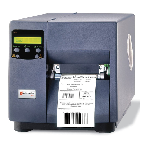
Overview 1.1 About the Printer The following drawing highlights the user-assessable components of the printer. Access Cover Ribbon Supply Hub Ribbon Take-Up Hub Media Hub Front Panel Printhead Assembly Fill Block Internal Rewinder Printhead Leveling Cam Media Sensor Printhead Latch Ribbon Idler Platen Media Idler... -
Page 9: Table Of Contents
Adjustments and Maintenance Introduction ..................1 Media Sensor Calibration ..............1 2.1.1 Quick Calibration ................ 1 2.1.2 Standard Calibration ..............2 2.1.3 Advanced Entry Calibration ............4 Printhead Adjustments ................. 8 2.2.1 Leveling Cam Adjustment ............8 2.2.2 Pressure Adjustment ..............9 2.2.3 Burn Line Adjustment .............. - Page 10 Application Version Updates ..............21 2.5.1 Updating from READY..............22 2.5.2 Updating from Download Mode ........... 23 2.5.3 Resolving Update Issues ............24 Boot Loader Program Updates ............. 25 Resetting the Printer ................26 2.7.1 Soft Reset................26 2.7.2 Level One Reset ............... 26 2.7.3 Level Two Reset ...............
-
Page 11: Adjustments And Maintenance
Adjustments and Maintenance 2.0 Introduction This section covers the necessary maintenance and alignment procedures for the printer. 2.1 Media Sensor Calibration This printer can use many different media compositions, configurations and colors. In addition to adjusting the Media Sensor and selecting the SENSOR TYPE, calibration is required. There are three different calibration methods. -
Page 12: Standard Calibration
Adjustments and Maintenance 2.1.2 Standard Calibration During calibration, the printhead assembly can be raised for visual access, which can be helpful when using small, position-critical TOF notches or marks. Three sample readings are required: Empty: No media in the sensor. •... - Page 13 Adjustments and Maintenance Step Action Displayed Message Comment Proceed according to the media type: Die-cut – peel media from • the backing and place the backing under the Sensor SCAN BACKING Never position a perforation Eye Mark then press the PRESS ESC KEY <yyy>...
-
Page 14: Advanced Entry Calibration
Adjustments and Maintenance 2.1.3 Advanced Entry Calibration Advanced Entry is the alternate calibration method for special-case media types. In the procedure, sensor readings for the label and TOF values are taken using different sampling algorithms. From this compiled list of values the best algorithm is selected and then used to generate new readings for manual entry into memory. - Page 15 Adjustments and Maintenance Step Action Displayed Message Comment GAIN TRAN <yyy> Use the Key to scroll to <0 - 31> Selection is denoted by an the 00 GAIN setting and then asterisk (*). press the Key. Or, for reflective media: The sensor reading equals Record the sensor reading as a the “yyy”...
- Page 16 Adjustments and Maintenance Sampling Table Gain Label Difference Number Value Value Value … … Step Action Displayed Message Comment GAIN TRAN <yyy> Press the Key to <0 - 31> increment the Gain Number then press the Key and record the resulting TOF Value. Or, for reflective media: Repeat this step for each of the GAIN REFL...
- Page 17 Adjustments and Maintenance Step Action Displayed Message Comment GAIN TRAN <yyy> <0 - 31> Using the Key, scroll to the Gain Number determined in Or, for reflective media: Step 12, and then press the Key. GAIN REFL <yyy> <0 - 31> a) Place the media in the sensor.
-
Page 18: Printhead Adjustments
Adjustments and Maintenance Step Action Displayed Message Comment After all entries have been made, press the to back out of the menu and Press and hold the SAVE CHANGES? then press the Key to ENTER KEY = YES save the settings when Key until at least prompted. -
Page 19: Pressure Adjustment
Adjustments and Maintenance Example 1 – Example 2 – Over-adjustment Correct adjustment produces an image produces a complete that fades across the image, with even label, requiring a print contrast across decrease in the setting the label. of the Leveling Cam. Note: Under-adjustment can cause ribbon wrinkling, tracking problems, and excessive wear on ... -
Page 20: Burn Line Adjustment
Adjustments and Maintenance 2.2.3 Burn Line Adjustment Note: This adjustment is NOT REQUIRED during a normal printhead replacement. The Burn Line, a row of thermal elements that creates the image, is adjusted to compliance using 6.5- mil (.0065 inch) media to maintain print quality across a majority of types. In extreme cases, however, when media with a different thickness or rigidity is used (e.g., heavy tag stock) this relationship can change. -
Page 21: Voltage Adjustment
Adjustments and Maintenance 2.2.4 Voltage Adjustment Voltage measurement required; use extreme caution. CAUTION The printhead voltage adjustment is required (1) when replacing the power supply or (2) if the factory voltage setting of the power supply has been changed. No voltage adjustment is required during a routine printhead replacement. -
Page 22: Ribbon Path Alignment
Adjustments and Maintenance NEVER exceed the recommended Printhead Voltage; permanent damage or shortened service life can result. WARNING Printhead Voltage Adjustment Table Printer Printhead Resistance Printhead Voltage Model (ohms) (+/- 0.1 Volt DC) 561 – 586 22.4 I4206, 587 – 611 22.9 612 –... - Page 23 Adjustments and Maintenance 1. Load 4 inch (102mm) or wider Media. 2. Load a matching Ribbon and allow it to feed with the Media from the printer. Ribbon Supply Hub Printhead Assembly Ribbon Media Idler Screw Idler Cam 3. Disengage the Leveling Cam; see Section 2.2.1. 4.
- Page 24 Adjustments and Maintenance 6. Attach the ribbon to the Take-Up Hub. Enter the Quick Test Mode and select 100 Quick Ribbon Test Labels then press TEST to begin printing. Take-Up Hub Printhead Assembly 7. Observe the ribbon for rippling and bagging as it travels from the Printhead Assembly to the Take- Up Hub.
-
Page 25: Maintenance
Adjustments and Maintenance 2.4 Maintenance This section details the items, techniques and schedules to help safely and effectively maintain the printer. The following cleaning items are recommended: Isopropyl alcohol • Cotton swabs • A clean, lint-free cloth • Lens tissue •... -
Page 26: Cleaning The Printhead
Adjustments and Maintenance 2.4.1 Cleaning the Printhead NEVER use a sharp object on the Printhead; damage can result. CAUTION If print quality declines (symptoms can include non-compliant bar codes or streaks in the image), the typical cause is debris buildup on the printhead. If not removed, debris buildup can result in permanent damage. -
Page 27: Cleaning Card Procedure
Adjustments and Maintenance 3. Allow the printhead to dry. 4. Install media (and ribbon, if necessary). Lower and latch the Printhead Assembly. Close the cover. Plug in and turn ON the printer. Run several sample labels and examine the print quality. If streaks are still present, go to Section 2.4.1.2;... -
Page 28: Cleaning Film Procedure
Adjustments and Maintenance 2.4.1.3 Cleaning Film Procedure This cleaning method is recommended when using thermal transfer media with a resin ribbon, a HEAT setting of 22 or higher, or if symptoms persist after performing the other cleaning procedures. 1. Turn OFF and unplug the printer. Wait for the printhead to cool. 2. -
Page 29: Cleaning The Media Path, Media Sensor, And Interior
Adjustments and Maintenance 4. Install media then lower and latch the Printhead Assembly. 5. Close the cover. Plug in and turn ON the printer. Feed several labels to normalize tracking. 2.4.3 Cleaning the Media Path, Media Sensor, and Interior As paper dust and other contaminants accumulate inside the printer, the particles can be pulled through the Media Sensor to the printhead, causing inconsistent label detection and voids in the print. -
Page 30: Cleaning The Ribbon Path
Adjustments and Maintenance 3. Using compressed air or a soft brush, remove all debris from the Baseplate and the Media Sensor. 4. Using a cotton swab dampened with isopropyl alcohol, wipe the Media Idler, Media Guide and, if attached, the Tear Bar or Rewind Plate clean. 5. -
Page 31: Cleaning The Exterior Surfaces
3. Allow the surfaces to dry. 2.5 Application Version Updates As available, application program (firmware) updates can COMMUNICATIONS CONFIGURATION be found at http://www.datamax-oneil.com/ and then SERIAL PORT A: TUE 09:09 AM 29JUL2008 installed. BAUD RATE: PRINTER KEY: 4308-TB10-020312-001... -
Page 32: Updating From Ready
Adjustments and Maintenance 2.5.1 Updating from READY Application Version 2.091 (or greater) Update Procedure Step Displayed Message Action Comment(s) As an example, this would be entered as: Using the DOS copy command (where “filename” is the copy i4212_1105.zg lpt1 program to be loaded and “lpt1”... -
Page 33: Updating From Download Mode
Adjustments and Maintenance 2.5.2 Updating from Download Mode Application Version 2.08 (or less) Update Procedure* Step Displayed Message Action Comment(s) The Boot Loader version is Turn OFF the printer. displayed. BOOT–PA10 Press and hold the PAUSE Key Note: This information will 02.08 2/11/00 ... -
Page 34: Resolving Update Issues
If experiencing trouble when downloading application updates to the printer, try an alternate method: Use Download Mode (see Section 2.5.2); or, • Use the Datamax-O’Neil Printer Driver to send the file. • If an error message appears during the updating process, locate it in the following table along with the... -
Page 35: Boot Loader Program Updates
2.6 Boot Loader Program Updates The printer stores its Boot Loader program in Flash memory. As available, updates can be found on our web site at http://www.datamax-oneil.com/ and then installed. If power is lost while UPGRADING SOFTWARE is displayed, the printer will become non-functional and will require factory reprogramming of the Main Logic PCB. -
Page 36: Resetting The Printer
Adjustments and Maintenance 2.7 Resetting the Printer Depending upon the method used, there are three reset levels possible: 2.7.1 Soft Reset To reset the printer and clear any temporary host settings, press and hold the CANCEL Key for approximately four seconds. 2.7.2 Level One Reset To return the printer to the factory default settings or, if saved, to restore the Factory Setting File:... - Page 37 Troubleshooting Overview .................... 1 Troubleshooting................... 1 3.1.1 Initial Steps ................1 General Problem Resolution..............1 3.2.1 Problem Isolation................ 2 3.2.2 No Power................... 3 3.2.3 No Print..................4 3.2.4 Poor Print Quality................ 5 3.2.5 Communications Problems ............6 Error Resolution................... 7 3.3.1 Warning Messages ..............
-
Page 39: Overview
Troubleshooting 3.0 Overview This section covers techniques for isolating and correcting printer problems. 3.1 Troubleshooting Use the following procedures to isolate and correct malfunctions. When problems are isolated to a Printed Circuit PCB (PCB), assembly replacement is suggested, as component level repair is not generally feasible in the field. -
Page 40: Problem Isolation
Troubleshooting 3.2.1 Problem Isolation Ensure that AC line voltage is within the operating range for the printer, and that the unit is installed in an acceptable Go to Step 2. environment. Turn ON the Power Switch. Did the printer power up? Go to Section 3.2.2 Load media (and ribbon if necessary). -
Page 41: No Power
Troubleshooting 3.2.2 No Power Note: (1) Ensure the AC outlet is functioning properly, with the power cord securely connected to the outlet and printer; and, (2) some printer circuits are protected by resettable fuses, when tripped cycling power will reset those fuses. Turn OFF the printer. -
Page 42: No Print
Troubleshooting 3.2.3 No Print Press TEST. Proceed according to the installed media type: Scroll to PRINT If using direct thermal media: CONFIGURATION, and Possible loose printhead assembly; latch it. then press TEST. • Possible wrong media; ensure type. • Is the resulting label blank? The HEAT setting may be too low;... -
Page 43: Poor Print Quality
Troubleshooting 3.2.4 Poor Print Quality Note: (1) If printed results are uneven, light or splotchy try increasing HEAT or reducing PRINT SPEED as no further adjustments may be needed; (2) during the procedure below, synthetic media may not produce the intended results due to the requirements of the material; and, (3) in extreme conditions, over-temperature protection circuitry can interrupt printing. -
Page 44: Communications Problems
Troubleshooting 3.2.5 Communications Problems Note: If troubleshooting an Ethernet or USB equipped printer, refer to the documentation that accompanied the option. 1. Turn OFF the printer. Ensure an interface cable is properly Test completed. If the label format does connected between the host and not appear as expected, check the label printer then turn ON the printer. -
Page 45: Error Resolution
Troubleshooting 3.3 Error Resolution All functions are monitored during operation and when a problem is detected a corresponding message will be displayed. (If no message appears, see Section 3.2.) In the tables below locate the Displayed Message, the Description, and then use Solution (listed by probability) to isolate the malfunction. Note: Warning and Fault Messages are not displayed in Menu or Test Mode. - Page 46 Troubleshooting Warning Messages (continued) Displayed Message Description Solution A small difference This is typical of labels mounted on a exists between the GAP MODE transparent backing, or of notched media. A measured “empty” and WARNING LOW BACKING slight delay in OUT OF STOCK detection may be “gap”...
-
Page 47: Fault Messages
Troubleshooting 3.3.2 Fault Messages Fault Messages receive the highest display priority and, if multiples occur, messages will cycle. Note: To return operation after a fault, correct the condition and then press FEED. Fault Messages Displayed Message Description Solution An analog to digital Attempt to clear the fault by cycling the power OFF ADC FAULT converter failure... - Page 48 Troubleshooting Fault Messages (continued) Displayed Message Description Solution Press any key to continue. Then, retry STANDARD CALIBRATION, ensuring that media is inserted at the appropriate step (see Section 2.1.2). If this fails, try ADVANCED ENTRY (see Section 2.1.3). If the problem persists, it can be due to one of following reasons: Consistently low 1) The media is transparent;...
- Page 49 Troubleshooting Fault Messages (continued) Displayed Message Description Solution Ensure correct media loading and Media Sensor adjustment. Then, if the problem persists, it can be due to one of following reasons: 1) The PAPER OUT DISTANCE may need to be increased. No media is OUT OF STOCK detected.
- Page 50 Troubleshooting Fault Messages (continued) Displayed Message Description Solution Press any key to continue. Retry the STANDARD CALIBRATION, ensuring that media is removed during the appropriate step in the procedure (see Section 2.1.2). If the problem persists, it can be due to one of following reasons: Consistently high REFLECTIVE MODE...
- Page 51 Troubleshooting Fault Messages (continued) Displayed Message Description Solution Press FEED to clear the fault. Examine the failed bar code and then if it is free of voids, with sufficient quiet zones, try the following: Ensure that the cabling from the scanner to the Centerplate to the Backplane PCB is firmly connected.
- Page 52 Troubleshooting Fault Messages (continued) Displayed Message Description Solution Turn OFF the printer. Then, when cooled, turn ON the printer. If the problem persists, it can be due to one of following reasons: A high printhead 1) The location may be too hot; move the printer to a TEMPERATURE temperature has place that does not exceed 100°F (38°C) ambient.
-
Page 53: Hex Dump Mode
After sending a label format to the printer, the output will be immediate and in the form shown below. As a final note, many software programs use bit mapping to construct the label making diagnosis difficult. Contact Datamax-O’Neil Technical Support with any questions. - Page 54 Troubleshooting To print a Hex Dump, load four-inch wide media (and ribbon, if thermal transfer printing) then proceed according to the type: Turn ON the printer. Enter DIAGNOSTICS and enable HEX DUMP MODE. Exit the menu and save • the changes. Note: To exit Hex Dump Mode, enter DIAGNOSTICS and disable HEX DUMP MODE then exit ...
- Page 55 Removal and Replacement Introduction ..................1 Cover Assembly................... 1 Front Panel ..................2 4.2.1 Front Panel PCB................. 4 Platen ....................5 Printhead.................... 7 4.4.1 Printhead Assembly..............9 4.4.1.1 Head Pressure Cams and Springs ......... 11 Thermal Transfer Assembly ..............13 4.5.1 Ribbon Supply Hub ..............
- Page 56 4.11 Main Logic PCB .................. 27 4.12 Backplane PCB .................. 29...
-
Page 57: Introduction
Removal and Replacement 4.0 Introduction This section details removal and replacement methods for various printer components; where multiple equipment types or options are available, use the procedure that best matches the configuration. Always disconnect AC power before performing service; ... -
Page 58: Front Panel
Removal and Replacement 3. Remove the two Screws that secure the Cover Assembly to the Baseplate, and then lift the Cover Assembly off the printer. Baseplate Screws Replacement: 1. Lower the Cover Assembly onto the printer. 2. Reinstall the two Screws through the Cover Assembly and into the Baseplate. 3. - Page 59 Removal and Replacement 3. Slightly bend the Tabs that extend through notches in the Centerplate and Baseplate then remove the Front Panel. Note: Use care when removing the panel from the Baseplate Notch, as Tab access is limited. Centerplate Front Panel Tabs Replacement:...
-
Page 60: Front Panel Pcb
Removal and Replacement 4.2.1 Front Panel PCB Removal: 1. Remove the Front Panel; see Section 4.2. 2. Slightly bend the Bezel Tabs, and then remove the Bezel (and Button Panel) from the Front Panel PCB. 3. Remove the two Screws that secure the Front Panel PCB to the Centerplate then disconnect the Front Panel Cable and remove the Front Panel PCB. -
Page 61: Platen
Removal and Replacement 4.3 Platen Removal: 1. Turn OFF and unplug the printer. 2. Raise the cover and remove the Fascia. 3. Raise the Printhead Assembly then remove the Thumbscrew and Tear Bar from the Platen Block. Printhead Assembly Platen Block Tear Bar Fascia... - Page 62 Removal and Replacement 5. Remove the two Screws that secure the Bearing Plate and then remove the Bearing Plate from the Platen Block. 6. Remove the Platen Assembly from the Platen Block. Platen Block Platen Assembly Replacement: 1. Place the Platen Assembly into the Platen Block, ensuring proper gear mesh. 2.
-
Page 63: Printhead
Removal and Replacement 4.4 Printhead Use extreme care when handling the printhead. If overvoltage is suspected, verify the supply voltage proceeding (see Section 2.2.4). CAUTION Removal: 1. Turn OFF and unplug the printer. 2. Raise the cover. With the Printhead Assembly lowered, loosen the Printhead Mounting Screw (it will remain in the assembly). - Page 64 Removal and Replacement Replacement: 1. Carefully reconnect both cables to the Printhead. 2. Position the Printhead onto the Locating Pins in the Printhead Assembly. Printhead Locating Assembly Pins Printhead 3. Secure the Printhead to the Printhead Assembly with the Printhead Mounting Screw, but do NOT over-tighten.
-
Page 65: Printhead Assembly
Removal and Replacement 4.4.1 Printhead Assembly Removal: 1. Turn OFF and unplug the printer. 2. Remove the Printhead; see Section 4.4. 3. Remove the two Screws that secure the End Cap to the Extrusion. 4. While supporting the Printhead Assembly, remove the End Cap, Wavy Washer, and Ribbon Idler. Centerplate Printhead Extrusion... - Page 66 Removal and Replacement 3. While holding the spring-loaded Printhead Assembly in the Centerplate bushing, place the Wavy Washer onto the (opposite) Printhead Assembly Boss. Printhead Assembly Boss Wavy Washer 4. Insert the Ribbon Idler shaft into the Centerplate bushing. 5. Reinstall the End Cap onto the Extrusion to captivate the Printhead Assembly Boss and Ribbon Idler shaft then secure the End Cap with the two Screws.
-
Page 67: Head Pressure Cams And Springs
Removal and Replacement 4.4.1.1 Head Pressure Cams and Springs Removal: 1. Remove the Printhead Assembly; see Section 4.4.1. 2. Carefully pry the Clip from the Printhead Assembly. Also, remove the two Screws that secure the Ribbon Shield and then remove it from the Printhead Assembly. Screws Ribbon Shield... - Page 68 Removal and Replacement 4. Carefully separate the Lower Carriage from the Printhead Assembly, compressing the spring- loaded assembly as necessary to separate the parts, and then remove the Alignment Springs. Alignment Springs Printhead Assembly Lower Carriage 5. Separate the Middle Carriage from the Upper Carriage then remove the Cams and the Pressure Springs.
-
Page 69: Thermal Transfer Assembly
Removal and Replacement Replacement: 1. Place the Pressure Springs and the Alignment Springs into the sockets of the Middle Carriage and place the Cams into the socket holes of the Upper Carriage then orient the Cam Indicators for least pressure (see below). Indicators 2. - Page 70 Removal and Replacement Centerplate Thermal Transfer Assembly Screws Replacement: 1. Inspect and if necessary wipe the Light Pipe clean using isopropyl alcohol and lens tissue (or lint free cloth). Light Pipe 2. Reinstall the Thermal Transfer Assembly in the Centerplate, carefully engaging the gears, and secure it using the three Screws.
-
Page 71: Ribbon Supply Hub
Removal and Replacement 4.5.1 Ribbon Supply Hub Removal: 1. Remove the Thermal Transfer Assembly; see Section 4.5. 2. Remove the Screw and Metal Washer that secures the Ribbon Supply Hub to the Housing. 3. Remove the Ribbon Supply Hub and Nylon Washer from the Housing. Housing Screw Ribbon... -
Page 72: Ribbon Take-Up Hub & Clutch Assembly
Removal and Replacement 3. Rotate the Ribbon Supply Hub until the Pin engages the Notch in the Housing. Housing Ribbon Supply Hub Nylon Washer Notch 4. Secure the Ribbon Supply Hub to the Housing with the Metal Washer and Screw. 5. -
Page 73: Rewind Assembly
Removal and Replacement Replacement: 1. Reinstall the Outer Bearing in the Thermal Transfer Housing. 2. Position the Take-Up Hub Clutch in the Thermal Transfer Housing 3. Slide the Take-Up Hub shaft through the Take-Up Hub Clutch and Thermal Transfer Housing. 4. -
Page 74: Rewind Hub, Clutch Assembly, And Spur Gear
Removal and Replacement Replacement: Reinstall the Rewind Assembly in the Centerplate, carefully engaging the gears, and secure it using the three Screws. 4.6.1 Rewind Hub, Clutch Assembly, and Spur Gear Removal: 1. Remove the Rewind Hub Assembly; see Section 4.6. 2. -
Page 75: Media Sensor
Removal and Replacement 3. Remove the Rewind Hub and the Outer Bearing from the Rewind Housing. 4. Remove the Rewind Hub Clutch from the Housing (and to remove the Spur Gear, remove the Screw that secures the Idler Post to the Rewind Housing). Replacement: 1. - Page 76 Removal and Replacement Media Idler 4. Pull the Media Sensor Guide and then the Media Sensor from the printer. Replacement: 1. Reinstall the Media Sensor and then the Media Sensor Guide. 2. Secure the Media Sensor Guide to the Post with the Screw. 4-20...
-
Page 77: Drive Motor Assembly
Removal and Replacement 3. Raise the lock then reconnect the cable to the Media Sensor. 4. Reinstall the Cover Assembly; see Section 4.1. 5. Perform calibration; see Section 2.1.2. 4.8 Drive Motor Assembly Proceed with removal and replacement of the Drive Motor Assembly depending upon the type. 4.8.1 Belt Drive Removal:... -
Page 78: Direct Drive
Removal and Replacement 4. Remove the four Screws that secure the Drive Motor to the Motor Mounting Block then slip the Belt off the Motor Pulley. Drive Screws Motor Motor Mounting Block Motor Pulley Motor Mounting Block Gear Belt Replacement: 1. - Page 79 Removal and Replacement 3. If replacing a 300 / 600 DPI model motor, remove the Front Panel (see Section 4.2); otherwise, proceed to Step 4. 4. Disconnect the motor cable. 5. Remove the two Screws that secure the Drive Motor to the Isolator (which also frees the Ground Cable Lug) and then remove the Drive Motor.
-
Page 80: Isolator
Removal and Replacement 4.8.2.1 Isolator Removal: 1. Remove the Drive Motor Assembly; see Section 4.8.2. 2. Depending upon the resolution of the printer, remove the Screws that secure the Isolator to the Centerplate Standoffs. Centerplate Standoffs (203 / 400 DPI) Isolator Screws Centerplate Standoffs... -
Page 81: Fuses
Removal and Replacement 4.9 Fuses Only use a replacement fuse with the rating and type as the original fuse; failure to comply could cause serious damage, including fire. Use caution when replacing Fuse F1, as this fuse will only blow during a failure in CAUTION the primary switching circuit and may indicate a more serious electrical problem. -
Page 82: Power Supply Pcb
Removal and Replacement 4.10 Power Supply PCB Removal: 1. Turn OFF and unplug the printer. 2. Remove the Cover Assembly; see Section 4.1. 3. Disconnect the cables from the Power Supply PCB. 4. Remove the two Screws and Nut Plate that secure the AC Connector. Connector Plate Screws... - Page 83 Removal and Replacement Replacement: 1. Position the Power Supply PCB in the printer then secure it with the four Screws. 2. Place the Washer onto the Screw, and then secure the Ground Wire Lug to the chassis with the Screw. 3.
- Page 84 Removal and Replacement 3. Remove the two Screws that secure the Main Logic PCB to the Card Cage. (In some cases it may also be necessary to remove the adjacent Filler Plate.) Filler Card Plate Cage Main Logic PCB Guides Screws 4.
- Page 85 Removal and Replacement 2. Insert the Main Logic PCB between the Guides in the Card Cage then slide it forward until seated. 3. Reinstall the two previously removed screws and secure the Main Logic PCB in the Card Cage. 4. Reinstall the interface cable(s). 5.
- Page 86 Removal and Replacement 6. Remove the four Screws that secure the Backplane PCB to the Card Cage and then remove the Backplane PCB. Card Cage Backplane PCB Screws Replacement: Proceed according to the Part Number of the Backplane PCB: If installing P/N 51-2311-00, ensure a Jumper is placed across E2 &...
- Page 87 Removal and Replacement If installing P/N 51-2348-00, configure the settings of the Jumpers according to the equipped options and default requirements: Scanner equipped: E1 & E2, E5 & • RFID equipped: E2 & E3, E4 & E4; • COM2 DTR Active (default): E7 & E8; •...
- Page 88 Removal and Replacement 3. Reconnect the cables according to the Part Number of the Backplane PCB. P/N 51-2311-00 P/N 51-2348-00 4. Replace the Main Logic PCB and the Filler Plate; see Section 4.11. Also replace any optional PCB removed from in the Card Cage. 5.
Need help?
Do you have a question about the I-class and is the answer not in the manual?
Questions and answers