Table of Contents
Advertisement
Quick Links
Download this manual
See also:
Programming Manual
Advertisement
Table of Contents

Subscribe to Our Youtube Channel
Related Manuals for GRAUPNER MC-32


Summary of Contents for GRAUPNER MC-32
- Page 1 33032. HoTT.3.en mc-32 mc-32 Programming Manual Programming Manual...
-
Page 2: Table Of Contents
Table of contents Shortcuts ............32 General notices Changes ............. 77 Warning notices in the display ......33 codes« ..........80 »Suppress Warning and note symbols ......... 3 Function fields in the display ........ 34 models« ..........81 »Suppress Safety notices ............4 Entry lockout ............ -
Page 3: General Notices Warning And Note Symbols
Warning and notice symbols and their meaning channels« ........163 »Channel sequence« ........... 262 WARNING: »Non-delayed (general)« ..........164 »Timers »Multichannel« ............. 264 This symbol highlights the adjacent or follow- »Flight phase timers« .......... 168 »Ring Limiter« ............268 ing instructions, which absolutely must be What is a mixer ............ -
Page 4: Safety Notices
If necessary, send the device This remote control system may only be sion. concerned to your local Graupner Service Centre; used for the purpose intended by the see page 343. All motor-driven parts, such as aircraft or ship propel- manufacturer, i.e. - Page 5 equipment. Under no circumstances may a servo Pay attention that no metal parts, e. g. as a result of before switching off the receiver, disconnect the cable be wrapped around the antenna or routed close rudder actuation, vibration, rotating parts, etc., rub model’s power supply to prevent the motor from rev- to it.
- Page 6 Graupner RC main catalog or in Internet at of the model. In this case your only recourse thereafter connect the charger cable’s plugs to the www.graupner.de.
- Page 7 • Never program the transmitter or receiver while Always supply power to an electric ignition system Graupner is found to be subject to unlimited liability the model is being operated. from a separate, dedicated battery. pursuant to binding legal stipulations with respect to...
-
Page 8: Safety Notices And Handling Regulations For Lithium-Ion (Liio) And Lithium-Polymer (Lipo) Batteries
Furthermore, Graupner to charge and discharge LiIo-/LiPo bat- an otherwise typical balancer plug connection, disregard for instructions and warnings can lead to teries, refer to page 18 or www.graupner.de. - Page 9 In the vicinity of, or while Damaged or useless cells are hazardous waste items Storage handling, Graupner LiIo-/LiPo batteries, avoid and must be appropriately disposed. LiIo-/LiPo cells should have a 10 … 20 % electrically conducting surfaces because of the General warning notices charge capacity when stored.
-
Page 10: Environmental Protection Notices
This manual serves only as a source of infor- mation and can be changed without prior noti- fi cation. Graupner accepts no responsibility or liability for errors or inaccuracies which may be con- tained in the information section of this manual. - Page 11 Remote control set description...
- Page 12 (rudder, eleva- quickly become familiar with the various functions and developed by Graupner is a synthesis of know-how, tors) and helicopter models (swashplate). Thanks to able to use all options pertinent to his level of exper-...
-
Page 13: Remote Control Set Description
2,4-GHz-Graupner-HoTT technology (Hopping Telemetry Transmission) • Integrated Graupner HoTT 2.4 GHz transmission system • The high-speed primary processor is used for data transfer, ensuring ultra-fast response times. No additional delays through detours via a module processor. - Page 14 Computer System mc-32 32 channel remote control set in 2.4 GHz Graupner-HoTT technology (Hopping Telemetry Transmission) • As many as four servos can be controlled simulta- As many as four servos can be controlled simulta- • Auto-trim function. The current stick positions Auto-trim function.
- Page 15 Additional functions into the receiver for every individual servo channel model can be entered here. This additional in- can be set separately formation will then appear in the newly designed • Super Fast response time by using the fast main model select function •...
-
Page 16: Technical Data
Computer System mc-32 32 channel remote control set in 2.4 GHz Graupner-HoTT technology (Hopping Telemetry Transmission) The set, No. 33032, includes The set, No. 33032, includes Technical data for the Technical data for the HoTT transmitter HoTT transmitter Technical data for the GR-32 Dual HoTT receiver... - Page 17 For your notes...
-
Page 18: General Operating Notices Transmitter
Transmitter power supply Charge the transmitter battery with the plug-in charger. Switch off the transmitter before opening it mc-32 HoTT transmitter is equipped with a (power switch to »OFF«). Push both housing high-capacity, rechargeable LiIo 1s6p/6000 3.7 V The transmitter's rechargeable LiIo battery can be base latches in the opposite the direction of TX battery (No. -
Page 19: Recommended Chargers (Accessory)
No. 3021 is additionally needed for the receiver. Other charger units and details about the listed chargers can be found in the Graupner RC main catalog or in Internet at www.graupner.de. The charger socket is equipped standard with a diode to protect against reversed polarity. -
Page 20: General Charging Notices
Lithium battery CR 2032 General charging instructions Stick length adjustment On the side of the transmitter board opposite the • Follow the charging instructions of the The length of both sticks can be continuously ad- transmitter battery there is a fi xture containing a charger manufacturer and battery manu- justed to adapt these transmitter controls to the pilot's lithium battery, type CR 2032, which can be replaced... -
Page 21: Stick Conversions
Stick conversions Brake spring and ratchet Stick restoring force The outboard screw of the two marked in the next The stick's restoring force can also be adjusted to the Neutralization fi gure adjusts the braking force and the inboard screw pilot's preference. -
Page 22: Transmitter Neckstrap Support Bars
The following straps are available as accessories: housing from the inside. Description Accessory switches, potentiometers, etc. are fastened 71.26 Transmitter straps, Graupner HoTT into place by screwing a nut onto the threaded shaft 72.40 Transmitter straps, deluxe protruding though the housing and tightening it with a suitable wrench. -
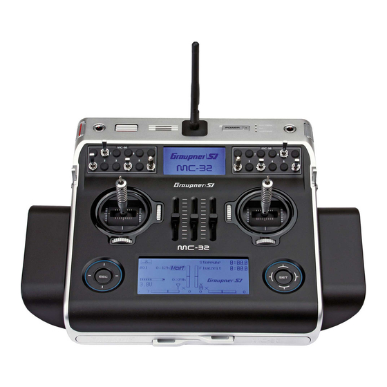
Page 23: Transmitter Description Front Side
Transmitter description Front side Antenna LC Display (more details available on page 30.) ON/OFF switch (ON/OFF with LED display) Telemetry indicators: receiver parameters, removable antenna, with kink and twist joint Note: standard. Other indicators dependent on the standard. Other indicators dependent on the Always switch on the transmitter then the receiver. -
Page 24: Face-Side Connectors
(No. 32032.4). plugging in the respective cable. mc-32 Maximum permissible charging current with Graupner The standard two-pole DSC jack in the 3. Connect the other end of the cable to the desired automatic chargers: 1.5 A. -
Page 25: Mini Usb Connector
The USB cable, No. 32032, which is included with the Details about the Smart-Box can be found with the set is to be connected to this jack. The procedure for given product in the Graupner RC main catalog or in carrying out a software update via Internet at www.graupner.de. -
Page 26: Card Slot
PC or laptop. There is a PC program available on the trans- 0:00h mitter’s download web page at www.graupner.de with 4.1V RX VOLT 4.8V which the stored data can be evaluated on a compat- ible PC. -
Page 27: Headset Connector
Once the right face-side cover has been moved away, An external RF module, for example a WEATRONIC • Any claims will not be considered mc-32 HoTT transmitter's headset connector is module, can be connected to this jack, see illustration without the presence of a log fi le. -
Page 28: Spi
The designation "SPI" stands for an interface for future applications. This socket is currently non-func- tional and may not be connected. Transmitter description - Face-side connections... -
Page 29: Bottom Side Transmitter Interior
Bottom side transmitter interior Notes: Disconnect the transmitter battery at its connector when performing any type of work inside the transmitter. Never allow solder points to come into contact with objects as this can create short circuit conditions. All jacks and plugs ot described are to INT PPM plug-in location be left unconnected. -
Page 30: Display And Keypad
Transmitter operating time. This will automatically be reset to zero after a Circle with the fi nger around the circumference charging process. charging process. = scroll/change values. Alternative values Graupner|SJ logo or Graupner|SJ Graupner|SJ logo or Graupner|SJ logo or Graupner|SJ selection with the left touch pad (, , , ) -
Page 31: Operating The "Data Terminal
Operating the "data terminal" Entry keys ESC and SET Display symbols Displayed telemetry symbols Keys to the right of the display • the active model memory has not yet been 1. After switching the transmitter on, a brief tap "bound" to a HoTT receiver. More about the on the key will cause a jump from the "Binding"... -
Page 32: Shortcuts
Shortcuts Entry lockout The following key combinations can be used to di- • Model select Copy / Erase rectly call up certain menus and options: Entry lockout is activated and deactivated from the Supress codes Supress models CLEAR • base screen by simultaneously touching the keys for about 2 s. -
Page 33: Warning Notices In The Display
Warning notices Warning notices sound. If the transmitter is now still not actuated Prompt to switch off RF switches transmission Batt. must • If battery voltage is too low, a model switch is transmitter operating volt- MUST BE be re- (A bound receiver can only blocked for reasons of safety. -
Page 34: Function Fields In The Display
HoTT transmitter is in its basic display. This lockout condition is indicated by a key symbol, located at the intersection point of the trim bars, which is displayed in reverse video. -
Page 35: Hidden Mode
VOICE_SPAIN.VDF either with the PC program available as a download VOICE UPDATE from the transmitter's web page at www.graupner.de FIRMWARE UPDATE Now use the keys of the left or right touch pad to or with the SD card, as described below. If not already... -
Page 36: Change Of Display Language
Appropriate updates and information can be found on mc-32 HoTT transmitter's product page under the Download link at www.graupner.de. When this process is fi nished, switch off the transmitter. … then the transmitter could not fi nd an FILE LIST appropriate fi le on the inserted memory card. -
Page 37: Stick Calibration
STICK CALIBRATION … will appear. After a few seconds this message will Firmware Download be erased and the transmitter will automatically re- If you feel the neutral position of your self-centreing Prozess Start start. The transmitter is now again operational. ... - Page 38 –50 S E C R E T M O D E STICK CALIBRATION BOTTOM LCD CONTRAST VOICE UPDATE FIRMWARE UPDATE STICK CALIBRATION +102% One after the other, put both sticks into each of their ... then briefly touch the centre key of the right …...
-
Page 39: Bluetooth Initialization
Bluetooth initialization Proceed similarly to calibrate the three sliders mount- ed in the middle console and the two proportional S E C R E T M O D E rotary controls on the sides of the transmitter. The calibration options for these five proportional controls VOICE UPDATE can be reached by repeatedly tapping on the ... -
Page 40: Telemetry Data Display
… which will be replaced shortly thereafter with the plays described below must be accepted if they have keys of the left or right touch pad … Graupner|SJ logo and the transmitter names … been properly connected before turning on the receiver RX–S QUA: 100%... - Page 41 More details about the following named modules BAT1 E FUEL F last startup, in volts can be found in the appendix and in Internet at 0.0V www.graupner.de in the web page for the given prod- POWER the thermometer depicts the receiver's 0°C 0.0V uct.
- Page 42 Battery and load indicators An alternating display along the screen's right edge If attached, this display depicts currently measured will display a list of current cell voltages for a LiPo voltage and temperature from a temperature/voltage 0.0V sensor, No. 33612 or 33613, connected to "T(EMP)2" battery with up to six cells or operational data (current altitude with respect to the starting location, ascent/ of the General-Engine module (No.
- Page 43 Electric-Air module, No. 33620. Micro-copter display More details about this module can be found in the 0.0V Alt: CELL0=0.00V appendix or in Internet at www.graupner.de in the 0:00 Dir: 0° web page for the given product. 0mAh...
- Page 44 This display visualizes the data of an HoTT compat- SENSOR 1 Speed display ible microcopter. It means from left up to right down: SENSOR Value Explanation 0.0V current voltage km/h 0°C „0:00“ Power on time Capacity used in actual power on time „0“...
- Page 45 VARIO Micro-copter display Vario 0.0V Alt: RX–S QUA: 100% RECEIVER RX–S ST : 100% 0:00 Dir: 0° RX–dBm: 33dBm GENERAL 0mAh TX–dBm: 33dBm ELECT. AIR V–PACK: 10ms VARIO 0km/h 0° RX–SPG.:4.8 CH OUTPUT TYPE:ONCE If attached, this display will depict altitude relative to This display visualizes the data of an HoTT compat- m/1s RXSQ...
- Page 46 10ms With firmware version 1.072 the GPS VARIO In the blank in the above figure line of the display any functionality of the mc-32 HoTT was RX–SPG.:4.8 messages Microcopter sensors display. CH OUTPUT TYPE:ONCE expanded: Once out of what ever reason, the...
- Page 47 Vario Rotary speed sensor This display visualises the data from a possibly con- nected to the receiver brushless controller with in- ternal telemetry with one of the time of the revision of these instructions current No. 33718-33770 and 33850th U/min Regardless of any regulator values the operating tem- perature and the maximum temperature reached in the current energizing period of a telemetry-capable...
-
Page 48: Commissioning The Transmitter
Graupner-HoTT receiver but there is no connection to ting frequencies with other pilots in the vicinity (which the right touch pad.Within this brief period there is an that receiver at the moment. - Page 49 Save mode, see page 2248, i. e. servos attached to the standard receiver will remain in their current positions included with the mc-32 HoTT until a new, valid signal can be received. 2.4 GHz Set. The specific receiver In such a case, increase the distance...
-
Page 50: Transmitter Firmware Updates
... By means of a PC or laptop running Windows XP, should become necessary. the relevant product on www.graupner.de. Vista, 7 or. 8 • It is essential not to disconnect the Download as described above, a recent update of the... -
Page 51: Restoring The Transmitter Software
Restoring the transmitter software If a firmware update of the station have failed, or the transmitter software “hang” and allows the transmitter may also no longer on the “POWER” switch off, then please disconnect the transmitter battery connector and plug it after a few seconds. Leave the transmitter off! Download in this case download an actual software package from the Internet and unzip it on your PC or... -
Page 52: Receiver Initialization
(default value -10 °C) or rise look for notices about this in the instructions for link to a Graupner HoTT transmitter. If a link has been above an adjustable threshold (default value +55 °C), the speed controller used. -
Page 53: Receiver Firmware Updates
Therefore if a RESET is triggered uninten- unnecessary. Note: tionally, any custom settings that had been For this program the default to mc-32 HoTT After registering your receiver at present in the receiver before the reset will transmitter set (No. 33032) is included USB interface https://www.graupner.de/de/service/... -
Page 54: Installation Notices
Only when servo fastening screws are properly , no specially designated connection for power supply tightened will this arrangement provide security Regardless of which Graupner receiver system you is available, so that the battery can generally be con- and vibration protection for your servos. The figure use, the procedure is always the same. -
Page 55: Receiver Power Supply
Servos present another possible problem source. Under no circumstances may be connected across Even rather small servos like a Graupner/JR DS-281 the other terminals 1 to 12 components and espe- can draw up to 0.75 A of current when it is blocks un- cially the receiver battery as shown demonstratively der load. - Page 56 1400 mAh would be the absolute minimum to power supply, stabilized found in the Graupner RC main catalog or in Order No. 4136 a receiver system with a total of 4 analog servos. But Internet at www.graupner.de.
- Page 57 Charging the receiver battery present a problem for either Graupner HoTT receiv- ers nor for those servos, speed controllers, gyros and Charger cable, No. 3021, can be plugged directly onto other devices which have been specifically approved the receiver’s battery for charging. If the battery in for operation in this –...
-
Page 58: Definitions Of Terms
Term definitions Control function, control, function input, control channel, mixer, switch, control switch, fixed switch To make use of this mc-32 HoTT manual easier, a • the three proportional sliders in the middle console e. g. in the Heli type “3sv (2Roll)” the control function number of the terms used repeatedly throughout this designated Sl1 …... - Page 59 the physical control's course of travel by the touch of a key. The switching action can be correlated to the physical control's travel direction by software. Of course control switches can also be freely com- bined with the aforementioned physical switches to solve even more complex problems.
-
Page 60: Physical Control, Switch And Control Switch Assignments
Principle procedure Notes: Changing switch action Maximum fl exibility is offered by the mc-32 Hott The control will only be recognized beyond a system when it comes to assigning standard equip- If the activation of a switch is to result in the oppo- certain amount of travel. - Page 61 Notes: • Automatic switch on/off of the timer to measure pure "flight time" for a helicopter by way of a • Switching for some special functions may control switch on the throttle limiter. be better implemented from a certain freely programmable control position •...
-
Page 62: Digital Trim
»Trim memory« menu. • The "cut-off trim" function, known from other Graupner remote control systems in the mc and If flight phases have been created and each assigned with a fitting name in the »Phase settings« (page mx series, and typically described in this section can be realized with the help of the "Thr. - Page 63 For your notes...
-
Page 64: Winged Models
Winged models Convenient support is provided for up to four aileron If ailerons, and conditionally the flaps, are each actu- ailerons, rudder and elevators are separately pro- servos and four flap servos on normal models or, for ated with two separate servos then settings can be grammable and each are convertible between the two V tail and flying wing/delta models, up to two aileron/ made for differentiated control of all aileron and flap... -
Page 65: Receiver Layout
Installation notices … and tail plane type "V tail unit" Delta/flying wing aircraft models with and without motor having up to 4 aileron/elevator servos and SUMO / SUMI-connection Servos MUST be connected to the receiver up to 4 flap/elevator servos free or aux. -
Page 66: Servos In Wrong Direction
Because of orientation differences for installed ser- vos and their rudder linkages, the actuating direction of some servos may be initially backward. The table below provides remedies. Servo Model direction Remedy type wrong V tail Rudder and Reverse polarity of elevator reversed servos 3 &... - Page 67 For your notes...
-
Page 68: Helicopter Models
7. Pitch-axis throttle advantage of mc-32 HoTT features with increasing two variations in every flight phase. 8. Pitch-axis tail rotor expertise. -
Page 69: Receiver Layout
Notice for those transitioning from older Receiver allocation for helicopter models with Receiver allocation for helicopter models with Graupner systems: 1 to 3 swashplate servos 4 swashplate servos In comparison to previous receiver layouts, SUMO / SUMI-connection SUMO / SUMI-connection servo connector 1 (pitch servo) and servo free or aux. -
Page 70: Loading A New Memory Location
Detail program description Loading a new memory location Anyone who has worked through to this part of the On this view it can be seen that the receiver is “spe- Model select Copy / Erase manual has certainly already tried out a bit of pro- cific memory”... - Page 71 • After the selected model memory is initialized with … then move the throttle stick, or the limiter for a Afterward you will be prompted to select the basic the desired model type, the display will switch to helicopter, (by default this is the right rotary slider model type, i.
- Page 72 With either model type, this situation will only change B A S I C S E T T I N G S M O D E L after appropriate assignments have been made in the Model name »Control adjust« menu. Info On the other hand, if a newly initialized model mem- Stick mode...
-
Page 73: Model Select
Model select Call up model 1 … 80 Notes: The basic operation of the transmitters keys was Turn off this. explained on pages 30 and 31 and, on the previous • Firmware from V1101 • If, after a model change, the "Throttle too double-page, explanations were provided for navigat- high"... -
Page 74: Copy / Erase
Copy / Erase Erase model, copy model model, copy from or to SD card, copy flight phases, store/cancel changes Use the selection keys of the left or right touch If the message shown above should appear, the pad to select the »Copy / Erase« menu … transmitter’s RF module is still active. -
Page 75: Copy Model Model
Copy model model Exporting to SD card Yet another tap on the key will then confirm the copy process or a tap on key will cause the copy Select the “Copy model model” sub-menu with the Use the selection keys of the left or right touch to be cancelled. -
Page 76: Import From Sd Card
Starlet trim needed 00:33hR08 the memory card in the \\Models\mc-32 folder operation. BELL47G 00:22hR08 with a fi lename format of "aModelname.mdl" Choose contrast with the button left or right touch free ... -
Page 77: Copy Flight Phase
bound. then confi rmed with a brief tap on the key of the right touch pad. In the next window to appear … Copy fl ight phase model Select the “Copy fl ight phase” sub-menu with the Copy to phase: Extra 300 selection keys of the left or right touch pad then tap free... -
Page 78: Changes
Undoing changes To store changes permanently, select the appropriate line then briefly tap on the centre key of the right Assuming that you already have at least once touch pad. The confirmation request shown below will pressed “save changes permanently” option in the appear: active model memory, you can “undo changes”... - Page 79 Programmbeschreibung - Menüs ausblenden...
-
Page 80: Suppress Codes
Suppress menus Suppression of menus in the multifunction list Use the selection keys of the left or right touch In the menu which then appears, menu items which pad to select the »Suppress codes« menu … are no longer needed or those which should not be changed, can be blocked from appearing in the multi- Model select Copy / Erase... -
Page 81: Suppress Models
Suppress models Suppression of model memory locations Use the selection keys of the left or right touch Graubele 1234g/080811 01:23hR16 pad to select the »Suppress models« menu … Ultimate Test 00:44hR12 Model select Copy / Erase Starlet trim needed 00:33hR08 Suppress codes Suppress models... -
Page 82: Basic Settings, Model
Base setup model Model-specific base settings for winged aircraft models Stick mode Before programming specific parameters, there are !"#$%&’() +,–./0123456789:; some basic settings to be made which effect the cur- “MODE 1” (Throttle at right stick) “MODE 2” (Throttle at left stick) @ACDEFGHIJKLMNOPQRSTUVWXYZ[¥]^_ rently active model memory. -
Page 83: Binding Type
HoTT display of the receiver type in the menu “Model Info 1234g/111111 select”: To be able to connect to the transmitter, Graupner Stick mode HoTT receiver must be connected to at least one “Model” -specific bound receivers are inversely Model Binding type model memory “of their”... -
Page 84: Binding Receivers
Module HoTT bind whereby mc-32 HoTT programs offer the potential free binding channel. In the example shown in the BD1 BD2 BD3 BD4 for managing up to two receivers directly and for di- figure below, the marker frame is positioned above the viding up the transmitter’s 16 control channels (max) - Page 85 In this case the screen module". Afterward, return again to the "Module" line If your transmitter is fi tted with a non-Graupner exter- will continue to show the status as "n/a". If this and restart the binding process as described above.
- Page 86 Important notes: are all the HoTT-specific displays in the base display; 0:00.0 Graubele Stop watch “PPM” is also superimposed instead of “HoTT”: • The output voltage of the DATA 0:00.0 0:00h Flight time socket is around 5 V, and must be 0:00.0 Graubele Stop watch...
- Page 87 As mentioned in the introduction to the "Binding receiv- If, for example, "2AIL" has been specified in ers" section, this menu item of the mc-32 HoTT B A S I C S E T T I N G , M O D E L the "Aileron/camber flaps"...
-
Page 88: Range Test
(outputs) corresponds to the maximum Channel assignment on other receivers number of servos which can be attached to Perform a range test on the Graupner HoTT system ac- the given receiver. cording to the following instructions. If necessary, have As already mentioned, the "Rcv Ch map" menu op- someone assist you in carrying out the range test. - Page 89 C A N ‘ T … 5, for "PPM16" channels 1 … 8, for "PPM18" chan- Contact your area's Graupner service partner. R E C E I V E nels 1 … 9 and for "PPM24" channels 1 … 12.
- Page 90 The factory setting for the left column is -100 % for speed controller, alone by the switch to be assigned the"Cut-off trim" function known from other Graupner the throttle servo "cut-off" position and a threshold of in the right column.
- Page 91 In combination with logical switches, almost any At the instant the switch is activated, the stick offsets B A S I C S E T T I N G , M O D E L switch setting can be called up for transmitter switch from their neutral positions will be determined and RF transmit adopted as trim values.
-
Page 92: Helicopter Model
Base setup model Model-specific base settings for helicopter models Auto timer reset Before programming specific parameters, there are !"#$%&’() +,–./0123456789:; some basic settings to be made which effect the cur- B A S I C S E T T I N G , M O D E L @ACDEFGHIJKLMNOPQRSTUVWXYZ[¥]^_ rently active model memory. -
Page 93: Binding Type
A simultaneous tap on the or keys of the Note: This info note will appear as a supplement in the »Model select« menu and in the sub-menus of the right touch pad (CLEAR) will reset the display to •... -
Page 94: Binding Receivers
To be able to connect to the transmitter, Graupner viding up the transmitter’s 16 control channels (max) column label “BD2” because the binding channel in the... - Page 95 Press and hold the button on the receiver On the other hand, should the LED on the receiver Drop down two lines in the screen and switch off the while the LED continues to blink red for about blink red for longer than about 10 seconds, the RF module as described on the page in section “RF 3 seconds then, after about another 3 seconds, binding process has failed.
- Page 96 0:00h Flight time are all the HoTT-specific displays in the base display; If your transmitter is fitted with a non-Graupner exter- “PPM” is also superimposed instead of “HoTT”: H-J Sandbrunner nal RF module connected to the DSC / Data socket, you can switch between the standard internal HoTT 0:00.0...
- Page 97 “module”. 128 %. As mentioned in the introduction to the “Binding receiv- ers” section, this menu item of the mc-32 HoTT SP channels B A S I C S E T T I N G , M O D E L...
- Page 98 With the »Tx. output swap« option, available • Rx Input Ch Rx Output Ch on the mc-32 transmitter, see page 234, the Rx Input Ch Rx Output Ch After selection of the desired output with the selec- transmitter’s control functions can be interchanged...
-
Page 99: Range Test
100 m. about 50 m, try to reproduce this malfunction. Perform a range test on the Graupner HoTT system ac- 7. If there is a motor in the model, it may be necessary cording to the following instructions. - Page 100 Caution: Autorotation B A S I C S E T T I N G , M O D E L Never start the range test on the Autorotation is that state of descending flight in which RF transmit transmitter during normal operation the pitch of main rotor blades are set such that the RF range test of the model.
- Page 101 This option not only replaces the"Cut-off trim" function in section "Switches, controls and control switches": time throttle servo or speed controller movement known from other Graupner mc and mx transmitters beyond the preset threshold with the throttle/brake B A S I C...
- Page 102 One of the two standard momentary contact switches B A S I C S E T T I N G , M O D E L B A S I C S E T T I N G , M O D E L mounted into the switch panels should be the pre- DSC Output PPM10...
- Page 103 Power-on warning The "Auto trim" option makes it possible to trim a • Never send a “normal” toggle the Auto- model quickly and without complications, e. g. in the trim function to or watch out embarrass- B A S I C S E T T I N G , M O D E L context of a first-flight or even after (major) repairs, etc.
-
Page 104: Model Type
Model type Establishing winged aircraft model type Tail type This "Model type" menu is used to establish the type The warning "Throttle too high", see page 33, is of model to be programmed. This also activates all deactivated and the "Brake settings" sub-menu of the After selecting the »Tail type«... - Page 105 "Delta/fl": Brake Offset Available Control channel used Aileron and elevator control is operated by one or two This function not only has potential for gliders and 1AIL servos per wing half. However, elevator trimming is electric models but also for models with combustion 1AIL 1FL 2 | 6 also affected by selecting the "2AIL 2FL"...
- Page 106 • Brake offset values with a "-" prefix will cause flaps affected by the "Brake settings" option of the »Wing mixers« menu (see page 185) to be extended when the C1 stick is moved from rear to front, in the direction away from the pilot. If the offset point is not set at the far end of control el- ement travel, the remainder of travel to the end point will be "free travel", i.
- Page 107 Für Ihre Notizen...
-
Page 108: Helicopter Type
Helicopter type Establishing helicopter model type This "Model type" menu is used to establish the type Two roll servos will displace the swashplate H E L T Y P E of model to be programmed. This also activates all axially to affect pitch control; nick control will be Swashplate type 1 Ser vo characteristic mixers, coupling functions, etc. - Page 109 Symmetric three-point control as described above The "yes" entry will prevent undesired side effects but radially offset by 90°, one lateral roll servo and such as pitch change due to a roll function or tension two pitch-axis servos, front and rear. between swashplate servo rods.
- Page 110 adjust« menu with which the throttle servo can The “Pitch min.” line is used to adapt the actuation slider – also regulate the idle setting. Further details direction of the throttle/pitch stick to personal control be limited, independent of the pitch servo, in the about the throttle limit can be found in the text for the »Control adjust«...
- Page 111 Program description - Helicopter type...
-
Page 112: Servo Adjustment
Servo adjustment Servo direction, midpoint, travel and limit This menu is used to set the direction, neutralization, 3. Briefly tap the centre key of the right touch Servo direction Stick direction travel and limit parameters for a given selected servo pad. - Page 113 Column 4, "–travel+" A simultaneous tap on the or keys of the To create a symmetric limit, i. e. control-side independ- right touch pad (CLEAR) will reset the changed pa- ent limit, the respective control (stick, proportional con- Servo 1 100% 100%...
-
Page 114: Stick Mode
Stick mode Setting stick mode 1 through 4 Trim Both sticks are equipped for digital trimming. When 0:00.0 Graubele Stop watch turning trim wheels, every "click" will shift the stick's Except for "Channel 1", this column can be used to 0:00.0 0:00h Flight tim... - Page 115 Time After selecting the "Tr. step" column (trim steps) and the desired trim control with the selection keys The rate of control signal change with respect to the of the left or right touch pad, the corresponding entry speed of stick motion can be influenced by the entries field will be framed.
-
Page 116: Helicopter Model
Stick mode Setting stick mode 1 through 4 Trim Both sticks are equipped for digital trimming. When 0:00.0 Starlet Stop watch turning trim wheels, every "click" will shift the stick's These setting variations are configured to accom- 0:00.0 0:00h Flight tim neutral position by a certain value. - Page 117 The time can be programmed symmetrically for both Pitch/thr Thr trim 0.0s 0.0s Pitch/thr Thr trim 0.0s 0.0s sides or separate for each control direction. This set- Roll global 0.0s 0.0s Roll global 0.0s 0.0s ting has a programmable range of 0 s to 9.9 s. In this latter case, the given stick control is to be moved to Pitch ax global...
-
Page 118: Control Adjust
6. A simultaneous tap on the or keys of the make it inactive, i. e. not assigned to any function. and their trim wheels, the mc-32 HoTT transmitter right touch pad (CLEAR) will any setting made All of the aforementioned operating elements can also has other controls as standard equipment: back to its respective default value. - Page 119 Now use the selection keys of the left or right touch pad +100% +100% 0.0 0.0 +100% +100% 0.0 0.0 to select the desired input out of the list if the respective +100% +100% 0.0 0.0 Move desired +100% +100% 0.0 0.0 plug-in location on the transmitter board is occupied...
- Page 120 A simultaneous tap on the or keys of the GL fr +100% +100% 0.0 0.0 +100% +100% 0.0 0.0 right touch pad (CLEAR) will reset the entry field Move desired switch +100% +100% 0.0 0.0 +100% +100% 0.0 0.0 value displayed in inverse video back to "0 %".
- Page 121 Notes: changed with the selection keys of the right touch pad. To set a symmetric, i. e. control-side independent, Suggestions for the structure of temporal time delay, the respective operating element (trans- +111% +111% 0.0 0.0 sequences, see “Controlling timed sequenc- mitter control or switch) is to be put into a position in es”...
-
Page 122: Helicopter Model
In addition to the two sticks for control functions 1 to 4 selection from among "additional" operating elements pad to open this menu option: and their trim wheels, the mc-32 HoTT transmitter while, at the same time, not requiring the "deactiva- also has other controls as standard equipment: Firmware version V1102 and lower tion"... - Page 123 Column 2, "typ" The names assigned to given flight phases then ap- +100% +100% 0.0 0.0 pear in the second-from-the-bottom display line, e. g. Similar to the previously described »Stick mode« Thr6 Move desired +100% +100% 0.0 0.0 «Normal». menu, this column can be used to define whether Gyr7 control adj.
- Page 124 in its neutral position and can only be controlled via The display will now present the given switch number GL fr +100% +100% 0.0 0.0 mixers. together with a symbol indicating the given switch Thr6 Move desired switch +100% +100% 0.0 0.0 direction.
- Page 125 Column "offset" Important: +111% +100% 0.0 0.0 In contrast to altering servo travel, changing the The control centre for the given control, i. e. its zero Thr6 +100% +100% 0.0 0.0 control travel setting affects all "downstream" mixer point, can be changed in this column. The adjustment and coupling inputs, i.
- Page 126 Thr6 "Gyr7" +111% +111% 0.0 0.0 Thr6 +100% +100% 0.0 0.0 +111% +88% 0.0 0.0 +111% +88% 0.0 0.0 Gyr7 +100% +100% 0.0 0.0 Thr6 +100% +100% 0.0 0.0 Thr6 +100% +100% 0.0 0.0 +100% +100% 0.0 0.0 Gyr7 +100% +100% 0.0 0.0 Gyr7...
- Page 127 The centre point of the control corresponds to the If the model is flying forward at high speed or hov- setting specified by the offset. If the transmitter con- ering in a powerful headwind, the net result of the trol is moved from this centre point in the direction stabilizing effect of the vertical fin combined with the of full travel, gyro gain increases proportionally;...
-
Page 128: Throttle Limit Function
The "throttle limit" feature resolves this problem el- initializing a new model memory with the model type up" and one "without idle-up" – because the mc-32 egantly by using a separate transmitter control – by “Helicopter” is by default “free”:... -
Page 129: Idle Setting
Bear in mind that servo output 6 controls the trim wheel of the throttle/pitch stick and the motor or actuate the "Thr. CutOff" option, see page 101. the throttle servo on the mc-32 HoTT! is shut off by the "Thr. CutOff" option. Note:... - Page 130 • A servo connected to output 16 can be used, To set a delay time, push the throttle limit control to independently of this, for other purposes by its forward limit or move the switch into its full-throttle means of mixers, provided that this servo is position then use the selection keys of the left or right decoupled from the operating element specified by touch pad to select the "–time+"...
-
Page 131: Throttle Limit In Combination With Ar In The »Stick Mode Menu
Throttle limit in combination with "Thr AR" in the »Stick mode« menu As already explained on page 116, when "Thr AR" is In this case, with a completely closed throttle lim- selected in the "Pitch/thr" line of the … iter – in contrast to the previously described setting – use the »Control adjust«... -
Page 132: Dual Rate / Expo
Dual Rate / Expo Configurable control characteristics for aileron, elevator and rudder Expo, on the other hand, enables finer-grained con- Flight phase-dependent Dual Rate and Expo Use the selection keys of the left or right touch pad to scroll to the »Dual Rate / Expo« menu option in the settings trol of the model for values larger than 0 % around the Multi-function menu:... - Page 133 Dual Rate function Caution: Aileron 100% ––– If a switchover between two variants is desired, as- For safety reasons, Dual Rate value settings Elevator ––– 100% ––– sign a switch in the column labelled with the should not be less than 20 %. Rudder –––...
- Page 134 »Control switch« menu, see page 146, and a logical A simultaneous tap on the or keys of the Do not change the switching point for the stick's switch must have been appropriately defined in the right touch pad (CLEAR) will reset a changed entry neutral position (0 %).
- Page 135 Aileron ––– 100% ––– Elevator ––– Rudder ––– 100% ––– DUAL EXPO Normal … and "Down elevator": Aileron ––– 100% ––– Elevator 111% ––– Rudder ––– 100% ––– DUAL EXPO Normal Note: The vertical dashed line shows the current elevator stick position. Set the Expo values as necessary in the same man- ner.
-
Page 136: Helicopter Model
Dual Rate / Expo Configurable control characteristics for roll, pitch-axis, tail rotor Flight phase-dependent Dual Rate and Expo Use the selection keys of the left or right touch pad to The control travel for each switch position can be set scroll to the »Dual Rate / Expo«... - Page 137 Exponential function tom edge of the display in order to separately change Roll ––– 100% ––– the dual-rate values shown in inverse video for each If a switchover between two variants is desired, as- Pitch ax ––– 100% ––– of the two switch positions. Move desired switch sign a switch in the column labeled with the Tail rot...
- Page 138 Some examples of Expo values: Now, with a brief tap on the centre key of the Roll 100% right touch pad, activate the switch assignment and Expo = +100% Expo = +50% Expo = –100% Pitch ax ––– 100% ––– change to the expanded switches then use the selec- Tail rot –––...
- Page 139 Roll ––– 100% ––– Nick 111% ––– Tail ––– 100% ––– DUAL EXPO Normal Note: The vertical dashed line shows the current pitch axis stick position. Set the Expo values as necessary in the same man- ner. Program description - Dual Rate / Expo | Helicopter models...
-
Page 140: Channel 1 Curve Winged Model
Channel 1 curve Control characteristics for throttle/spoiler stick Using the selection keys of the left or right touch pad, If flight phases have been specified in the »Phase In the example above, the stick is at 0 % of control scroll to the »Channel 1 curve«... -
Page 141: Channel 1
As soon as the reference point number and its cor- been set. When a jump is made from one to another, Channel 1 C U R V E responding value on the "Point" line are displayed in the point value field for the jump's destination refer- inverse video, see figure above, these can be erased ence point in the screen's Point line will be displayed Trim offset... - Page 142 Smoothing the Channel 1 curve This process with a brief tap on the centre on the right or the centre key on the left touch In the example below, sample reference points have pad: been set: reference point 1 to 0 %, Channel 1 C U R V E reference point 2 to +25 % and...
-
Page 143: Helicopter Model
Channel 1 curve Control characteristics for throttle/collective pitch stick Using the selection keys of the left or right touch pad, The control curve can be defined by up to 8 points scroll to the »Channel 1 curve« menu option in the (termed "reference points"... - Page 144 Erasing reference points Trim point function Channel 1 C U R V E To delete one of the reference points (1 to max. 6), use Alternatively, jumping through set reference points can Trim offset the stick to move the vertical line into the vicinity of the be done with the ...
- Page 145 Smoothing the Channel 1 curve Channel 1 C U R V E In the example below, sample reference points have been set: reference point 1 to 0 %, Input –50% reference point 2 to +25 % and Curve Output reference point 3 to -75 % Point –...
-
Page 146: Switch Display
Control switches Switch display Programming the control switches Displaying switch positions Use the selection keys on the left or right touch pad This feature is used to check the functions and give Use the selection keys on the left or right touch pad to scroll to the »Switch display«... - Page 147 5th column. free ––– Using the selection keys on the left or right touch mc-32 pad, select your chosen line (1 to 8). Following a final HoTT program is equipped with a total free –––...
- Page 148 • In the above example with the switching direction Following a brief tap on the centre key of the C O N T R O L S W I T C H reversed, control switch "C1" remains closed while right touch pad, the switch direction can by changed Lever1 +85% –––...
- Page 149 Application Note regarding the inverted switches: C O N T R O L S W I T C H If you select an inverted switch during the In order to make these control switches usable, they Lever1 +85% assignment process – e. g. “G3i” instead of can be specifi ed in those menus which use switches “G3”...
-
Page 150: Logical Switches
Logical switches Programming logical switches • “AND” function Use the selection keys on the left or right touch pad Allocation of a switch to a logical function is done in to scroll to the »Control switch« option in the multi- the familiar manner in the columns labeled by the two The logical switch is only closed when both input function menu:... - Page 151 M wünschten Schalter Control/Logic/fix switch to die EIN Position (erw. Schalter: SET) FXi L1 Now use the selection keys to pick the desired control switch "C1 … C8", fi xed switch "FX" or logical switch "L1 … L8" or the respected inverted switch "C1i … C8i", "FXi"...
-
Page 152: How Do I Program A Flight Phase
– at particular times in the flight (e. g. take- programming flight phases. Two examples of flight »Dual Rate / Expo« off, approach, hover, auto-rotate, etc.). With mc-32 phase programming can be found in the text begin- HoTT, you can access such presets automatically »Channel 1 curve«... - Page 153 For your notes...
-
Page 154: Phase Settings
Phase settings Setting up flight phases Within one model memory, the mc-32 HoTT lets • Motor on C1 "Throttle min front/rear" In addition to this standard pool of names, the »Gen- eral basic settings« menu, page 280, permits up to... - Page 155 • “no” While you can obviously record lap times using "Lap" selection keys, the "Time 2" timer must first be and a switch, the two timers "Time1" and "Time2" suspended by using the key of the right The motor connected to receiver output 1 is de- have the following meaning: touch pad.
- Page 156 Accordingly, the transition between flight phase- Phase 1 Normal 0.1s specific mixers does not occur abruptly. However, if individual servos are to be switched without a delay Phase 2 Launch 0.1s – then these can be defined accordingly in the »Non- Phase 3 Dist.
- Page 157 For your notes...
-
Page 158: Helicopter Model
Sw.time Use the selection keys to move to the line "Phase 1". be stopped during any flight phase via the centre Within one model memory, the mc-32 HoTT lets Briefly tap on the centre key of the right touch key of the left touch pad. - Page 159 different time for the switchover from any phase to, for When switching from e. g. Phase 1 to Phase 3, the 0:00.0 Starlet Stop watch example, Phase 3 than for a switchover to Phase 1. switch time is set to 4.0 s. 0:00.0 0:00h Flight tim...
-
Page 160: Phase Assignment
Phase assignment Setting up flight phases Use the selection keys of the left or right touch pad to menu – which is identical for both model types – you the phase that is assigned to this switch. scroll to the »Phase assignment« menu option in the must now specify the switches or switch combina- Programming flight phase switches multi-function menu:... - Page 161 Tips: P H A S E A S S I G N M E N T • If you have named more phases than you currently have switches defined for then prior combi this is not really problematic. You can repeat and change your switch assignment as you wish at any point in time.
-
Page 162: Phase Trim« (Winged Model)
ELEV “aileron” and “rudder” trims are defined by default Normal as “flight phase specific” on the mc-32 HoTT transmitter. However, this standard setting can Column “ELEV” be changed to “global” using the »Stick mode« Settings in this column have a direct effect and ac- menu, page 114. -
Page 163: Non-Delayed Channels
Non-delayed channels Channel-dependent delays to switching Use the selection keys of the left or right touch pad to Use the selection keys of the left or right touch pad scroll to the »Phase trim« menu option in the multi- to move the "" onto the corresponding channel then function menu: briefly tap the centre key of the right touch pad. -
Page 164: Timers (General)
Timers (general) Timers on the basic display The default transmitter display shows a total of three A simultaneous tap on the or keys of the Control adjust Dual Rate / Expo timers. These are: the transmitter operating time on right touch pad (CLEAR) will reset the time back to Channel 1 cur ve Switch display... - Page 165 CAUTION: Model time 12:34h ––– Model time 12:34h ––– Any claims can only be considered in the Batt. time 1:23h Batt. time 1:23h presence of a log file, see page 7. Use there- Stop watch 0:00 ––– : Stop watch 0:00 –––...
- Page 166 (CLEAR). 4. Complete the entry with a tap on the centre This is the amount of time the timer is to count down key. before issuing an acoustic signal. This eliminates the Switchover between "forward" and "backward" need to repeatedly check the display continually dur- 5.
- Page 167 seconds fields. • A typical application, "Timer activation via the C1 stick", can be found on page 304. • An interim timer function change becomes active after timer/s have been suspended and subsequently reset by a simultaneous tap on the ...
-
Page 168: Flight Phase Timers
Fl. phase timers Selecting and setting A description of how timers are assigned to a flight … you can now program "Clks 1 … 3" as stopwatches The switching point along the transmitter control travel is set on the »Control switch« menu (page phase has already been provided in the text for the (i. - Page 169 "Alarm" timer touch pad (CLEAR) to reset them. more details please read the section on the »Phase settings« menu option (see page 154 ... 158). Like the two standard timers positioned above it, Timer 1 0:00 ––– Up to 99 lap times can be recorded and accessed, this third, phase-specific timer is reset to its starting each with a maximum duration of 99 minutes and Timer 2...
- Page 170 01:23.4 00:00.0 00:00.0 02:34.5 00:00.0 00:00.0 03:45.6 00:00.0 00:00.0 04:56.7 00:00.0 00:00.0 05:67.8 00:00.0 00:00.0 06 06:78.9 00:00.0 00:00.0 1/6 … go to the line … Lap Display Timer 1 0:00 ––– Timer 2 0:00 ––– Timer 3 0:00 ––– Lap time/Tim tab –––...
-
Page 171: What Is A Mixer
Left rudder / elevator V-tail mixer Right rudder / elevator Rudder stick mc-32 HoTT transmitter software contains a large number of pre-programmed coupling functions as standard, which are designed to mix together two (or more) control channels. Accordingly, the mixer named in the example just above can be activated in the "Tail"... -
Page 172: Wing Mixers
Wing mixers Calibrating the wing flap system • If you would like to alternate between the C1 stick Within the menu tree of the menu the sub-menus and W I N G M I X E R S controlling an electric drive system and a butterfly options available depend entirely on the number of Brake settings aileron and flap servos set up on the »Model type«... - Page 173 • A range of options are available for positioning Basic programming procedure Accordingly, when the respective line is selected, the flaps. You can … familiar switch symbol ( ) will appear on the lower 1. Select the desired line with the selection keys edge of the screen.
- Page 174 Mixer functions This effect is naturally greater on the comparably long The degree of differential can be changed at any aerofoils possessed by model gliders, compared to time, for example, and, in extreme circumstances, the The individual options in the »Wing mixers« menu e.
-
Page 175: Aileron
Diff. Model type: "1AIL" (Differentiation) tap on the centre key of the right touch pad: If you have entered "1AIL" for the "Aileron/camber Brake Elevator +100% flaps" line on the »Model type« menu (page 105), QR-Tr. +100% then the "Wing mixers menu" on your transmitter will Input –100% Diff. -
Page 176: Aileron And 1 Camber Flap
Model type: "1AIL 1FL" ailerons or rudder if desired. To configure the setting, first position the brake control in the brake position at full travel (i. e. its end-point). Typically, this mixer is set so that the rudder is If you have entered "1AIL 1FL" for the "Aileron/cam- Then, briefly tap the centre key of the right touch deflected to the same side as the upward-... - Page 177 Aileron 2 4 rudder Elevator 3 6 flaps Flaps 6 3 elevator W I N G M I X E R S W I N G M I X E R S W I N G M I X E R S Brake settings Brake settings Brake settings...
-
Page 178: Ailerons
Model type: "2AIL" Depending on the model type selected, setting Brake Elevator options will now be available in the "Crow" and If you have entered "2AIL" for the "Aileron/camber "Diff(erential)reduct(ion)" lines for the column la- flaps" line on the »Model type« menu (page 105), beled "AILE". - Page 179 The split setting (-100 %, +100 %) is popular with The adjustment range of ± 150 % lets you set the Values in the range -150 % to +150 % are possible, so slope fliers, where ailerons alone are often used for direction of deflection as appropriate.
-
Page 180: 2/4 Ailerons And 1/2/4 Camber Flaps
Model type: "2/4AIL 1/2/4FL" Note: Therefore, with a preset to "2AIL 1FL", the options for For almost any menu option, you have the setting aileron functions to flaps will be suppressed, If you have entered "2AIL 1FL" for the "Aileron/cam- option of checking your settings by switching as will all setting options throughout the (right-side) ber flaps"... - Page 181 Model type: "2AIL 2FL" Model type: "2AIL 4FL" Model type: "4AIL 2FL" If servos have been connected to the receiver as If servos have been connected to the receiver as If servos have been connected to the receiver as described on page 65 and selected accordingly in the described on page 65 and selected accordingly in the described on page 61 and selected accordingly in the »Model type«...
- Page 182 Model type: "4AIL 4FL" Delta/flying wing type models with more than two Multi-flap menu wing flaps If servos have been connected to the receiver as (Aileron camber flaps) AI described on page 65 and selected accordingly in the If you have selected the “Delta/fl“ tail type and se- (suppressed by "2AIL 1FL") »Model type«...
- Page 183 AiI-tr. (aileron trim) On this line, you set the aileron differential, plus the Here, you set the flight phase-specific wing flap posi- differential for the FLAP and FLAP2 wing flaps – if the tions for all of the flaps present on the model in ques- Note: latter are being activated as ailerons.
- Page 184 A value entered into the “El Fl” line offers sup- For each flap pair, you can define either a symmetri- Ail-tr +100% cal or an asymmetric effect. Position the transmitter port to the elevator during tight curves and aerobat- ics.
- Page 185 Brake settings Note: The Offset, i. e. the activation direction, is also Notes: set in the »Model type« menu, page 104. • The "Brake settings" menu is switched This offset should be set to about +90 % of "off" if: "Motor on C1 forward / back" in the stick travel (if the C1 stick is used, this is generally »Model type«...
- Page 186 In either case, however, the airbrake travels must move moderately upward while the flaps move +100% +100% 0.0 0.0 then be fine-tuned on the »Servo adjustment« downward as far as possible. Another mixer – see +100% +100% 0.0 0.0 menu, page 112. below, under the section "Elevat.
- Page 187 Display “Wing mixer” Values can be set in the range 0 to 150 %. In doing so, airbrake control travel is automatically expanded back to 100 %, as described in the »Model A simultaneous tap on the or keys of the Aileron differential type«...
- Page 188 Aileron 2 4 rudder Flaps 6 3 elevator W I N G M I X E R S W I N G M I X E R S Multi-flap menu Multi-flap menu Brake settings Brake settings Aileron rudder –––...
- Page 189 For your notes...
-
Page 190: Helicopter Mixer
Helicopter mixer Flight phase-specific setting of collective pitch, throttle and tail rotor General information on mixers, In this menu all of the flight phase-specific helicopter Control adjust Dual Rate / Expo (see also pages 171 and 208) mixers are described, with the exception of the mixers Channel 1 cur ve Switch display for “auto-rotation”... - Page 191 Programming details screen for curve settings with a brief tap on the centre Pitch key of the right touch pad, see description below. First, switch to your chosen flight phase, e. g. «Normal». The curve is set up basically in the same way as the The throttle/collective pitch stick is used to move the Channel 1 curve for helicopters, but we will describe Input...
- Page 192 The order in which up to six reference points are The selection keys on the right touch pad can then Pitch generated between the end-points "L" and "H" is ir- be used to change the reference point jumped to as relevant since these reference points are continuously described above, entirely independently of the control renumbered automatically from left to right as they...
- Page 193 Notes: Pitch Pitch • If the point is repositioned horizontally Trim offset further away from the current control position than approx. ±25 %, a "?" sign will Input Input +50% reappear in the line Point. This question mark Curve Output –25% Curve Output...
- Page 194 Erasing reference points The vertical bar depicts the current stick position. The throttle curve can also be defined (separately Please note that trim values greater than +100 % and per flight phase) by up to 8 points, termed "reference To delete one of the reference points (1 to max. 6), use less than -100 % cannot be presented in the display.
- Page 195 The throttle restriction set by the throttle limiter is • The throttle limit function should be used flight phase for this purpose – since the mc-32 HoTT made visible as a horizontal bar in the diagram: in any case (»Control adjust« menu, program offers a much more flexible approach to fine- page 128).
- Page 196 • If you wish to record the flight time of a (glow- Since in this case the "throttle curve" only regulates The default approach here is to preset a torque com- powered) helicopter, you can assign a control the target speed of the motor controller and this pensation curve with a linear mixer ratio of a uniform switch to the throttle limit slider, and then use this target motor speed should typically remain constant...
- Page 197 (inverse video) field back to 0 %. functions as an input signal for the tail rotor curve tilted in any direction. The mc-32 HoTT program programmed here: In the graph, the vertical line is In the auto-rotation flight phase this mixer...
- Page 198 For the Graupner/JR gyro NEJ-120 BB, No. 3277, These two mixers permit static torque compensation and flying habits. both the upper and the lower values are set via rotary to be activated by the swashplate tilting in any direc- With this option, the effect of the gyro sensor ("gyro")
- Page 199 As an example, the option to configure flight phase- • There should be no "spring" in the control linkage. Exemple: specific – and static – gyro gain gives you the opportu- • Use a strong and comparably fast servo. +50 % nity to exploit maximum stabilization for normal, slow When the gyro sensor detects a model rotation, flying, but to reduce gyro gain for fast circuits and...
- Page 200 "normal" gyro gain as well Normal as, as appropriate, to specify a "heading-lock mode" mc-32 HoTT transmitter contains a configur- Some rotor head control systems make it necessary whereby, even within this pre-selection, gyro gain can...
- Page 201 The adjacent sketch illustrates the effect for a 100 % setting. The cross-hatched area of travel is curtailed and appears as a "dead zone". If this function is used, "Dual Rate" should be set to 100 % and Dual Rate values above 100 % should also not be used.
-
Page 202: Adjusting The Throttle And Pitch Curve
Idle setting and throttle curve by the helicopter program automatically. curve must also be adjusted in the hover range. In the mc-32 HoTT program, the trim wheel of Note: Basic set-up procedure control function 1 acts principally only on the throt-... - Page 203 With this basic set-up complete, the motor should b) Rotational speed is too low the attack angle should be increased if motor speed +100% be started in accordance with the motor operating is to increase while climbing. Therefore, on the "Pitch" Remedy: Decrease the instructions: idling can then be configured using the blade angle of attack pitch...
- Page 204 Descent setting Accordingly, Therefore, after the motor is started, system rotation- al speed should be increased s l o w l y by way of the always hold the rotor head The descent setting should now be configured by plac- throttle limiter.
- Page 205 Program description - Helicopter mixer...
-
Page 206: Autorotation Setting
Helicopter mixers Auto-rotation setting Pitch Auto-rotation permits both full-size and model heli- (Collective pitch curve (C1 Pitch)) Pitch copters to land safely in a crisis, e. g. if the motor In powered flight, the maximum blade pitch angle should fail. Moreover, if the tail rotor should fail, cut- Thr. - Page 207 Tail rotor AR Approach angle In normal flight, the tail rotor is set so that it compen- sates for motor torque while the model is hovering. It in strong wind therefore generates some a certain amount of thrust in moderate wind even in its normal position.
-
Page 208: General Remarks About Freely Progr. Mixers
HoTT also offers a number of Conversely, it is possible for any number of mixers to mixer no longer influences the control channel freely programmable mixers in every model memory affect one and the same control channel (page 58). -
Page 209: Free Mixers
Free mixers Freely-programmable linear and curve mixers Using the selection keys on the left or right touch pad, 4. Tap the centre key of the right touch pad; LinearMIX 8 –––– page to the menu option … using the selection key of the left or right touch CurveMIX 9 ––––... - Page 210 The field in the “fr” column for the mixer you want to Throttle/airbrake stick LinearMIX 1 delete will now be shown in inverse video: tap both Aileron stick LinearMIX 2 selection keys or on the right touch pad at Elevator stick the same time (CLEAR): LinearMIX 3...
- Page 211 "Type" Switching mixers in series As already explained on page 208, you can also Including the trim switch mixers in series: Where mixers are switched MIX 1 For control functions 1 … 4, you can also allow trim- in "sequence", the "input signal" of a control channel ming of the digital trim wheel for the given stick effect already on its way to the servo "branches off"...
- Page 212 This method of "linking" is not only also switchable N.N.* 9 servo pair 9 + 10 responds with a LinearMIX 1 but can even be subject to a delay by assigning flap function LinearMIX 2 –––– an appropriate delay in the "– time +" column of N.N.* ...
-
Page 213: Linear Mixers
left touch pad. This menu gives you the »Control adjust« menu Briefly tap the centre key of the right touch pad opportunity to check the effects of all of to open the second screen page: your settings on a single screen. Sl1 --- +100% +100%... - Page 214 Offset (mixer neutral point) Symmetrical mixer ratios Linear MIX 1 … should be defined. Switch over to STO for this by The next task is to define the mixer values above and using the selection key of the left or right touch pad: below the mixer neutral point –...
-
Page 215: Exponential Mixers
The examples shown in the following Linear MIX 1 Linear MIX 1 section are merely illustrative, however, and they do not represent real-life mixer curves. Mix input Offset Mix input Offset Setting reference points +20% +20% –100% –55% –20% When you move the transmitter control assigned to SYM ASY SYM ASY the mixer input –... - Page 216 After activating the value field on the "Point" line by Curve MIX 9 Curve MIX 9 briefly tapping the centre key, use the selection keys on the right touch pad to change the current curve value shown in the highlighted field. Input –50% Input...
- Page 217 Smoothing the curve In this simple example, slider control Sl1 – represen- You can also exit this function by tapping the centre ted by the vertical line – is halfway between the back- key of the left touch pad. ward limit and the midpoint of control travel (input = Curve MIX 9 Trim x-axis function -50 %).
-
Page 218: Examples
Examples: then you will be able to switch this mixer on and Linear MIX 4 off as you please. 1. To open and close an aero-tow, a switch, e. g. SW 3. The final example applies to model helicopters: 2, has already been assigned to control channel 8 In the helicopter program, if you wish affect pitch in the »Control adjust«... - Page 219 Program description - Free mixers...
-
Page 220: Mix Active/Phase
MIX active/phase Selecting free mixers for flight phases Using the selection keys on the left or right touch pad, Following the activation of the value field by briefly page to the menu option … tapping the centre key of the right touch pad, if the respective mixer is set to "no"... -
Page 221: Mix Only Channel
MIX-only channel Separating control functions from control channels for all flight phases Examples: Using the selection keys on the left or right touch pad, Use the potential offered by this flight phase page to the »MIX-only channel« menu option … independent menu, particularly to keep one •... -
Page 222: Dual Mixer
Dual mixers Same-sense/opposite-sense mixing of two control channels Using the selection keys on the left or right touch pad, In the software, the V-tail mixer already mentioned is Elevator stick page to the menu option … supplemented by other "dual mixers" for realization of the two aileron servos on receiver outputs 2 and Phase settings Phase assignment... -
Page 223: Swashplate Mixer
Swashplate mixer Collective pitch, roll, pitch-axis mixer Note: The differentiation, according to dual mixer configu- For helicopter models with only a single collective If “1 servo” is selected on the “Swashplate” ration, is only effective for rudder activation. In this pitch servo, this »Swashplate mixer«... -
Page 224: Fail Safe
Fail-safe Fault condition setpoints Using the selection keys on the left or right touch pad, Only when these signals become too error-prone or • ... in the event of a fault either ... page to the menu option … garbled due to outside interference does the proces- 1. - Page 225 … and then briefly tap the centre key of the right ... is displayed, there is no connection to a receiver. touch pad. Now use the touch pad's selection keys to So switch on if necessary the RF module of the trans- make your choice from the four possible time delays mitter and / or receiver system of your model.
-
Page 226: Teacher/Pupil
Teacher/pupil Connecting two transmitters for trainer mode with a trainer lead Note: mc-32 HoTT transmitter is equipped stand- T R A I N E R / s t u d e n t The screen image shown above shows the ard –... - Page 227 "zero". mc-32 HoTT teacher transmitter can be con- case can be found in the Graupner RC main catalog nected to any suitable pupil transmitter, even trans- When assigning control functions, the usual conven- and on the www.graupner.de website.
- Page 228 (student) into the pupil transmitter's socket. (Note that book, in the Graupner RC main catalog or in Internet regardless of switch position: this ensures the not all leads may have such "M" and "S" labeling.) at www.graupner.de.
-
Page 229: Connection Schematic
Trainer mode with the mc-32 HoTT transmitter Due to the continuous improvements made to the product range, please consult our website at www.graupner.de for the latest information Pupil transmitter mc-32 HoTT Teacher transmitter mc-32 HoTT Teacher/pupil cable, Teacher/pupil cable, No. -
Page 230: Wireless Hott System
Motor throttle/collective pitch Fl. phase timers Helicopter mixer ter. Aileron/roll mc-32 Firmware up to V 1.045 Free mixers MIX active/phase Elevator/pitch-axis MIX-only channel Dual mixer The final step in preparation, however, is to bind... - Page 231 left in the screen image). T R A I N E R / s t u d e n t T R A I N E R / T e a c h e r Pupil transmitter Use the selection keys on the left or right touch pad to move the marker frame to the "BIND"...
- Page 232 touch pad … 0:00.0 Graubele Stop watch T R A I N E R / T e a c h e r 0:00.0 0:24h Flight tim T R A I N E R / s t u d e n t RFC–Teacher ...
- Page 233 If both transmitters are operational and the receiver mitter. system is switched off, then the teacher transmit- mc-32 Firmware V 1.046 or higher ter's basic display will show the icons instead of the "familiar" . The antenna icon will also fl ash and an If, on the other hand, the selection keys on the left or audible warning signal will sound twice per second.
-
Page 234: Transmitter Output
This option lets you distribute the transmitter's 16 servo are swapped around, compared to some older "control channels" to any of the transmitter outputs GRAUPNER/JR mc units. 1 … 16. If you do, you must remember that the 234 Program description - Tx. output swap... - Page 235 For your notes...
-
Page 236: Profi-Trim
Profi trim Flaps and aileron trimming mc-32 HoTT transmitter has an integrated The “Control” line specifies the control channel over • Trim of the aileron function for aileron ("AI") software function for direct trimming of all flaps and which the given trim function is to be performed and, ailerons. - Page 237 Tap on the or selection keys of the right In this context, pay attention to the following P R O T R I M touch pad at the same time (CLEAR) to reset the dependencies: value of the field displayed in inverse video back to •...
-
Page 238: Helicopter Model
Profi trim Pitch, throttle, tail-rotor, and C1 curve trimming "Trim control" column mc-32 HoTT transmitter's software has an Slide1 None integrated function for additional trimming of 8-point Note: free keiner Move desired curves; in Heli programs »Channel 1 curve« page control adj. - Page 239 The point offset (in a maximum range of about ±12 %) The memory storage option described here is, for Slide1 Pitch for the selected mixer will simultaneously be dis- example, useful during the first test flights of a new free None played in the curve diagrams of the respective »Heli- model as this permits the "flown"...
-
Page 240: Trim Memory
Trim memory Storing the current trim position Use the selection keys on the left or right touch pad Now, with a brief tap on the centre key of the T R I M M E M O R Y to scroll to the menu option »Trim memory« menu right touch pad, activate the SET column's selected Channel 1 value field. - Page 241 Erasing stored trim positions It is then prudent to check control linkages and make corrections as necessary. Use the selection keys on the left or right touch pad to move to the line where a trim value is to be erased from trim memory, e.
-
Page 242: Helicopter Model
Trim memory Storing the current trim position Use the selection keys on the left or right touch pad Now, with a brief tap on the centre key of the T R I M M E M O R Y to scroll to the menu option »Trim memory« menu right touch pad, activate the SET column's selected Pitch/thr value field. - Page 243 Erasing stored trim positions It is then prudent to check control linkages and make corrections as necessary. Use the selection keys on the left or right touch pad to move to the line where a trim value is to be erased from trim memory, e.
-
Page 244: Telemetry
• When adjusting the settings of the mc-32 -specific standard menus »Servo adjustment« page 112, »Dual Rate / Expo« Important notices: remote control, make absolutely sure page 132 or page 136, »Channel 1 curve«... - Page 245 HoTT transmit- Menu lines in which parameters can be changed are receiver. Therefore, switch on your receiver system ter's basic display with a tap of about one second identifi ed with the aforementioned angled bracket ( ).
-
Page 246: Setting & Dataview
SETTINGS & DATAVIEW On the first display page... Perform the range test as described on page 88 or R-VOLT Current operating voltage of the 99 before each flight and, in doing so, simulate all receiver in volts RX DATAVIEW servo movements which also take place during the L.R-VOLT Lowest operating voltage of the receiver ... - Page 247 The receiver temperature limit, at which a warning is If this voltage should deviate significantly from the TRIM Trim position in µs -120 … +120 µs issued, can be adjusted in the sub-menu »RX SERVO current "R-VOLT" operating voltage, the receiver bat- deviating from the TEST«...
- Page 248 And then another brief notice regarding the three pos- SAFE ALL safe positions of all sible versions of the mc-32 HoTT transmitter for With the use of only digital servos, a cycle time of control channels the setting of Fail Safe: 10 ms can be set.
- Page 249 As already mentioned on page 244, the 16 control functions of the mc-32 HoTT transmitter can be ar- Assign the same INPUT CH (control channel) F.S.POS. (Fail-safe position) bitrarily distributed to multiple receivers, if necessary,...
- Page 250 FAIL SAFE ALL (global fail-safe setting) TELEMETRY TELEMETRY This sub-menu allows servo fail-safe positions to be RX FAIL SAFE V3.98 RX FAIL SAFE V3.98 OUTPUT CH: 01 OUTPUT CH: 07 TELEMETRI RCV BIND. 1 TELEMETRI RCV BIND. 1 established at the "push of a button" in a similar man- INPUT CH: 01 INPUT...
- Page 251 MIXER RX WING MIXER TAIL TYPE (tail unit type) In this case, the servo connection 04 would, in turn, react according to the fail-safe settings of CH 01. Up to five mixers can be programmed simultaneously. The following model types are also available in the Use "MIXER"...
- Page 252 RX CURVE option instead of the mc-32 HoTT setting transmitter's individually adjustable »Dual Rate / 5CH FUNCTION: "SERVO" or "SENSOR"...
- Page 253 an No. 7168.6A RX SERVO TEST … not only via adapter cable to up- ALARM Alarm threshold -20 … +10 °C grade the receiver but also connected to a telemetry TEMP– for excessively low Factory setting: TELEMETRY sensor. RX CURVE V3.98 temperature of the -10 °C...
- Page 254 ALARM VOLT (receiver undervoltage warning) When these specifications are exceeded or undercut, TELEMETRY an acoustic signal (continuous peep tone) sounds RX CURVE V3.98 The receiver voltage is monitored through ALARM ALL–MAX : 2000µsec TELEMETRI RCV BIND. 1 and "TEMP.E" appears in the top right of all receiver VOLT.
-
Page 255: Satellite Mode Of Two Receivers
1 through 4, 5 through 8 and 9 through signal: the left lower side. More detailed information can 12 each receive the control signals simultaneously. be found on the Internet at www.graupner.de. TELEMETRY This is recommended for digital servos when RX SERVO TEST VOLT.E... - Page 256 In the individual case, however, cable; see figure. TELEMETRY interactions cannot be ruled out, which is RX SERVO TEST V3.98 If you would like to carry out additional ALL–MAX : 2000µsec TELEMETRI RCV BIND. 1 why we urgently recommend programming, such as fail-safe settings, ALL–MIN : 1000µsec SETTING &...
-
Page 257: Sensor/S
Type transmitter mc-32 HoTT with firm- individual modules. However, if sensors with older ware version V1.050 or higher, recognize TELEMETRY firmware are in use, it may be necessary to select RX SERVO TEST V3.98... -
Page 258: Selecting Sensors
SENSOR SENSOR SELECT Display of active/inactive sensors Selecting sensors Type transmitter mc-32 HoTT with firmware To transmitters with older firmware than the above SENSOR SELECT version V1.050 or higher, recognize automati- mentioned it is necessary to activate the connect RECEIVER cally a sensor connected to the receiver. -
Page 259: Rf Status View
RF STATUS VIEW • The points above the bars mark the poorest After selection of the desired menu line with the reception since switching on the transmitter or selection keys of the left or right touch pad … the last reset of the display with a simultaneous TELEMETRY tap on the... -
Page 260: Select Voice Update
VOICE TRIGGER • The screen-shot above shows the maximum After selection of the desired menu line with the VOICE TRIGGER number of options, corresponding to “all sensors selection keys of the left or right touch pad … selected”. REPEAT 10sec TELEMETRY TRIG... - Page 261 i. e. voice messages triggered by altitude changes, VOLT: VOICE TRIGGER such as the message "slowly ascend/descend". REPEAT 10sec MODELTIME: VOICE TRIGGER TRIG BATTERYTIME: REPEAT 10sec TIMER(GE.)TOP: VARIO TRIG TRANSMIT TIMER(GE.)CENTER: VARIO PHASE TIMER: TRANSMIT TIME: … and a subsequent tap on the centre key of the right touch pad will open the selected sub-menu.
-
Page 262: Channel Sequence
Channel sequencer Programming the motion sequences of up to 3 servos “Sensors” Use the selection keys on the left or right touch pad For example, this makes the opening of undercarriage to scroll to the »Channel sequence« menu option in doors, complete with subsequent extension of the These lines only appear, according to the firmware the multi-function menu:... - Page 263 Step 0: Setting initial position Do this by first using the selection keys of the left C H A N N E L S E Q U E N C E R touch pad to select one of the servos. Now tap the Keep the focus of attention on "Servo 12"...
-
Page 264: Multichannel
STEP TIME Further information can be found in Internet at www.graupner.de. Use the search mask by entering As soon as this switch is closed, the servos' se- the respective No. Alternatively, contact or visit your quence of movements can be followed in the graphic. - Page 265 Programming Note: M U L T I C H A N N E L When a changeover is made to the »Servo Use the selection keys on the left or right touch pad display« or if »Servo adjustment« is to scroll to the menu option »Multichannel« menu used to select the "-travel+"...
- Page 266 Column 2, "Control" M U L T I C H M U L T I C H Input 1 ––– +100% +100% Input 1 ––– +100% +100% M U L T I C H M o v e d e s i r e d s w i t c h –––...
- Page 267 Column 3, "Offset" Connection example with the Graupner HoTT GR-16 receiver M U L T I C H Before first time operation of the NAUTIC modules make the above described settings. Input 1 ––– +100% +100% 7 (output: 5 ... 8) Input 2 –––...
-
Page 268: Ring Limiter
The adjacent sketch illustrates the pad to the menu option »Ring limiter« in the multi- this type offered by Graupner under order nos. 2358 effect for a 0 % setting. The cross- and 2358.BL have a maximum control travel limitation... - Page 269 Column, "Output" R I N G L I M I T Ring Limit 1 The three ring limiters are pre-assigned to receiver CH 4 CH 3 outputs 3/4, 9/10 and 11/12 by default, whereby the 100% 100% outputs in column "X" are for the forward/reverse function and the outputs in column "Y"...
- Page 270 Ring Limit 1 Ring Limit 1 CH 4 CH 3 CH 4 CH 3 100% 100% 100% VSP OUT X VSP OUT Y VSP OUT X VSP OUT Y max-X –X … and 125 %: Ring Limit 1 Ring Limit 1 CH 4 CH 3 CH 4...
- Page 271 For your notes...
-
Page 272: Mp3-Player
MP3 player Replay program for MP3 files, such as music files ATTENTION: If this should happen, use a PC or laptop to check the M P 3 - P L A Y E R content of the "MP3" directory on the SD card and Note that for technical reasons during sing, sing.mp3 copy suitable MP3 files into this directory if it is empty. - Page 273 Title • The right of the “/” indicated number of titles in pad to activate the value field, the volume of replay the “A ...” selected “Albums” is derived from the can be regulated within a range of "0" (= mute) to Use the selection keys of the right touch pad to move number of MP3 files in the current directory.
- Page 274 Switch between these three options with the selection keys of the left touch pad. Replay of the selected album will repeat in an endless loop until it is either stopped or the transmitter is switched off. Replay of the current title will repeat in an endless loop until it is either stopped or the transmitter is switched off.
-
Page 275: Basic Settings
Basic settings Basic transmitter settings Use the selection keys on the left or right touch pad the lines … G E N E R A L B A S I C S E T T I N G S to scroll to the »Basic settings« menu option in the •... - Page 276 Ideally a self-neutralizing three po- touch pad. sition switch, e. g. like that offered by Graupner under Use the selection keys on the left or right touch pad A brief tap on the centre key of the left touch No.
- Page 277 Pre-set modulation Pre-set DSC Output Standard equipment for the mc-32 transmitter In the line with the same name in the »Basic set- includes a HoTT transmitter module and, under the tings, model« menu (page 89 ... 100), a separate right front cover –...
- Page 278 "Bottom LCD Now a choice can be made from among the four pos- In assure optimal legibility of mc-32 HoTT displays contrast" line with the selection keys of the left or right sible modulation types: "PPM10", "PPM16", "PPM18"...
- Page 279 A simultaneous tap on the or selection keys You can arbitrarily specify the warning threshold for GENE R AL BAS IC S ET T IN G S of the right touch pad (CLEAR) will reset the inverse the display … Pre-set DSC Output PPM10 video fi eld to "unlimited".
- Page 280 “Graupner HoTT Viewer App for Android” A simultaneous tap on the or selection keys !"#$%&’() +,–./0123456789:;...
- Page 281 G E N E R A L B A S IC S E TT I N G S instructions supplied with every BT module, and Owner phase name 10< > also on the Internet at www.graupner.de. For this Bluetooth headset A2DP reason the following section only includes a brief description of the individual options: BTH002 The option …...
-
Page 282: Servo Display
16 control channels available 11 = Free channel / Left AI2 +100 –100 in the mc-32 HoTT transmitter. However, the 12 = Free channel / Right AI2 number of actually usable channels depends 13 = Free channel... -
Page 283: Servo Test
Servo test Function test of Servo 1 … 8 Use the selection keys on the left or right touch pad to A simultaneous tap on the or selection keys S E R V O T E S T scroll to the menu option »Servo test«... -
Page 284: Code Lock
Des i re d (new) acce ss cod e: (_ safe. Otherwise, the transmitter must be sent in to Graupner service for decoding. The lock becomes active the next time the transmitter is switched on. However, the control remains ready... - Page 285 C O D E L O C K Memorise access none B i tt e Ge heim z acce ss cod e: (_ Now exit the menu with a brief tap on the key of the left touch pad. Leaving the menu without input of a secret code To leave the menu opened out of curiosity or by acci- dent when no other key has been touched.
-
Page 286: Info Display
PC program provided for the respective and – insofar as necessary and beneficial – can also The current version number of the transmitter soft- product in the Internet page at www.graupner.de. be changed. ware is shown in this line. •... - Page 287 PC program provided for the respective product via the Internet page at Display of the available storage space in MB. www.graupner.de. As mentioned before, display of the available storage • The date and time are protected against data space –...
-
Page 288: Programming Examples
HoTT programming Preparatory measures based on the example of a winged model Programming models in an HoTT is mc-32 Since the brake effect of this flap position referred to easier than it may appear at first! as a "crow position" is influenced less by the elevated... - Page 289 Whatever the case may be, you should consider a landing approach. logical assignment of the control mechanisms before 0:00.0 Graubele Stoppuhr If you cannot decide to have your Graupner service you begin with the model programming. Throttle 0:00.0 0:00h Flugzeit location retrofit a three-function control switch, No.
-
Page 290: Winged Model First Steps
Initial steps for the programming of a new model Example: Winged model with two ailerons and – initially – without motor propulsion In the context of initial commissioning a new trans- … some basic information should be entered. This Make sure that you do not enter a value which is too mitter, in the selection menu …... - Page 291 "Model select" the selected model memory can only be made (page 73) actual binding process. Set default “model”: “free” again by erasing it subsequently from a …, and use the selection keys of the left or right touch B A S I C S E T T I N G S , M O D E L different model memory;...
- Page 292 C1 trimming is affected in the front or rear and the By now at the latest, servos should be plugged into "Motor stop" option is activated. !"#$%&’() +,–./0123456789:; the receiver in the standard Graupner’ish sequence: If the throttle stick is too far in the full throttle @ACDEFGHIJKLMNOPQRSTUVWXYZ[¥]^_ Telemetry connection direction when the transmitter is switched on, free or aux.
- Page 293 • The maximum possible throw of a corresponding stick, there will not be any further Graupner servo is 150 % per side, based problems with this. But at the moment, when in addi- on both mechanical and electrical tion to the normal rudder signal a mixer also influ- reasons.
- Page 294 »Stick mode« (page 114) Since this section deals with a model having only 2 B R A K E S E T T I N G S servos in the wings, the Multi-flap menu beginning on Crow Channel 1 global 0.0s 0.0s page 182 is not shown.
- Page 295 If the model-specific settings were made thus Aileron 100% ––– Brake Elevator far, the initial start can be considered. If Elevator ––– 100% ––– course, at first you should perform a "dry Move desired switch run", meaning you should carefully check all the Rudder –––...
-
Page 296: Incorporating An Electric Drive
Integration of an electric drive into the model programming Finally, the receiver's behavior in the event of a failure +100% +100% 0.0 0.0 should certainly be established in the menu… +100% +100% 0.0 0.0 »Fail Safe« (page 208) +100% +100% 0.0 0.0 +100% +100%... - Page 297 »Control adjust« (page 118) A simultaneous tap on the keys of the left touch Linear MIX 1 pad now will switch over to the »Servo display« Select the desired line with the selection keys of where the selected proportional control can be acti- the left or right touch pad.
- Page 298 »Control adjust« The adjustment of the appropriate control travel and (page 118) All other settings – as already mentioned earlier in the directions for the motor control (speed control) is nor- example – are made analogous to Example 1. There- …...
- Page 299 All other settings – as already mentioned earlier in the +100% +100% 0.0 0.0 example – are made analogous to Example 1. There- +100% +100% 0.0 0.0 fore, the same comments and recommendations also apply. +100% +100% 0.0 0.0 +100% +100% 0.0 0.0 Note:...
-
Page 300: C1 Stick Switchover Between Electric Motor And Butterfly
You adjust the “Tail type” according to your model, in tive. As long as no phase switch has been assigned, Whichever the case may be, the mc-32 HoTT this case "normal". this is always Phase 1. "Phase 2" can be given, ap- transmitter permits both variants. - Page 301 In the "Ph.Tim" column you can assign a so-called Now move the marker frame once more to the right Both switch positions, in other words ON (I) and flight phase timer for the measurement of the motor and enter an appropriate switching time after activa- OFF ( ), are initially assigned at the bottom right of running time and/or the gliding times as necessary for tion of the value field of the "Sw.Time"...
- Page 302 Then, if applicable, switch to the "FL" column in order to specify the desired through of the flaps with C1 actuation downward (hidden in the figure above). This flap position is referred to as "Crow position" or "But- terfly; see also page 185. In the line "Diff.
-
Page 303: Electric Motor And Airbrake
C1 stick switchable between E-motor and spoiler Example 5 Afterward, switch to the "Offset" column and, following +100% +100% 0.0 0.0 activation of the value field with a brief tap on the If, contrary to the assumptions of the preceding Ex- +100% +100% 0.0 0.0... -
Page 304: Timer Activation By Control Or Switch
Timer confirmation with control or switch Examples 4 and 5 of the preceding pages Note: C O N T R O L S W I T C H In the case described in these two examples, If model programming is to be continued for Ex- Cnt. - Page 305 switch status is shown to the right of the control num- "C1" then tap on the centre key of the right Modeltime 12:34h ––– ber: touch pad. Batt. time 1:23h C O N T R O L S W I T C H Modeltime 12:34h –––...
-
Page 306: Parallel Operating Servos
Parallel operating servos Two brake or spoiler servos Multiple-motor aircraft A second servo running in parallel is often required, such as when brake flaps or spoilers installed in the In a situation where there is one installed servo for As described above, a model can also be operated wings or the left and right elevator or a double fin operation of brake flaps and/or spoilers in each wing with two or more motors. - Page 307 Variant 2 This would be taken into account on the software side D U A L M I X E R in the pre-configuration of a corresponding mixer. You This variant uses the … Mixer 1 can find this in the … »Free mixers«...
-
Page 308: Using Flight Phases
Using flight phases Step Up to 8 different flight phases (flight conditions) can Channel 1 global 0.0s 0.0s be programmed with settings independent of one »Phase settings« (page 154) Aileron global 0.0s 0.0s another within each the model memory. Initially, one or more multiple flight phases are pro- Elevator global 0.0s... - Page 309 The given switch positions must then be assigned P H A S E A S S I G N M E N T Phase 1 Nor mal 1.0s to respective flight phases (names). Although some Phase 2 Ther mal 0.1s –...
- Page 310 Step Proceed in the same manner with the other two Alternatively, these settings can also be made in the »Phase trim« menu … phases ("1 Normal" to "3 Speed" and "1 Normal" to In order to not have to carry out all previously made "4 Start").
- Page 311 Note: W I N G M I X E R S The "Brake settings" sub-menu of the »Wing Brake settings mixers« menu is switched "off" when: for the "Motor at C1 front/rear" column of the Aileron differential +33% »Model type« menu (page 104) AND for the Aileron rudder +55%...
-
Page 312: Example 2
Using flight phases Example 2 … "Model type" (page 104) SUMO / SUMI-connection free or aux. function … leave "Motor to C1" at "none" and the tail type at Glider with four flap wings, two large flaps and free or aux. function "Normal". - Page 313 Servo adjustment (page 112) The adjustment range from ±150 % enables the GL fr +100% +100% 0.0 0.0 correct throw direction adjustment regardless of +100% +100% 0.0 0.0 Servo 1 100% 100% 150% 150% the direction of rotation of the servos. •...
- Page 314 • Elevat. curve However, if flap positions are to be varied with B R A K E S E T T I N G S a switch or proportional control by the position This line is used for the entry of any correction Crow +22% +66%...
- Page 315 »Phase assignment« (page 160) P H A S E A S S I G N M E N T Phase 1 Normal 0.1s … and assign the previously defined flight phases Phase 2 Thermal 0.1s – to appropriate switches with which a selection from Prior.
- Page 316 »Copy / Erase« (page 74) A security query follows, who should be confirmed GL fr +100% +100% 0.0 0.0 with "Yes": … and switch to the "Copy flight phase" line: +100% +100% 0.0 0.0 +100% +100% 0.0 0.0 Erase model Phase to: +100% +100%...
- Page 317 travel +" as well as the offset value and the mixer • FL • In the control's middle position, the – example's – proportion set in the "Multi-flap menu" of the »Wing "FL-pos." setting only has a -9 % effect for the AI Enter in this line the share of influence for aileron mixers«...
-
Page 318: Control Of Temporal Processes
Regardless, there is still another way the transmitter gear: mc-32 HoTT, can trigger virtually any servo move- M I X - o n l y c h a n n e l ment for a period of no more than 9.9 seconds. - Page 319 Notice: Curve MIX10 In the course of the switch assignment, always bear in mind that you can also trigger multiple functions with one switch! For Input –100% example, with the same switch a landing gear Curve Output –100% connected to Output 6 can be started and, as shown Point –100% here as an example, the time-controlled landing gear...
-
Page 320: Delta And Flying Wing Models
Delta and flying wing • “Tail type” Of course, the general comments regarding the in- SUMO / SUMI-connection stallation and the adjustment of the RC system to a free or aux. function “Delt/fl.wing” free or aux. function model at the beginning of the wing model program- •... - Page 321 For example, the "lifting" moment caused by the "normal" four, six or eight flap wings, the effect of the To achieve this now with the mc-32 Hott also, raising of the ailerons (= elevator effect) can be com- aileron stick will be set to aileron, camber flap and, if switch to "Brake settings"...
- Page 322 B R A K E S E T T I N G S Curve MIX 9 D U A L M I X E R Crow +55% +44% Mixer 1 +66% Diff. reduct Mixer 2 Input Elevat. cur ve Mixer 3 Curve Output Normal...
- Page 323 M I X - o n l y c h a n n e l only normal 1 2 3 4 5 6 7 8 9 10 11 12 13 14 15 16 Programming examples - Delta and flying wing...
-
Page 324: F3A Model
F3A model »Servo adjustment« F3A models are a part of the group of motor-driven You normally use one of the three proportional con- (page 112) winged models. They are powered by a combustion trols on the transmitter, which actuates one of the or electric motor. - Page 325 After the model is test-flown and trimmed, we Aileron 100% ––– +33% GL fr +100% +100% 0.0 0.0 recommend reducing trim travel for the elevator and Elevator ––– 100% ––– +33% +100% +100% 0.0 0.0 ailerons. The model has significantly less of a reac- tion to a movement of the trim wheel.
- Page 326 Example Linear MIX 1: This can also be done easily with the »Free mixers« … accordingly. available in the mc-32 HoTT system. For example, The ailerons are extended as landing assistance Linear MIX 1 if the model drifts away to the right over the longitudi-...
- Page 327 Turning away with the ailerons/landing flaps in this case, the range lies below 10 %, but can vary In the receiver's condition as supplied, however, the extended from model to model. With the use of curve mixers, servos maintain their last validly recognized position the mix ratios can be adapted even more precisely ("hold") in the event of a fail-safe situation.
-
Page 328: Helicopter Model
Own phase name Own phase name The programming example is based on the clockwise- rotating STARLET 50 helicopter from Graupner with Bluetooth headset three pivot points each offset 120 ° of the swashplate type "3Sv(2 Roll)", beginner adjustment without in- BT ID connection creased throttle curve;... - Page 329 built-in loudspeakers or the transmitter's headset con- you have enough time to land your helicopter. … and call it up with a brief tap on the centre nector. The fourth line of this menu is used to record of the right touch pad. In the display which then ap- The setting made in the "Stick warning"...
- Page 330 »Base settings, model« (from page 92) an unallocated model memory is not possible. !"#$%&’() +,–./0123456789:; • “Global”, ie specifi c sender, receiver bound to re- To this end, switch to the line "Module". @ACDEFGHIJKLMNOPQRSTUVWXYZ[¥]^_ spond to the signals of all model memories “their” BASIC SETTINGS, MODEL `abcdefghijklmnopqrstuvwxyz{|}~ station! A “wrong”...
- Page 331 Note: Note: H E L T Y P E More more information about the setting of Please note that on the newer Graupner-mc- Swashplate type 1 Ser vo this "emergency shutoff", see the beginning and mx- remote control systems, the first of the second following double-page.
- Page 332 1102 the throttle limiter to the right side automatically when a model change is affected. In +100% +100% 0.0 0.0 proportional rotary slider SD1 is assigned mc-32 HoTT system these can even be stored Tl16 0% +100% +125% 0.0 0.0 by default, as shown above.
- Page 333 Normal Pitch A rotor blade adjustment gage, such as the Always try to make due with these three points initial- Graupner pitch gage, No. 61, is quite useful Channel 1 Throttle ly; more points can "over-complicate" the matter and for reading the angle.
- Page 334 Pitch Channel 1 Throttle Pitch Throttle position AR –100% Input –100% Input Tail rot. offset AR Curve Output –75% Curve Output +15% Gyro suppression Point –75% Point +15% Gyro offset – – Normal Normal Autorot If you now switch to autorotation phase – at the bot- With the throttle limiter closed and idle trim completely The line "Thr.
- Page 335 pre-setting of 0 % at point "L" (minimum pitch) to Depending on the friction and running resistance of +111% +88% 0.0 0.0 -30 % and at the opposite end, at point "H" to +30 % the gearbox, it may be that the fuselage still rotates Thr6 +100% +100%...
- Page 336 be implemented with individual switches or, more is defined as "Autorot", is switched without a time de- reasonably, with 3-way switches because as many as lay. If necessary, enter the time with which a change With this, all helicopter-specific settings which can be 7 flight phases can be activated in addition to the au- FROM the autorotation phase to a different phase made on the "workbench"...
- Page 337 P H A S E A S S I G N M E N T P H A S E A S S I G N M E N T mc-32 for each individual phase. Since the HoTT system has digital trimming, in addition to the flight- prior.
- Page 338 Of course, the mc-32 HoTT here too offers multiple possibilities to realize various speeds in individual phases. A practical proposal which retains the throttle limiter function can be found beginning on page 196.
- Page 339 For your notes...
- Page 340 340 For your notes...
- Page 341 For your notes...
-
Page 342: Appendix Fcc Declaration
HoTT #33032 technician for help. FCC Radiation Exposure Statement FCC ID: ZKZ-MC-32 This equipment complies with FCC radiation expo- FCC Statement sure limits set forth for un uncontrolled envirionment. 1. This device complies with Part 15C of the FCC Thisequipment should be installed and operated with Rules. -
Page 343: Conformity Declaration
Declaration of Conformity Declaration of Conformity... -
Page 344: Guarantee Certificate
Warranty Certificate Sur ce produit nous accordons une garantie de mois Graupner central ser- Graupner GmbH & Co. KG, Henriettenstrasse 94 - 96, vice D-73230 Kirchheim/Teck guarantees this product for a Garantie-Urkunde period of 24 months from date of purchase. The war-... - Page 345 D-73220 KIRCHHEIM/TECK provided. No liability is accepted for print errors. be accepted for errors, omissions or print errors. Graupner GERMANY reserves the right to change the described hardware and Printed in China PN.TJ-11(V1103) software features at any time without prior notification.
Need help?
Do you have a question about the MC-32 and is the answer not in the manual?
Questions and answers