Hide thumbs Also See for mc-32 HoTT:

Advertisement

Manual
mc-32 HoTT
No. 33032
7
8
7
8
1
2
3
4
5
6
1
2
3
4
5
6
Manual part 1

Advertisement

Table of Contents
loading

Summary of Contents for GRAUPNER mc-32 HoTT

  • Page 1 Manual mc-32 HoTT No. 33032 Manual part 1...
  • Page 2 2 / 36 33032_jp_V1...
  • Page 3: Table Of Contents

    Index Introduction ................5 Service Centre ..............5 Intended use ................6 Target group ..............6 Package content ..............6 Technical Data ..............7 Symbols explication ............8 Safety notes .................8 For your safety by handling the transmitter ......9 For your safety by handling the battery ......10 Description of the transmitter ..........12 Control elements on the transmitter .........12 Transmitter interior ............13...
  • Page 4 Binding ................23 Charging the transmitter battery ........23 Charge possibilities ...........25 Low voltage warning ............26 Battery use timer in the display ........26 Lithium battery..............26 Use and menu functions ...........27 Short-Cuts ..............27 Function field in the display ........28 Hidden mode ..............28 Top / bottom LCD contrast ........28 Announcements ............29 Language change .............29 Firmware update/Changing the display language ..29...
  • Page 5: Introduction

    Introduction Thank you very much for purchasing the Graupner mc-32 HoTT transmitter. Read this manual carefully to achieve the best results with your transmitter and first of all to safely control your models. If you experience any trouble during operation, take the instructions to help or ask your dealer or Graupner Service Centre.
  • Page 6: Intended Use

    Target group The product is not a toy. It is not suitable for children under 14 years. The operation of the mc-32 HoTT transmitter must be per- formed by experienced modelers. If you do not have sufficient knowledge about dealing with radio-controlled models, please contact an experienced modeler or a model club.
  • Page 7: Technical Data

    Technical Data Transmitter mc-32 HoTT Frequency band 2,4 … 2,4835 GHz Modulation FHSS Transmitting power 100 mW EIRP Control functions 16 functions of which 4 can be trimmed Temperature range -10 … +55 °C Antenna Can be turned and folded Operating voltage 3,2 …...
  • Page 8: Symbols Explication

    Symbols explication Always observe the information indicated by this warning sign. Particularly those which are additionally marked with the CAU- TION or WARNING. The signal word WARNING indicates the poten- tial for serious injury, the signal word CAUTION indicates possibil- ity of lighter injuries.
  • Page 9: For Your Safety By Handling The Transmitter

     Protect all equipment from dust, dirt, moisture. All equip- ment must be protected from vibration as well as excessive heat or cold. The models may only be operated remotely in normal outside temperatures such as from -10°C to +55°C. ...
  • Page 10: For Your Safety By Handling The Battery

    For your safety by handling the battery CAUTION  Protect all equipment from dust, dirt, moisture. Only use in dry locations.  Do not use any damaged battery. Risk of injury!  Any alterations to the battery can cause serious injury. Risk of fire! ...
  • Page 11  Always charge the battery fully.  The maximum charging current permitted may not be exceeded.  Never leave the charger unattended when it is connected to the power supply.  Batteries may only be charged in rooms fitted with smoke detector.
  • Page 12: Description Of The Transmitter

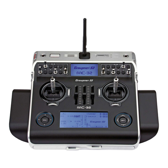
    Description of the transmitter Control elements on the transmitter Knob control (depressible): left "DG4", right "DG2" Connection sockets (protected by a cover) Control sticks (2 sticks for a total of four independent control functions) Roller control Speaker Antenna with folding and swivel joint LCD (telemetry indicators, standard receiver parameters) ON/OFF switch and LED indicators (battery, RF radiation, warning signals) Option locations (for retrofitting the transmitter with switches and knob modules 8 switches included as...
  • Page 13: Transmitter Interior

    Transmitter interior 1 3 free plug-in locations and blind connectors (for 3 proportional rotary control modules) for optional controls and switches (connection sequence as preferred) 2 INT PPM plug-in location (one free plug-in location for connecting an additional – internal – RF module) 3 Transmitter battery 4 Transmitter battery plug 5 Plug-in locations (6 free plug-in locations for additional switches are standard, these switch plug-in...
  • Page 14: Interfaces

    Interfaces Face-side connections Left face-side connections 1- Card slot The card slot is suitable for micro SD memory card. For informa- tion on removing and inserting the memory card, refer to the section "memory cards". 2- Ear phones port The ear phones port is suitable for a 3,5 mm jack. Though this interface both acoustic signals and voice messages are emitted.
  • Page 15: Dsc Socket

    DSC cable the RF module of the transmitter remains inactive. The status LED is constantly red and in the display will appear DSC. In the mc-32 HoTT transmitter upper display appears the trans- mitter logo. The transmitter is now ready for use.
  • Page 16: Memory Cards

    This type of connection should therefore only be used if you protect yourself from electrostatic discharge while operating the simulator by wearing a commercially available grounding armband. Graupner therefore strongly recommends only using wireless simulators. Memory cards Micro SD cards up to 2 GB and micro SDHC up to 32 GB are compatible memory cards.
  • Page 17: Display And Touchpad

    11 Symbol "micro SD card insert" 12 Transmitter operating time (automatically reset to 00:00 if the voltage is at least 0,3 V higher) 13 Signal power 14 Operating mode 15 Graupner logo or flight phase name 16 Receiver battery voltage RX-VOLT 17 / 36 33032_jp_V1...
  • Page 18: Telemetry Symbols In The Display

    Telemetry symbols in the display The active model memory has not yet been bound to a receiver. Not flashing: RF transmitter function switched off. Blinking antenna symbol: Last receiver bound to the active model memory is inactive or out of reach No telemetry signal to receive Signal strength display of the model connection Signal strength display of the connection with pupil transmitter...
  • Page 19 3. By briefly pressing the keys simultaneously or an altered parameter value for the active entry field will again be restored to its default value (CLEAR). Note In the event the keys do not exhibit any functionality immediately after switching the transmitter off and then on again right away, this is not a fault.
  • Page 20: Commissioning

    Commissioning Opening/closing the transmitter housing The transmitter should be opened only in the following cases:  If a self centering stick has to be converted in non self cen- tering  If a non self centering stick has to be converted in self cen- tering ...
  • Page 21: Brake Spring And Ratchet

    Left turn = return softer Brackets for transmitter belt A stable transmitter hanger for fastening neck straps is standard equipment on the mc-32 HoTT transmitter. Installing the metal brackets: Push both brackets inward a bit near where they are engraved.
  • Page 22: Installation Of Switches, Switch Modules And Knob Modules

    The fixation is made by screwing a nut on the thread on the upper part of the switch. These will pass though the housing and tightened with a suitable wrench. The Graupner trim nut wrench is well suited for tightening down these nuts.
  • Page 23: Binding

    Otherwise the RF module will be activated when the transmitter Please select RF on/off? is switched on and in the display appears a selection indicator. Select with the selection buttons of the right touch pad RF ON/ Please select OFF. By tipping the SET button on "OFF" the RF module is RF on/off? switched off.
  • Page 24  Always connect only one battery to the battery charger out- put.  Use only batteries and battery cables with suitable connec- tors and reverse polarity protection. Make sure that the polarity is correct.  After the charge is complete disconnect the charger from the power source.
  • Page 25: Charge Possibilities

     The battery charger can be used only in dry spaces.  A wet charger, even if re-dried, should no longer be used. Never use a damaged battery charger.  Due to licensing reasons, any reconstruction and/or modifi- cation of the product is prohibited. ...
  • Page 26: Low Voltage Warning

    NOTE The charging socket comes standard with a protection switch that protects against polarity reversal. Original Graupner automatic char- gers recognize the battery charge. In order to prevent damage to the protection switch and to the other components, charging current should never exceed 1 A.
  • Page 27: Use And Menu Functions

    Use and menu functions Short-Cuts The following key combinations can be used to directly call up certain menus and options:  CLEAR Brief simultaneous touch of the keys or on the right touch pad will restore the active entry field's changed parameter value back to its default value.
  • Page 28: Function Field In The Display

    Only the menu points associated with the selected preamble are shown. The description of the single menu point is available in the pro- gramming manual (Manual part 2) on www.graupner.de. Function field in the display Depending on the given menu, certain function fields will appear on the bottom display line.
  • Page 29: Announcements

    On the included micro SD card are already available the follow- ing languages: German, English, French, Dutch, Italian and Spanish, Czech and Russian. The recent language packets are available on www.graupner.de. Language change Language change step by step: Insert the included memory card in its slot as described in the "Memory card"...
  • Page 30: Stick Calibration

    Firmware update step by step: Move with a short pressure on the SET key to the selection page of the option "FIRMWARE UPDATE". Select the firmware version with the selection keys. Confirm by pushing the SET key. The storing in the transmitter memory will start: Firmware Download Boot Download Firmware...
  • Page 31: Bluetooth Initialization

    cyclically select the positions of the four calibrated sticks. Touching the ESC key will terminate the process and return to the sub-menu "Stick cali.". Example: Bring here the respective left blinking selection arrow of the right stick to the left limit. Tip on the SET key. So the cal- ibration of the right stick left limit.
  • Page 32: Receiver

    Lowest operating voltage of the receiver power supply since the last startup in Volts The thermometer visualizes the current operating temperature of the receiver A detailed explication of the values on the left column is available in the Manual Part 2 on www.graupner.de. 32 / 36 33032_jp_V1...
  • Page 33: Firmware Update

    Only operate your transmitter using the current software version.  these information can also be found at: www.graupner.de => Service & Support => Update and revision history for GRAUPNER HoTT components. Before each update, check the transmitter battery charge or ...
  • Page 34: Update Through Usb Port

    The present construction or user manual is for informational pur- poses only and may be changed without prior notice. The cur- rent version can be found on the Internet at www.graupner.de on the relevant product page. In addition, Graupner/SJ has no responsibility or liability for any errors or inaccuracies that may appear in construction or operation manuals.
  • Page 35 35 / 36 33032_jp_V1...

This manual is also suitable for:

33032

Table of Contents