Shure Microflex Wireless User Manual
Hide thumbs
Also See for Microflex Wireless:
- Quick start manual (78 pages) ,
- Interfacing and programming manual (5 pages) ,
- Manual (73 pages)

Subscribe to Our Youtube Channel
Related Manuals for Shure Microflex Wireless


Summary of Contents for Shure Microflex Wireless
- Page 1 Discussion and Conferencing MICROFLEX WIRELESS ® USER GUIDE ©2016 Shure Incorporated 27WG20831 (Rev. 6)
-
Page 2: Important Safety Instructions
IMPORTANT SAFETY INSTRUCTIONS 14. REFER all servicing to qualified service personnel. Servicing is required when the ap- paratus has been damaged in any way, such as power supply cord or plug is damaged, liquid has been spilled or objects have fallen into the apparatus, the apparatus has been READ these instructions. -
Page 3: Table Of Contents
Advanced Setup General Description Features Software MXW Wireless System System Design and Technology Shure Web Device Discovery Application MXW System Control Software Hardware Description Control Software for the MXW Audio Network Interface Dante Software by Audinate Access Point Transceiver (APT) ®... -
Page 4: Overview
Overview Overview ■ General Description ■ Features Legendary Shure Quality Advanced Networking and Control ■ MXW Wireless System Components of the MXW System ■ System Design and Technology Technology Overview of the Audio Path Forming Groups and Linking Microphones Configurations: Managing Multiple Groups... -
Page 5: General Description
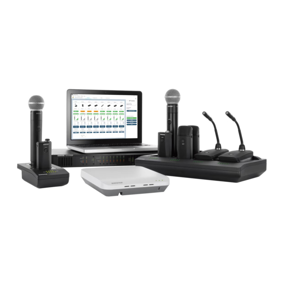
Overview General Description The Shure Microflex Wireless Series (MXW) is a complete microphone solution for flexible meeting rooms and ® boardrooms. It features automatic RF channel management, rechargeable encrypted (AES256) wireless microphones, and digital audio networking (Dante ). The networked charging station charges boundary and gooseneck microphones for tabletop applications, as well as handheld and bodypack solutions for corporate training and presentations. -
Page 6: Features
US Government National Institute of Standards and without removal from the microphone. Lithium-Ion chemistry Technology (NIST) publication FIPS-197. and intelligent Shure circuitry results in a rechargeable battery with no memory effect. Battery statistics are viewable from the control software (battery runtime, time to full charge, charge cycle count and battery capacity). -
Page 7: Mxw Wireless System
Overview MXW Wireless System ① Wireless Microphones ② System processor and wireless transceiver ③ Microphone linking and charging station ④ Analog output device with gigabit network switch ⑤ Shielded Cat5e cables (not included) - Page 8 It features a TQG input for lavalier connection and an integrated omnidirectional microphone. Handheld (MXW2) The handheld enables presenters to communicate using legendary Shure SM58, SM86, BETA58 and VP68 microphone cartridges. Boundary (MXW6/C, MXW6/O) The boundary transmitter sits on a table or desk to transmit...
- Page 9 Overview Networked Charging Station (MXWNCS2, MXWNCS4, MXWNCS8) The Networked Charging Station (2, 4 and 8 slot varieties) is capable of simultaneous charging MXW microphones. It also links microphones to access point channels and networks battery statistics to the control software. Note: The MXWNCS2 does not work with the MXW8 gooseneck microphones.
-
Page 10: System Design And Technology
Overview System Design and Technology Technology Overview of the Audio Path The MXW System combines Shure legendary audio quality • Digital audio is carried over Ethernet cables and standard with advanced digital networking technology. The following IP equipment. is an overview of the audio path: •... - Page 11 Overview Forming Groups and Linking Microphones Once all the MXW components are connected to the Each Group is managed by a single access point. network, they can be associated into Groups from the Microphones are Linked to channels in the access point, Configuration tab of the control software.
-
Page 12: Hardware Description
Hardware Description Hardware Description ■ Access Point Transceiver (APT) Directional Antennas ■ Audio Network Interface (ANI) Front Panel Back Panel ■ Networked Charger (NCS) Connecting Microphones ■ Microphone Transmitters Description Microphone Transmitters ■ Rechargeable Batteries Networked Charging Station (NCS) USB Charger Battery Statistics on Control Software Reset the Microphone Battery Statistics Battery Replacement... -
Page 13: Access Point Transceiver (Apt)
Hardware Description Access Point Transceiver (APT) The access point transceiver is the hub of the audio signal • Sends and receives control information (such as gain flow and manages the RF stability of each microphone in adjustment and link settings) between the components, the group. - Page 14 Hardware Description ⑤ Ethernet Port ⑦ Ethernet Link Speed LED (Amber) Connect a shielded Cat5e (or higher) cable to a PoE source • Off = 10/100 Mbps • On = 1 Gbps (required for proper MXW functionality) and the network. ⑧...
-
Page 15: Audio Network Interface (Ani)
Hardware Description Audio Network Interface (ANI) The ANI performs the following functions: • Front-panel interface provides status indicators and access to basic system controls. • Converts digital audio from the network into analog audio • Hosts an embedded web server that provides an interface to connect to a sound reinforcement system or recording for monitoring and control of the device. - Page 16 Hardware Description ⑨ Output Attenuation Control ⑫ Headphone Volume Knob Use the up/down buttons to attenuate the channel output Adjusts the volume to the headphone output. from 0 dB (no attenuation) to -24 dB in 1 dB increments, and from -24 to -78 in 3 dB increments. ⑬...
- Page 17 ④ Chassis Ground (1-8) Provides Power over Ethernet (PoE) for Port 1 Use to directly ground the cable shield to the chassis. the Shure access point and functions as a (PoE) standard gigabit port. ⑤ Input Block Connectors (A,B) Standard gigabit ports enable the connection...
-
Page 18: Networked Charger (Ncs)
Hardware Description Networked Charger (NCS) Model Variations The MXW networked charging station enables battery charging and channel linking from a single location. When • Accepts eight boundary, bodypack, or a charger is associated to a group, its channel slots are MXWNCS8 handheld microphones mapped to access point audio channels. - Page 19 Hardware Description ⑥ Locking DC Power Supply ⑨ Ethernet Status LED (Green) Secures the PS45 power supply to the input jack of the • Off = no network link. • On = network link established. station. • Flashing = network link active. ⑦...
-
Page 20: Microphone Transmitters
Hardware Description Microphone Transmitters ⑧ ⑦ ⑩ ⑨ ③ ③ ① ④ ⑥ ⑤ ② ⑥ ③ ② ⑤ ① ③ ② ④ ② ① ⑤ ① ⑥ ⑥ MXW8 MXW6 MXW1 MXW2 Description ① Power Button ④ Low Battery LED (Gooseneck and Boundary only) MXW6, MXW8: Press and hold the dedicated power button Color Status... - Page 21 Hardware Description ⑧ TQG Connector Status Description The MXW hybrid bodypack has a TQG connector for an external lavalier or headset microphone. Out of RF The transmitter is out of the Pulsing Coverage RF coverage range to the (short on/ ⑩...
- Page 22 Hardware Description Microphone Transmitters MXW microphones transmit an encrypted, wireless audio signal to the access point. Four form factors are available: Hybrid Bodypack (MXW1) The bodypack secures to a belt or strap for hands-free, mobile communication. It features a TQG input for lavalier microphone connection and an integrated omnidirectional microphone.
- Page 23 Hardware Description Handheld (MXW2) The handheld enables presenters to communicate using legendary Shure SM58, SM86, BETA58 and VP68 microphone cartridges. MXW1 MXW6 MXW2 Correct Microphone Placement • Hold the microphone within 12 inches from the sound source. For a warmer sound with increased bass presence, move the microphone closer.
- Page 24 Hardware Description Boundary (MXW6/C, MXW6/O) The boundary transmitter sits on a table or desk to transmit speech while discreetly blending into any conference environment. Cardioid and omnidirectional versions are available. Microphone Placement For best low-frequency response and rejection of background noise, place the microphone on a large, flat surface, such as MXW1 MXW6 MXW2...
- Page 25 Hardware Description Desktop Gooseneck Base (MXW8) The gooseneck base is compatible with 5, 10, and 15” Microflex gooseneck microphones. MXW1 MXW6 MXW8 MXW2 2.5 cm (1 in) Microphone Types Insert Microphone into Base MX405R, MX410R & MX415R Light Ring MX405, MX410 & MX415 Bi-color Status Indicator...
-
Page 26: Rechargeable Batteries
Hardware Description Rechargeable Batteries MXW lithium-ion rechargeable batteries use advanced chemistry that maximizes transmitter runtime with zero-memory effect. Power management from the control software provides detailed visibility to critical battery parameters such as charge status, battery capacity, and cycle count. Batteries can be charged to 50% capacity in one hour and to full capacity in two hours using the MXW Networked Charging Station. - Page 27 Hardware Description Charge Status LEDs Each charger channel has a row of LEDs that illuminate to indicate the microphone battery charge level: % Battery Charge • Flashing: <10% • Solid: >10% >25% >50% >75% >95% NCS Energy Efficient Mode Operate the charger in a low-energy mode to reduce power consumption. In this mode, only one LED indicator illuminates per channel after powering on.
- Page 28 Hardware Description Battery Statistics on Control Software The MXW control software is used to manage battery information. Use the Monitor tab to view battery charging status: Monitoring Battery Charge Status In the Charging Station: Displays the remaining time until the microphone battery is fully charged. During Use: Displays the remaining battery runtime of the microphone.
- Page 29 Battery Replacement Lithium Ion Batteries have no “memory effect”, and instead experience a more linear reduction in capacity. Shure recommends establishing a battery replacement schedule customized to the client requirements and replacing batteries when the capacity is no longer acceptable.
-
Page 30: Installation
Installation Installation ■ Additional Equipment ■ Rack Installation ■ Securing the Charging Station ■ Two-Channel Charger Wall Mount Installation NCS2 Mount Dimensions ■ Mount the Access Point Transceiver Select a Location Securing to a Wall or Ceiling External Cover for Painting ■... -
Page 31: Additional Equipment
Installation Additional Equipment Network Cables Use shielded Cat5e (or higher) Ethernet cables, limiting cable runs to 100 meters maximum between network devices. Audio Cables Reference the hardware kit user guide supplied with the MXW Audio Network Interface to assemble audio cables to the connectors. -
Page 32: Rack Installation
Installation Rack Installation Rackmount the device using the screws and washers supplied in the Hardware Kit. Follow these general best practices when installing equipment in a rack: • Ambient temperature of the rack should not exceed specified operating temperature range of the device. •... -
Page 33: Securing The Charging Station
Installation Securing the Charging Station This kit provides washers and screws for securing a charging tray to a table or other surface. Use two kits for the NCS8. Please refer to the NCS mounting template for screw hole placement. Important: The top of the screw must extend exactly ⁹/₆₄ (0.149) inches (3.78 mm) above the surface (about 4½ threads). - Page 34 Installation >40 mm [1.57”] Leave space behind the charger for cabling 36.6 mm [1.441”] NCS8 126.6 mm [4.984”] 51.4 mm [2.025”] 141.4 mm [5.568”] 201.4 mm [7.931”] 291.4 mm [11.474”] >40 mm [1.57”] >40 mm [1.57”] 36.6 mm 21.8 mm [1.441”] [0.858”] NCS4...
-
Page 35: Two-Channel Charger Wall Mount
Installation Two-Channel Charger Wall Mount The two-channel charger includes a wall-mount to provide quick microphone access and storage in a classroom or conference room. NCS2 Secures to a Classroom Wall Tip: Paint the mount to match the wall for a less obtrusive installation. -
Page 36: Installation
Installation Installation 1. Determine the orientation and placement of the mount. Placement Orientation Wall Drawer or tray 2. Leave room around the mount for cabling to the charging station. >40 mm [1.57”]... - Page 37 Installation 3. Attach the mount to the wall. Use one set of screw holes depending on the orientation of the mount. Drawer installation Wall installation Mount Screw Holes 4. Align the charger on the mount and secure with the screws. Tip: Improve cable management using the cable tie holes on the mount.
-
Page 38: Ncs2 Mount Dimensions
Installation NCS2 Mount Dimensions 95 mm [3.740”] 35 mm 60 mm [1.378”] [2.362”] 95 mm [3.740”] 35 mm 60 mm [1.378”] [2.362”] 16 mm [0.630”] 16 mm 46 mm [0.630”] [1.811”] 46 mm [1.811”] 95 mm [3.740”] 35 mm 60 mm [1.378”] [2.362”] 16 mm... -
Page 39: Mount The Access Point Transceiver
Installation Mount the Access Point Transceiver The directional antennas of the APT send and receive the RF signal in a cardioid pattern with the greatest sensitivity toward the face of the device. Always aim this side toward the microphone coverage area. Select a Location The access point is typically mounted to a ceiling or wall Important: Always perform a "walk around"... -
Page 40: Securing To A Wall Or Ceiling
Installation Securing to a Wall or Ceiling Required Equipment • Two #8 screws at appropriate length* *Screw Length = Surface thickness + thread engagement (4.75 mm max.) + thickness of flat washer + the thickness of the split lock washer Installation Steps 1. -
Page 41: Power The Hardware
Installation Power the Hardware ① Audio Network Interface (ANI) Connect the IEC power cable from the back panel to an AC power source. Turn on the power switch. ② Access Point Transceiver (APT) Connect a shielded Cat5e cable from the MXWAPT to network Port 1 of the MXWANI. If using an external gigabit switch, ensure Class 0 PoE provides at least 6.5W of power to the APT. -
Page 42: Fully Charge The Transmitters
Installation Fully Charge the Transmitters Whenever possible, charge to full the MXW transmitters before an event. Transmitters can be charged in any networked charging station, even if it is associated to another Group or on a separate network. Battery Charge Times Approximate Charge Times Charger Type Time to Full Charge* (hr:min) -
Page 43: Connect The Components
To Component Access Point Transceiver ① Port 1 (PoE) (APT) Networked Charging ② Port 2 Station (NCS) ③ Port 3 (Optional) Additional NCS ④ Port 4* Computer *When Port 4 is set to Uplink mode, Shure Discovery Application support is restricted. -
Page 44: Multiple Group System (>1 Access Point)
Installation Multiple Group System (>1 Access Point) When an installation requires more than eight channels, additional MXW components can be connected to expand the system. A gigabit router is required to connect all components to the same network. The following are several topologies for multiple group systems. -
Page 45: Accessing The Mxw Control Software
Turn off the PC's WiFi to force the wired network interface. 4. Launch the Shure Web Device Discovery application. Open the application to view all Shure devices on the network that feature an embedded server for control software (MXWAPT, MXWANI and SCM820). Use the Identify button to flash a device's LEDs for easy identification. -
Page 46: System Setup
System Setup System Setup ■ Group Devices to Form Audio Channels Select Devices for the Group Lock the Configuration Automatic Group Setup ■ Channel Routing between Devices Charging Station Examples Audio Output Examples ■ Link Microphones to Group Channels ■ Preparing a Backup Microphone One Active Mic per Channel Procedure ■... -
Page 47: Group Devices To Form Audio Channels
System Setup Group Devices to Form Audio Channels Use the group configuration to form the audio channel between the microphone, the access point (APT), charger and audio output device. The audio channel establishes the audio routing, RF coordination, and data control for a set of devices. -
Page 48: Select Devices For The Group
Select one or two audio output devices (MXWANI or SCM820) to automatically route the digital audio channels from the access point. Select from the following devices: • Audio Network Interface (MXWANI) four- or eight-channel variation. • Shure SCM820 IntelliMix Mixer. Dante-enabled SCM820s can be selected as the audio output for the Group. This automatically ®... -
Page 49: Lock The Configuration
System Setup Lock the Configuration Repeat steps 1-4 for additional groups in the configuration. All groups in a configuration share the same preferences and global microphone actions. Up to 10 groups are available per configuration. When finished with the configuration setup, select the Lock Configuration button to improve network performance and system stability. -
Page 50: Automatic Group Setup
System Setup Automatic Group Setup An MXW Group can be associated without use of the control software when a network is comprised of only one Access Point Transceiver (APT), one Networked Charging Station (NCS) and one Audio Network Interface (ANI). For best results, perform a factory default on the devices to clear any previous Group associations. -
Page 51: Channel Routing Between Devices
System Setup Channel Routing between Devices Channels are routed when charging stations and output devices are selected to fill the APT group (2-, 4-, or 8-channels). Once the devices are selected for the group, the channels are mapped between the charging slots, audio outputs and the wireless receiver. -
Page 52: Charging Station Examples
NCS A NCS B System Setup 2 3 4 5 6 7 8 Charging Station Examples NCS A NCS B 8-Channel Group 4-Channel Group NCS A NCS B 2 3 4 6 7 8 NCS A NCS B x x x x x x x x NCS A NCS B... -
Page 53: Audio Output Examples
System Setup Audio Output Examples 8-Channel Group Out A Out B Out A Out B Out A Out B HEADPHONE 1 2 3 4 5 6 7 8 HEADPHONE 1 2 3 4 5 6 7 8 push to solo | hold to mute push to solo | hold to mute HEADPHONE 1 2 3 4 5 6 7 8... -
Page 54: Link Microphones To Group Channels
System Setup Link Microphones to Group Channels • Control Software: From the Configuration page, press the Use the Networked Charging Station (NCS) to Link Link button for each charger in the Group. microphones to Access Point channels. Slots in the charger •... -
Page 55: Preparing A Backup Microphone
System Setup Preparing a Backup Microphone Prepare an alternate microphone for each channel for more reliable and flexible events. Two MXW microphone transmitters can be linked to the same channel, providing the option of either microphone for use. The administrator can designate the secondary mic to anticipate needs that may arise during events: Handheld Bodypack Microphone Preference... -
Page 56: One Active Mic Per Channel
System Setup One Active Mic per Channel Only one microphone will operate on the channel at a time, blocking the second microphone from interfering with the RF and audio performance. The backup microphone briefly flashes the LED to indicate the channel is occupied, and automatically turns off to conserve the battery. -
Page 57: Configurations: Managing Multiple Groups
"Are You Sure?". If Yes is system operations across multiple devices. selected, the browser will close and a new Configuration Master is automatically selected. Use the Shure Discovery Application to re-open the control interface from any remaining MXW Access Point. -
Page 58: Device Availability
System Setup Device Availability Associated Device When setting up a group or managing devices, it is important to understand the difference between open and A device is considered 'associated' once it has been associated devices. selected in a group row. Each device can only belong to one group at a time (and therefore one Configuration). -
Page 59: Exchanging Or Removing A Component
System Setup Exchanging or Removing a Component Exchanging a Transmitter Important: Use caution when replacing microphones, The same Link procedure is done to exchange a transmitter in a group. Place the new transmitter in the charger slot as the Link procedure applies for all microphones in that corresponds to the desired channel and perform the the charger. -
Page 60: Link A Microphone Over The Network
Group settings are not *A comprehensive list of MXW command strings are affected by this procedure. available on the Shure website: http://shure.custhelp. com/app/answers/detail/a_id/5207 1. Connect a spare charger to the network. 2. Place the microphone in a charging slot. -
Page 61: Wireless Management
Wireless Management Wireless Management ■ Overview of Channel Coordination Maximum Channel Count ■ Scanning Available RF Spectrum Performing a Scan ■ Setting RF Power ■ Using Multiple 2- or 4-Channel Access Points Requirements Set Up... -
Page 62: Overview Of Channel Coordination
Wireless Management Overview of Channel Coordination The MXW system operates using time division multiple point, which manages the spectrum and seamlessly access (TDMA) to carry MXW channels (audio and changes slots if interference is detected. The MXW system control data) within defined RF spectrum. Channels are makes this adjustment automatically and without audio automatically assigned to the time-slots by the access artifacts. -
Page 63: Scanning Available Rf Spectrum
Wireless Management Scanning Available RF Spectrum The MXW Wireless components operate in unlicensed Radio Frequency Interference (RFI) spectrum that is shared with other wireless devices The scanner analyzes the spectrum and divides the data operating in the same area, such as cordless phones, into three categories: walkie-talkies and intercoms. - Page 64 Wireless Management Performing a Scan Follow these steps to perform RF scan. 6. Press the Spectrum Scanner button. The Spectrum Scan window opens. Tip: Perform the scan during typical hours of 7. Press the Start Scan button at the top of the window. If operation to best capture the typical interference in any microphones are Linked to that Access Point, they an environment.
-
Page 65: Setting Rf Power
Wireless Management Setting RF Power The RF radius of a configuration can be limited to allow another MXW system to re-use the frequency time-slots. It is best practice to use the lowest setting that supports the installation. Perform a walk-around test with the transmitters to ensure that the coverage setting is sufficient. -
Page 66: Using Multiple 2- Or 4-Channel Access Points
Wireless Management Using Multiple 2- or 4-Channel Access Points The MXW access point uses two sets of antennas to cover the operating spectrum. Each antenna set covers half of the timeslots used for MXW channels. Eight-channel units use both antenna sets simultaneously; two- and four- Mode A channel units use one set at a time, operating on half of the available timeslots. - Page 67 Wireless Management Set Up 1. Open the MXW control software using the Shure Web 5. Open the Device Properties for the adjacent APT2 or Device Discovery application. APT4. 2. Go to the Utility page. 6. Set the unit to Mode B (Device Propterties >...
-
Page 68: Networking
■ Configuring IP Settings Manually Assigning Static IP Address ■ Advanced Setup Managing Large Systems on a Single Network Network Audio and Shure Control Data Isolating Audio and Control Networks Operating the Control Software over Wi-Fi Dedicate a Device for Master Clock... -
Page 69: Networking Best Practices
The MXW control software coordinates IP updates across the entire system of devices. To configure the IP properties, follow these steps: 1. Open the MXW control software from the Shure Web Device Discovery app. 2. Go to the Utility tab. - Page 70 8. Change the computer's IP address to match the subnet 3. Select the Manual (Static) IP Mode. of the MXW equipment. 4. Enter the IP settings 9. Reopen the MXW control interface using the Shure 5. Select the Add Updates button to queue the saved Device Discovery application. settings.
-
Page 71: Advanced Setup
Uplink mode to dedicate one of its network ports as a control network. This protects the audio from distributing control-only connection. Uplink mode blocks multicast traffic to the entire network and significantly decreases network from Port 4 of the ANI, restricting network audio and Shure traffic. Discovery data. - Page 72 Networking Because the device will not show up in the Shure Device 3. Use the Shure Web Device Discovery application to Discovery application, the IP address of the control open the control software of the ANI. software must be recorded to access the server.
-
Page 73: Software
Software Software ■ Shure Web Device Discovery Application ■ MXW System Control Software Log On Page Control Bar Monitor Tab Configuration Tab Link Microphones Utility Tab Preferences Tab ■ Control Software for the MXW Audio Network Interface Log On Page... -
Page 74: Shure Web Device Discovery Application
Software Shure Web Device Discovery Application The Shure Web Device Discovery application is used to 9. Device List: List of Shure devices with an embedded access the graphical user interface (GUI) of a Shure device. GUI on the same network. -
Page 75: Mxw System Control Software
• Configuration: Form groups of components ④ Shure Link • Utility: View details and manage IP settings of each MXW device on the network Links to the Shure website at www.shure.com. • Preferences: Assign microphone and system behavior ⑤ Language Selection ② Security Level Selects the language for the control software interface. - Page 76 Software Monitor Tab ① Access Point Selection • Standby: On but in a 'sleep' state with audio muted. Standby conserves battery charge and enables a change to the Determines which Access Point is displayed on the tab. microphone's status from the control software. •...
- Page 77 Software ⑫ High-Pass Filter • Link: Links the microphone from the corresponding charging slot. Engages a 12 dB-per-octave filter below 150 Hz for • Unlink: Unlinks the microphone from the audio channel. attenuating undesired low frequencies, sometimes caused by table vibrations or air-conditioning rumble. ⑯...
- Page 78 Software Link Microphones Up to two microphones can link to each audio channel, ② Link Button though only one is on air at-a-time. Use the secondary link Links microphones in the charger to audio channels. slot to add a microphone for battery redundancy or flexibility during events.
- Page 79 Displays the IP Address of the control network interface Un-check the filter to view all MXW devices on the subnet. (Shure control data). Note: The filter is checked when the configuration is locked from the ⑧ IP Address Network Audio Configuration tab.
- Page 80 Some settings vary depending on the device capabilities. See the Networking section for configuring each MXW device. • Control: Shure control (software interface operation, firmware updates, Shure Device Discovery application). • Network Audio: Dante network audio (digital audio networking and Dante software).
- Page 81 Software Preferences Tab All preferences apply to each device in the Configuration. ④ Mute Preference • Local Mute - Individual (default): Each transmitter is muted ① Switch Behavior individually. • Local Mute - All: All transmitters mute when any transmitter Customize the switch on each transmitter type.
- Page 82 • Disabled: Flashing LEDs only (no sound) ⑭ Register the Product Link ⑪ Language Links to Shure website for product registration. Determines the language of the control software. ⑫ Password Setup The default password for the device is 'admin'. The following describes access rights for each logon: Admin (default): Full monitoring and editing access.
-
Page 83: Control Software For The Mxw Audio Network Interface
Software Control Software for the MXW Audio Network Interface The MXW Audio Network Interface features a control software to mange the analog inputs and outputs of the MXW system, in addition to the 4-port gigabit switch on the back panel of the network interface. By default, all MXW devices have the password 'admin' applied to the control software. - Page 84 Software Control Bar ② ③ ④ ⑤ ① ① Tabs ④ Log Off The software has an Inputs/Outputs tab for managing audio Logs the user out of the software. and a Preferences tab for system configurations. ⑤ Language Selection ② Identify Button Selects the language for the control software interface.
- Page 85 • Switched Mode (default): Full Ethernet support on port 4. Reboots the device with factory default settings. • Uplink Mode: Only control data is transported. Multicast traffic for Dante digital audio and the Shure Web Device ⑤ Register This Product Link Discovery application is restricted.
-
Page 86: Dante ® Software By Audinate
Software Dante Software by Audinate ® Audinate software provides additional function and control of the Dante digital audio network. Visit Audinate's website ® for instructions for download and installation. Dante Controller Dante Controller (DC) is free software by Audinate that is Note: DC software is not required for routing audio used to configure and manage a network of Dante devices. -
Page 87: Firmware Updates
Firmware Release Requirements Microflex Wireless devices comprise a network with multiple communications protocols that work together to ensure proper operation. The recommended best practice is that all MXW devices are on an identical release. To view the firmware of each MXW device on the network, open the Utility page of the MXW control software. -
Page 88: Troubleshooting
Troubleshooting Troubleshooting ■ Troubleshooting ■ Additional Resources ■ Factory Reset From the Hardware From the Control Software ■ Connecting to an External Control System ■ IP Ports and Protocols... -
Page 89: Troubleshooting
Troubleshooting Troubleshooting The following table offers typical solutions when troubleshooting the Microflex Wireless System. Audio Problem Indicator Solution • Check cables • Check that transmitters are on and channels are un-muted • Check that the input meters are OK on the Monitor tab of the MXW control software. -
Page 90: Additional Resources
Additional Resources For additional Troubleshooting assistance or further information on complex installations, contact Shure to speak with a support representative. In the Americas region, call Systems Support group at 847-600-8440. For users in other locations, go to www.shure.com to find support contact for your region. -
Page 91: Factory Reset
Factory software will reset to admin. default settings are designed for automatic compatibility with other Shure networked devices. From the Hardware Access Point Transceiver Press and hold the recessed reset button for 10 seconds. -
Page 92: Connecting To An External Control System
The MXW System connects to an AMX or Crestron control system via the Ethernet. Use only one controller per system to avoid messaging conflicts. For a comprehensive list of MXW command strings, visit: http://shure.custhelp.com/ app/answers/detail/a_id/5207 • Connection: Ethernet (TCP/IP; MXW is the client) -
Page 93: Ip Ports And Protocols
8181* Flash Required for web web application Open 8427 Multcast SLP Required for inter-device communication Open † 64000 Telnet Required for Shure firmware update Open Dante Audio & Controller Port TCP/UDP Protocol Description SNMP Used by Dante [319-320]* Dante clocking †... -
Page 94: Accessories And Model Variations
Accessories and Model Variations Accessories and Model Variations MXW Device Description Part Number 8-Channel Access Point Transceiver MXWAPT8 4-Channel Access Point Transceiver MXWAPT4 Access Point Transceiver 2-Channel Access Point Transceiver MXWAPT2 Mounting Plate 65A20096 Paintable Cover 65A20030 8-Channel Audio Network Interface MXWANI8 4-Channel Audio Network Interface MXWANI4... - Page 95 Accessories and Model Variations Lavalier Options Microphone Description Part Number Microflex 5mm Subminiature Lavalier, Omnidirectional, Black MX150B/O-TQG ® Microflex 5mm Subminiature Lavalier, Cardioid, Black MX150B/C-TQG ® Microflex Omnidirectional Subminiature Earset, Black MX153B/O-TQG ® Microflex Omnidirectional Subminiature Earset, Tan MX153T/O-TQG ® Microflex Omnidirectional Subminiature Earset, Cocoa MX153C/O-TQG...
-
Page 96: Microflex Wireless Specifications
Microflex Wireless Specifications Microflex Wireless Specifications ■ System ■ Transmitters MXW1 Hybrid Bodypack Transmitter MXW2 Handheld Transmitter MXW6 Boundary Transmitter MXW8 Gooseneck-Base Transmitter ■ Access Point Transceiver (APT) ■ Networked Charging Station (NCS) ■ Audio Network Interface (ANI) Analog Connections... -
Page 97: System
Microflex Wireless Specifications System System Audio Polarity RF Carrier Frequency Range Positive pressure on microphone diaphragm (or positive Band Region Frequency Range voltage on pin 3 of TA4M connector) produces a positive USA, Canada, Mexico 1920–1930 MHz voltage on pin 2 of the ANI (with respect to pin 3 of the low-impedance output). -
Page 98: Transmitters
Microflex Wireless Specifications Transmitters Gain Adjustment Range Battery Type −25 to +15 dB (in 1 dB steps) Rechargeable Li-Ion Maximum Input Level Battery Life Mic gain @ −16 dB MXW1, MXW6, MXW8 Up to 9 hours −9 dBV MXW2 Up to 15 hours Calculated with a new battery. -
Page 99: Access Point Transceiver (Apt)
108 g (3.8 oz.) with batteries MXW8 Gooseneck-Base Transmitter Microphone Connector Gooseneck Options 6-pin connector for Shure MX405/10/15 See accessories list Configuration Dimensions Unbalanced 36 mm x 71 mm x 124 mm (1.4 in. x 2.8 in. x 4.9 in.) H x... -
Page 100: Networked Charging Station (Ncs)
Microflex Wireless Specifications Networked Charging Station (NCS) Charge Time NCS2 48 mm x 102 mm x 154 mm (1.9 in. x 4.0 in. x MXW1, MXW6, MXW8 50%=1 hour; 6.1 in.), H x W x D 100%=2 hours Weight MXW2 50%=1.5 hour;... -
Page 101: Audio Network Interface (Ani)
Microflex Wireless Specifications Audio Network Interface (ANI) Audio Frequency Response Dimensions 20 Hz to 20 kHz (+1, −1.5 dB) 44 mm x 483 mm x 366 mm (1.7 in. x 19.0 in. x 14.4 in.), H x W x D... -
Page 102: Digital Signal Processing
Microflex Wireless Specifications Digital Signal Processing AD/DA Converter Dante-to- 0.24 ms + TN Analog 24-bit, 48 kHz TN = Network latency in milliseconds, as set in Dante Latency Controller. Estimated Nominal, ±0.1 ms Note: Dante network latency is typically associated with the Analog-to- 0.21 ms... -
Page 103: Transmitter Output Power
Microflex Wireless Specifications Transmitter Output Power Bands: Z10, Z11, Z13, Z15 MXW1 MXW6, MXW8 Setting Setting Medium Medium High High Maximum Maximum MXW2 Setting Medium High Maximum Band: Z12 MXW1, MXW6, MXW8 Setting Medium High Maximum MXW2 Setting Medium High... -
Page 104: Wiring Diagram
Microflex Wireless Specifications Wiring Diagram TA4M Connector Top view of bodypack 5 V DC Ground 5 V DC Active Load Audio Input Audio Input Active Load Ground Audio Network Interface (ANI) Line Audio Input Line +4 dBu = -18 dBFS Signal Select Audio Output... -
Page 105: Safety Information
• Batteries (battery pack or batteries installed) shall not be exposed to excessive heat such as sunshine, fire or the like WARNING: Danger of explosion if battery incorrectly replaced. Operate only with Shure compatible batteries. Note: Use only with the included power supply or a Shure-approved equivalent. -
Page 106: Important Product Information
EMC conformance testing is based on the use of supplied and recommended cable types. The use of other cable types may degrade EMC performance. Changes or modifications not expressly approved by Shure Incorporated could void your authority to operate this equipment. -
Page 107: Certifications
(2) this device must accept The CE Declaration of Conformity can be obtained from any interference, including interference that may cause Shure Incorporated or any of its European representatives. undesired operation of the device. For contact information please visit www.shure.com Le présent appareil est conforme aux CNR d'Industrie...
Need help?
Do you have a question about the Microflex Wireless and is the answer not in the manual?
Questions and answers