
Related Manuals for Shure Microflex MXW


Summary of Contents for Shure Microflex MXW
- Page 1 ® Microflex Wireless Shure Microflex Wireless (MXW) online user guide with specifications and how to set up, install, network, and troubleshoot. Version: 7.4 (2023-A)
-
Page 2: Table Of Contents
Transmitters Exchanging or Removing a Component Access Point Transceiver (APT) Link a Microphone Over the Network Networked Charging Station (NCS) Audio Network Interface (ANI) Large Installations Transmitter Output Power Shure SystemOn Software For Managing Large Systems 5 Wiring Diagram 2/100... - Page 3 Shure Incorporated Safety Information Important Product Information SAFETY PRECAUTIONS Information to the user WARNING Certifications WARNING Trademarks IMPORTANT SAFETY INSTRUCTIONS 3/100...
-
Page 4: Mxw Microflex® Wireless
Microflex Wireless Overview General Description The Shure Microflex Wireless Series (MXW) is a complete microphone solution for flexible meeting rooms and boardrooms. It features automatic RF channel management, rechargeable wireless microphones with encryption (AES256), and digital audio ™ networking using Dante . -
Page 5: Features
Shure Incorporated Features Legendary Shure Quality All Microflex microphones are engineered to clearly capture the natural characteristics of ® Premium Audio voice communications, and include CommShield Technology which guards against unwant ed radio interference from consumer wireless devices such as cell phones and tablets. -
Page 6: Mxw Wireless System
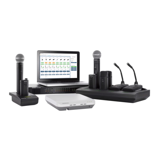
Shure Incorporated MXW Wireless System ① Wireless Microphones ② System processor and wireless transceiver ③ Microphone linking and charging station ④ Analog output device with gigabit network switch ⑤ Shielded Cat5e cables (not included) Components of the MXW System Microphone Transmitters MXW microphones transmit an encrypted, wireless audio signal to the access point. - Page 7 Shure Incorporated Access Point Transceiver (MXWAPT2, MXWAPT4, MXWAPT8) The Access Point Transceiver (2, 4 and 8 channel units) mounts to a wall or ceiling to manage encrypted, wireless audio con nections with microphones. As a system hub, it transports digital audio between the wireless microphones and other Dante de vices on the same network. Audio Network Interface (MXWANI4, MXWANI8) The Audio Network Interface (4 and 8 channel) is a Dante network device that provides analog audio input and outputs for the MXW system. It has a 4-port Gigabit Ethernet switch that enables the connection of an MXW access point, a computer and up to two MXW networked charging stations.
- Page 8 The MXW control software offers comprehensive remote control of key setup, monitoring and management functions. System Design and Technology Technology Overview of the Audio Path The MXW System combines Shure legendary audio quality with advanced digital networking technology. The following is an overview of the audio path: Wireless Audio The MXW transmitter converts speech into a digital signal that is transmitted wirelessly to the access point.
- Page 9 Groups. A Firmware Update May be Required Shure periodically updates device firmware to add features and improve system performance. All devices in your system must operate the same firmware version for full functionality. If your system is not functioning properly, download the appropriate application from the Shure website (https:// www.shure.com/firmware) and update your devices to the latest firmware version. If you require further assistance, please con...
-
Page 10: Hardware Description
Shure Incorporated Hardware Description Audio Network Interface (ANI) Front Panel ① Input Channels Adds analog line- or aux-level signals to the digital network. When the device is associated to an MXW Group, inputs are automatically routed to Linked microphone channels (Input A to channels 1-4; Input B to 5-8). - Page 11 Shure Incorporated ⑦ Input Level Selector Set the selected channel to line- or aux-level to match the input signal. ⑧ Output Level Selector Set the selected channel to an output level that matches the connecting device: ◦ line: +4 dBu ◦...
- Page 12 Four-port gigabit switch for connecting components together for a single MXW Group, or for connecting multiple devices to a larger digital audio network. The following is a description of each port: Port Description Provides Power over Ethernet (PoE) for the Shure access point and functions as a standard gigabit Port 1 (PoE) port. 12/100...
-
Page 13: Access Point Transceiver (Apt)
Normal mode (default): this port functions the same as ports 2 and 3. Port 4 (Uplink) Uplink Mode: only transports control data. This mode blocks network audio and data for Shure Web Discovery Application, Dante Controller and Dante Virtual Soundcard. - Page 14 Shure Incorporated Color Status One or more connected receive channels experiencing a subscription error or is unresolved (trans mitting device is off, disconnected, renamed or has incorrect network setting). Receiving an Identification signal from the control software (simultaneous flash with Link Status Flashing Green LED). The device is performing a spectrum scan (alternating flash with Link Status LED).
-
Page 15: Networked Charger (Ncs)
Shure Incorporated Directional Antennas The access point contains multiple directional antennas to provide steady, reliable wireless communication with the micro phones. It sends and receives the RF signal in a cardioid pattern with the greatest sensitivity toward the face of the device. Al ways aim this side toward the microphone coverage area. Cardioid RF Pattern Networked Charger (NCS) The MXW networked charging station enables battery charging and channel linking from a single location. When a charger is associated to a group, its channel slots are mapped to access point audio channels. - Page 16 Shure Incorporated ① Charging Slots (USB 3.0 Type A) Recharge and link microphones by connecting them to the USB slots on the charger. When the charger is associated to a group, the slots are mapped to access point channels (See Audio Channel Assignment for details).
-
Page 17: Microphone Transmitters
Shure Incorporated ⑨ Ethernet Status LED (Green) ◦ Off = no network link. ◦ On = network link established. ◦ Flashing = network link active. ⑩ Ethernet Link Speed LED (Amber) ◦ Off = 10 Mbps ◦ On = 100 Mbps Connecting Microphones Place a microphone in the charger by connecting it to one of the channel slots. - Page 18 Shure Incorporated ④ Low Battery LED (Gooseneck and Boundary only) Color Status >5% battery runtime remains Solid Red <5% battery runtime remains ⑤ Earphone Jack 1/8" (3.5 mm) jack for monitoring a return channel signal, such as translated audio. This audio is automatically routed from the input(s) of the Audio Network Interface (Input A to channels 1 - 4;...
- Page 19 Shure Incorporated Status Description Charging The transmitter is charging. Battery Statistics Reset Flashing Yellow Battery statistics have been reset for the transmitter. Two microphones trying Red Pulsing (long to connect to same audio Only one microphone for each audio channel can be active at a time.
- Page 20 Shure Incorporated Correct Microphone Placement • Hold the microphone within 12 inches from the sound source. For a warmer sound with increased bass presence, move the microphone closer. • Do not cover grille with hand. Boundary (MXW6/C, MXW6/O) The boundary transmitter sits on a table or desk to transmit speech while discreetly blending into any conference environment. Cardioid and omnidirectional versions are available.
- Page 21 Shure Incorporated To reduce reverberance, avoid reflective surfaces above or to the side of the microphone, such as beveled sides of pulpits or overhanging shelves. Desktop Gooseneck Base (MXW8) The gooseneck base is compatible with 5, 10, and 15” Microflex gooseneck microphones. Microphone Types Insert Microphone into Base 21/100...
-
Page 22: Rechargeable Batteries
Shure Incorporated MX405, MX410 & MX415 Bi-color Status Indicator MX405R, MX410R & MX415R Light Ring MX410DF, MX415DF Dualflex Rechargeable Batteries MXW lithium-ion rechargeable batteries use advanced chemistry that maximizes transmitter runtime. Power management from the control software provides detailed visibility to critical battery parameters such as charge status, battery capacity, and cycle count. - Page 23 Shure Incorporated Models Microphone Type Battery Model MXW1 bodypack MXW6 boundary SB901A MXW8 gooseneck base SB902 MXW2 handheld SB905* * For MXW2 built after 12/2020 Networked Charging Station (NCS) Slide the transmitter into the charging slot until it secures into place. The charge LEDs illuminate when the charge cycle begins.
- Page 24 To return the charger to standard charging mode, power cycle the charger. Notes: • Shure rechargeable batteries require approximately 4 hours to fully recharge in High Efficiency Mode. Important: Because the charging LED indicators are disabled in High Efficiency Mode, you must manage the 4-hour recharge time using your own timer.
- Page 25 Shure Incorporated Note: You should only use the battery cycle count reset after installing a new battery. USB Charger The USB Charger (SBC-USB) can connect to an MXW transmitter to provide power during operation. Battery Statistics on Control Software The MXW control software is used to manage battery information. Use the Monitor tab to view battery charging status:...
- Page 26 Shure Incorporated The microphone battery's percentage of charge capacity as compared to a new battery. Cycle Count Number of charge cycles logged by the battery. Reset the Microphone Battery Statistics After installing a new battery, reset the battery health statistics that are stored in the microphone.
-
Page 27: Installation
Shure Incorporated System Settings Runtime (hours) MXW2 MXW2 Density Mode MXW1 MXW6 MXW8 (SB902) (SB905) External Internal Internal Tip: If additional runtime is needed, make sure the RF Power is at the lowest setting for the size of the room. RF power is set from MXW control software >... -
Page 28: Connecting Mxw Components
① Port 1 (PoE) Access Point Transceiver (APT) ② Port 2 Networked Charging Station (NCS) ③ Port 3 (Optional) Additional NCS ④ Port 4* Computer *When Port 4 is set to Uplink mode, Shure Discovery Application support is restricted. 28/100... - Page 29 Shure Incorporated Multiple Group System (>1 Access Point) When an installation requires more than eight channels, additional MXW components can be connected to expand the system. A gigabit router is required to connect all components to the same network. The following are several topologies for multiple group systems.
-
Page 30: Rack Installation
Shure Incorporated Rack Installation Rackmount the device using the screws and washers supplied in the Hardware Kit. Follow these general best practices when installing equipment in a rack: • Ambient temperature of the rack should not exceed specified operating temperature range of the device. -
Page 31: Two-Channel Charger Wall Mount
Shure Incorporated Required Thread Exposure Use counterbore and washers as necessary depending on thickness of table NCS Mounting Template Two-Channel Charger Wall Mount The two-channel charger includes a wall-mount to provide quick microphone access and storage in a classroom or conference room. - Page 32 Shure Incorporated NCS2 Secures to a Classroom Wall Tip: Paint the mount to match the wall for a less obtrusive installation. Installation Determine the orientation and placement of the mount. Placement Orientation Wall Drawer or tray Leave room around the mount for cabling to the charging station.
- Page 33 Shure Incorporated Mount Screw Holes Align the charger on the mount and secure with the screws. Tip: Improve cable management using the cable tie holes on the mount. 33/100...
- Page 34 Shure Incorporated NCS2 Mount Dimensions Side View 34/100...
- Page 35 Shure Incorporated Top View 35/100...
-
Page 36: Mount The Access Point Transceiver
Shure Incorporated Overall Dimensions Mount the Access Point Transceiver The directional antennas of the APT send and receive the RF signal in a cardioid pattern with the greatest sensitivity toward the face of the device. Always aim this side toward the microphone coverage area. - Page 37 Shure Incorporated Important: Always perform a "walk around" test to verify coverage before using a wireless system during a speech or perfor mance. Experiment with antenna placement to find the optimum location. If necessary, mark "trouble spots" and ask presenters or performers to avoid those areas. Cardioid RF Pattern Securing to a Wall or Ceiling Required Equipment •...
-
Page 38: Power The Hardware
Shure Incorporated External Cover for Painting The Access Point is supplied with an external cover that can be painted to match the decor of the installation. After it has been painted and dried, it snaps onto the front plate of the device. - Page 39 Shure Incorporated Fully Charge the Transmitters Whenever possible, charge to full the MXW transmitters before an event. Transmitters can be charged in any networked charg ing station, even if it is associated to another Group or on a separate network. Battery Charge Times...
-
Page 40: Open The Mxw Control Software
Audio Inputs and Outputs: For sending audio channels on and off the Dante network. Accessed from the Audio Network Interface (ANI). Get the Shure Microflex Wireless application Download and install the latest version from www.shure.com/software. Connect the computer to the MXW network All networked devices must be connected to the same network (set to the same subnet). -
Page 41: Group Devices To Form Audio Channels
Shure Incorporated System Set Up Group Devices to Form Audio Channels Use the group configuration to form the audio channel between the microphone, the access point (APT), charger and audio output device. The audio channel establishes the audio routing, RF coordination, and data control for a set of devices. Groups are comprised of networked devices (set to the same subnet). - Page 42 Audio Network Interface (MXWANI) four- or eight-channel variation. 4. Select the Audio Output ® • Shure SCM820 IntelliMix Mixer. Dante-enabled SCM820s can be selected as the audio Device(s) output for the Group. This automatically routes the SCM820's aux input to the micro phones for personal monitoring (SCM820 aux left channel to MXW channels 1 - 4; aux right channel to MXW channels 5 - 8).
- Page 43 Shure Incorporated A device that is not associated to a group is considered 'open.' Open devices are available Open Device for association by selecting the drop-down window in a Group row. The device will show Open in the Group column of the Utility page.
-
Page 44: Channel Routing Between Devices
Shure Incorporated Channel Routing between Devices Channels are routed when charging stations and output devices are selected to fill the APT group (2-, 4-, or 8-channels). Once the devices are selected for the group, the channels are mapped between the charging slots, audio outputs and the wireless receiver. - Page 45 Shure Incorporated Mixture of Gooseneck and Boundary Microphones When 4-channel and 8-channel chargers are selected, group channels five through eight are automatically routed to the back row of the 8-channel charger. 4-Channel Group Gooseneck Microphones This setup is used to fill a 4-channel group with gooseneck microphones.
-
Page 46: Link Microphones To Group Channels
Shure Incorporated Two 4-Channel Audio Network Interfaces Channels are routed across both interfaces to fill the group. 4-Channel Group 8-Channel Audio Network Interface Channels are routed to the first four outputs of the interface. Link Microphones to Group Channels Use the Networked Charging Station (NCS) to Link microphones to Access Point channels. Slots in the charger are mapped to the APT according to the Group setup from the Configuration tab. -
Page 47: Preparing A Backup Microphone
Shure Incorporated Use the control software or the charging station to Link the microphones to APT channels. If desired, this feature can be disabled on the charging station so that Linking can only be per formed from the control software: • Control Software: From the Configuration page, press the Link button for each charger 2. Link the microphones to in the Group. - Page 48 Shure Incorporated Charged Backup Microphones Prepare for long events by linking fully-charged microphones as backups Shared Resources Easily add a temporary microphone without unlinking the most commonly used microphones. One Active Mic per Channel Only one microphone will operate on the channel at a time, blocking the second microphone from interfering with the RF and audio performance.
-
Page 49: Exchanging Or Removing A Component
Shure Incorporated Open the desired MXWAPT (double-click from the Devices view) and go to the Monitor tab. Select Secondary in that channel's link slot. Select the Link button on the channel strip to link that microphone. The charger LEDs will flash when the procedure is complete. -
Page 50: Large Installations
Shure Incorporated *A comprehensive list of MXW command strings are available on the Shure website: www.shure.com, search "command strings". Large Installations Shure SystemOn Software For Managing Large Systems Shure SystemOn Audio Asset Management Software provides a central platform for managing mission critical, largescale de ployments of Shure audio hardware across corporate and higher education networks. SystemOn goes beyond the functionality of the MXW control software, working across subnets and APT groups to provide IT administrators and AV technicians the abili... -
Page 51: Wireless Management
For installations that spread across multiple rooms, a different set of preferences and global controls may be required for a giv en space. Do this by setting up a separate Configuration: Open the Shure Microflex Wireless control software. Double-click the Access Point that will be used for the new Configuration. The APT must be open (not already assigned to a group) in order to start a new configuration. -
Page 52: Scanning Available Rf Spectrum
Shure Incorporated Density Mode Band Region Standard (SD) High (HD) Brazil Taiwan Scanning Available RF Spectrum The MXW Wireless components operate in unlicensed spectrum that is shared with other wireless devices operating in the same area, such as cordless phones, walkie-talkies and intercoms. The MXW control software features a scanning tool that surveys the RF spectrum for these devices. -
Page 53: Phs Detection
Shure Incorporated Estimated Mic Channel Count The scanner provides two estimate levels for MXW microphones: Conservative (More Robust) Reference this channel estimate for maximum channel stability. It includes extra usable spectrum for optimal interference avoidance, allowing multiple microphones to find available frequencies simultaneously. -
Page 54: Setting Rf Power
Shure Incorporated JDECT regulations require an automatic cutoff in devices transmitting RF signals on the channels used by the PHS mobile phone network. When an MXW APT detects a signal above the -82dBm RSSI threshold, it stops transmitting and a warning displays on the Monitor tab of the MXW web application. -
Page 55: Using Multiple 2- Or 4-Channel Access Points
Shure Incorporated RF Coverage Optimal Placement of the Access Point Place the Access Point in the center of the installation for best coverage Using Multiple 2- or 4-Channel Access Points The MXW access point uses two sets of antennas to cover the operating spectrum. Each antenna set covers half of the times lots used for MXW channels. Eight-channel units use both antenna sets simultaneously; two- and four-channel units use one set at a time, operating on half of the available timeslots. - Page 56 Shure Incorporated Alternate Antenna Modes to use the Full Spectrum Requirements The MXW system must be operating on a minimum firmware version of 8.0.3. Set Up Open the desired MXWAPT by double-clicking from the Devices view. Go to the Utility page.
-
Page 57: Networking
Shure Incorporated Set the unit to Mode B (Device Propterties > RF Mode Settings > RF Coordination Mode). Select Add Updates to save the setting and close the window. Make sure any additional APTs are set to alternating RF Coordination modes. Select Apply All button on the Utility page to update all device settings. - Page 58 MXW devices transport two types of data over the network: Shure Control and Network Audio. Shure Control The Shure Control carries data for the control software operation, firmware updates and 3rd party control systems (AMX, Crestron). This data is transported to all MXW components connected to the network.
-
Page 59: Advanced Setup
Uplink mode blocks multicast traffic from Port 4 of the ANI, restricting network audio and Shure Discovery data. Because the device will not show up in the Shure Device Discovery application, the IP address of the control software must be recorded to access the server. - Page 60 Note: A Wi-Fi connection can only be used for the control software. Network audio cannot be transmitted over Wi-Fi. Tip: For larger wireless microphone configurations, it’s recommended to increase the multicast transmission rate to provide adequate bandwidth to the MXW control software. Important: For best performance, use a Wi-Fi router that does not limit the multicast rate to 1-2 Mbps. Shure recommends the following Wi-Fi router brands: • Cisco •...
- Page 61 Connecting to an External Control System The MXW System connects to an AMX or Crestron control system via the Ethernet. Use only one controller per system to avoid messaging conflicts. For a comprehensive list of MXW command strings, visit: http://shure.custhelp.com/app/answers/ detail/a_id/5207 •...
-
Page 62: Software
MAC address, as array of 6 bytes Note: The Shure device should respond in less than one second on a typical network. If there is no response, try sending the query again after verify ing the destination IP address and port number. - Page 63 Shure Incorporated ① Devices List: Click a device to view its properties. Double click a device to open it. ② Search Bar: Search for a connected device by name. ③ Properties Pane: View identity, control, audio, and technical information for the selected device.
- Page 64 Shure Incorporated You can clear any unwanted or undiscoverable IP addresses from the Devices list by selecting those rows and clicking "Forget devices." Note: To access your MXWANI in uplink mode via Port 4, manually enter the IP addresses of the ANI and its connected devices, as automatic discovery will be blocked.
- Page 65 Shure Incorporated Selects the language for the control software interface. This setting will be saved to the com ① Language: puter. ② Network Setup: Select the network interface or refresh the list of available network interfaces. Using a Passphrase The software application must have an Admin passphrase created when a device is powered on for the first time, or after a fac tory reset. The passphrase may be changed from the Preferences tab in Admin view. Sign In Page Double-click into an initialized device to sign in and use the software to control that device's settings.
- Page 66 Shure Incorporated ① User There are three security levels to the Control Software: Admin, Tech and Guest. By default, only Admin is enabled. Log on and go to the Preferences tab to manage the User log on. Admin (default): Full editing rights. The Admin can enable or disable a Tech-level logon.
- Page 67 Shure Incorporated ② Density Mode Selection Displays the density mode as selected in the APT device properties. ③ Spectrum Scanner Opens the Spectrum Scanner window. See Scanning Available RF Spectrum section for more details. ④ Global Mic Control Controls the status of all microphones in the configuration (all groups made from the Configuration tab).
- Page 68 Shure Incorporated ⑪ RF Signal Strength Indicates the signal strength of the microphone. When the bars are grey, the microphone is out of range. ⑫ Mic Gain Adjusts microphone gain from -25 dB to +15 dB gain in 1 dB steps.
- Page 69 Shure Incorporated Configuration Tab ① Group Row Each row represents a Group in the Configuration. Select an APT and associate chargers and audio output devices to form each Group. ② ID Button Commands the selected device's LEDs to flash for easy identification.
- Page 70 Shure Incorporated Up to two microphones can link to each audio channel, though only one is on air at-a-time. Use the secondary link slot to add a microphone for battery redundancy or flexibility during events. ① Link Slot Selection Up to two microphones link to each audio channel using the primary and secondary link slots. The secondary link slot is useful for an additional or alternate microphone that can be prepared before the event.
- Page 71 Displays device name as defined in the Configuration tab or channel name as defined in the Monitor tab. ⑥ IP Address Displays the IP Address of the control network interface (Shure control data). ⑦ IP Address Network Audio Displays the IP Address of the Network Audio network interface (Dante digital audio data).
- Page 72 ① Device Name Device names can be customized with up to 31 characters. ② Serial Number The unique identifier used to register the device at the Shure website, guarantee the warranty, and troubleshooting with customer support. ③ Factory Reset Resets the device to default settings, clearing any MXW Group and Link associations. The passphrase to access the con...
- Page 73 View and adjust IP settings for the device's network interface(s). Network settings are different for each device. See the Networking section for configuring each MXW device. ◦ Control: Shure control (software interface operation, firmware updates, Shure Device Discovery application). ◦ Dante: Dante network audio (digital audio networking and Dante software).
- Page 74 Shure Incorporated Preferences Tab All preferences apply to each device in the Configuration. ① Switch Behavior Customize the switch on each transmitter type. ◦ Toggle (default): Press and release the button to change the status to Active or Mute. ◦...
- Page 75 Shure Incorporated Set the behavior of the mute/active LED for each transmitter type. Standby mode is always represented with a pulsing red LED. Active Mute Solid Green* Solid Red Solid Red Flashing Red Solid Red External LED Control *Not available for MX400R series gooseneck microphones ④...
-
Page 76: Control Software For The Mxw Audio Network Interface
Shure Incorporated Admin (default): Full monitoring and editing access. The Admin can enable or disable the Tech- and Guest-level logon. Tech: Monitoring with limited editing access. Guest: Monitoring only. ⑫ Save/Load Preferences Saves the preferences of the Configuration as a file to the computer. The file can be loaded and will overwrite the settings for all devices in the Configuration. - Page 77 Shure Incorporated Channels Tab ① Channel Name Channel name is customizable by clicking in the text box. Names can be up to 12 characters long. ② Input Audio Meter Displays input audio levels prior to the analog-to-digital converter. ③ Mute Button Mutes or unmutes the channel's audio.
- Page 78 Shure Incorporated Settings Pane ① General View or modify basic information about the selected device. ② Network Configure the network settings for your device. ③ Firmware Displays the current firmware version of the device. ④ Front Panel Lockout Disables the front panel controls on the hardware. Channels can still be selected for monitoring at the headphone jack.
- Page 79 Device names can be customized with up to 31 characters, except '=','.' or '@'. ② Device Model The device model number. ③ Serial Number The unique identifier used to register the device at the Shure website, guarantee the warranty, and troubleshooting with customer support. ④ Push to Dante Uses the device and channel name from the MXW web interface to overwrite the names in the Dante Controller (DC) soft...
-
Page 80: Dante Software By Audinate
Considerations for Shure devices controlled by DDM: • When you add Shure devices to a Dante domain, set the local controller access to Read Write. Otherwise, you won't be able to access to Dante settings, perform a factory reset, or update device firmware. -
Page 81: Firmware Updates
To take advantage of design improvements, new versions of the firmware can be uploaded and installed using the Shure Update Utility. Download the software from www.shure.com. Perform the following steps to update the firmware: CAUTION! Ensure the device has a stable network connection during the update. - Page 82 Set the router to not send default gateway as a part of DHCP a long time to the control interface Set the Shure Web Device Discovery application to open by IP address load Manually set the computer to a static IP address on the same network as...
-
Page 83: Additional Resources
Factory Reset If a device isn't appearing on the network after trying troubleshooting methods, perform a reset on the specific hardware to re turn the device to default settings. Factory default settings are designed for automatic compatibility with other Shure networked devices. Note: A factory reset will clear any MXW Group and Link associations. A new passphrase to access the software will be required. -
Page 84: Accessories And Model Variations
Shure Incorporated From the Control Software Open the Utility Tab of the MXW control software. Select the Edit Properties button for the device. Select the factory reset check-box. Select Add Updates to save the setting to the edits queue. Repeat for any additional devices. - Page 85 Shure Incorporated MXW Device Description Part Number 4-Channel Audio Network Interface MXWNCS4 2-Channel Audio Network Interface MXWNCS2 Power Supply PS60 MXW bodypack transmitter (without MXW1/O lavalier microphone) Bodypack Transmitter Lavalier microphone See table Battery SB901A SM58 MXW2/SM58 SM86 MXW2/SM86 Beta58...
- Page 86 Shure Incorporated Lavalier Options Microphone Description Part Number ® Microflex 5mm Subminiature Lavalier, Omnidirectional, Black MX150B/O-TQG ® Microflex 5mm Subminiature Lavalier, Cardioid, Black MX150B/C-TQG ® Microflex Omnidirectional Subminiature Earset, Black MX153B/O-TQG ® Microflex Omnidirectional Subminiature Earset, Tan MX153T/O-TQG ® Microflex Omnidirectional Subminiature Earset, Cocoa MX153C/O-TQG ®...
- Page 87 Shure Incorporated Microphone Description Polar Pattern Length Part Number 5" (12.7 cm) MX405WRLP/N White with light ring indi No cartridge included 10" (25.4 cm) MX410WRLP/N cator 15" (38.1 cm) MX415WRLP/N 10" (25.4 cm) MX410WLPDF/N White dualflex with bicol No cartridge included or status indicator 15"...
-
Page 88: Microflex Wireless Specifications
Shure Incorporated Microflex Wireless Specifications System RF Carrier Frequency Range Band Region Frequency Range USA , Canada , Mexico 1920– 1930 MHz Europe , Asia , Middle-East 1880– 1900 MHz Japan 1893– 1906 MHz Taiwan 1880– 1895 MHz Brazil 1910– 1920 MHz Audio Frequency Response 65 Hz 16 kHz... - Page 89 Shure Incorporated Maximum Input Level Mic gain @ −16 dB −9 dBV Headphone Output 3.5 mm (1/8″), dual mono (will drive stereo phones) Maximum Headphone Output Power 1kHz @ 1% distortion, peak power, @16Ω 17.5 mW Antenna Type Internal, Spatial Diversity, Linear Polarization Antenna Gain Average -1.1 dBi Peak 0.5 dBi Charge Connector USB 3.0 Type A...
- Page 90 Shure Incorporated Weight 85 g (3.0 oz.) with batteries, without microphone MXW2 Handheld Transmitter Microphone Capsule SM58, SM86, Beta58, VP68 Configuration Unbalanced Input Impedance @ 1 kHz >20 kΩ Battery Life SB902, High Density SB905, Standard Den SB905, High Density SB902, Standard Density Mode...
-
Page 91: Access Point Transceiver (Apt)
Shure Incorporated Weight 108 g (3.8 oz.) with batteries MXW8 Gooseneck-Base Transmitter Microphone Connector 6-pin connector for Shure MX405/10/15 Configuration Unbalanced Input Impedance @ 1 kHz >20 kΩ Gooseneck Options See accessories list Battery Life Standard Density Mode High Density Mode Up to 7 hours Up to 8 hours... -
Page 92: Networked Charging Station (Ncs)
Shure Incorporated Antenna Gain Average 0.5 dBi Peak 3.0 dBi Housing Molded Plastic, Cast Zinc Dimensions 24 mm x 170 mm x 170 mm (1.35 in. x 6.7 in. x 6.7 in.), H x W x D Without mounting plate or cover Weight APT8 856 g (1.9 lbs) APT2, APT4 845 g (1.9 lbs) Paintable Cover 85 g (0.2 lbs) Mounting Bracket 68 g (0.15 lbs) Networked Charging Station (NCS) Charge Time MXW1, MXW6, MXW8 50%=1 hour; 100%=2 hours; High Efficiency Mode=45 hours... -
Page 93: Audio Network Interface (Ani)
Shure Incorporated NCS2 0.8 kg (1.8 lbs) Audio Network Interface (ANI) Audio Network Interface (ANI) Audio Frequency Response 20 Hz to 20 kHz (+1, −1.5 dB) Dynamic Range 20 Hz to 20 kHz, A-weighted, typical Analog-to-Dante 113 dB Dante-to-Analog 110 dB Output Noise 20 Hz to 20 kHz, A-Weighted, typical Line −84.5 dBV −95.2 dBV... - Page 94 Shure Incorporated Analog Connections Outputs Clipping Level (minimum) Configuration Impedance Line Active Balanced 310 Ω +26.2 dBV +16.2 dBV −3.8 dBV Input(s) Clipping Level (minimum) Configuration Impedance Line Active Balanced 10.6 kΩ +23.8 dBV +10.8 dBV Headphone Output 6.35 mm (1/4") TRS, 100 mW, 350 Ω, dual mono (will drive stereo phones) 0 dBV = 1 V RMS; 0 dBu = 0.775 V RMS; 0 dBV = 2.2 dBu...
-
Page 95: Transmitter Output Power
Shure Incorporated Transmitter Output Power Bands: Z10, Z11, Z14, Z15 MXW1 Setting Medium High Maximum MXW2 Setting Medium High Maximum MXW6, MXW8 Setting Medium High Maximum Band: Z12 MXW1, MXW6, MXW8 Setting Medium High Maximum 95/100... -
Page 96: Wiring Diagram
Shure Incorporated MXW2 Setting Medium High Maximum Wiring Diagram TA4M Connector Audio Network Interface (ANI) 96/100... -
Page 97: Safety Information
Do not short circuit; may cause burns or catch fire • Do not charge or use battery packs other than Shure rechargeable batteries • Dispose of battery packs properly. Check with local vendor for proper disposal of used battery packs. -
Page 98: Important Product Information
EMC conformance testing is based on the use of supplied and recommended cable types. The use of other cable types may degrade EMC performance. Changes or modifications not expressly approved by Shure Incorporated could void your authority to operate this equipment. -
Page 99: Information To The User
Shure Incorporated Information to the user This device complies with part 15 of the FCC Rules. Operation is subject to the following two conditions: This device may not cause harmful interference. This device must accept any interference received, including interference that may cause undesired operation. -
Page 100: Trademarks
This product meets the Essential Requirements of all relevant European directives and is eligible for CE marking. The CE Declaration of Conformity can be obtained from Shure Incorporated or any of its European representatives. For contact information please visit www.shure.com The CE Declaration of Conformity can be obtained from: www.shure.com/europe/compliance...
Need help?
Do you have a question about the Microflex MXW and is the answer not in the manual?
Questions and answers