
Subscribe to Our Youtube Channel
Related Manuals for Shure Microflex MXV Series


Summary of Contents for Shure Microflex MXV Series
- Page 1 ® Microflex Wireless The Shure microflex wireless system, MXW, user guide. Version: 4 (2019-G)
-
Page 2: Table Of Contents
Shure Incorporated Table of Contents Shure SystemOn Software For Managing Large Systems 5 MXWMicroflex® Wireless High Density Mode IMPORTANT SAFETY INSTRUCTIONS Configurations: Managing Multiple Groups Overview Wireless Management General Description Overview of Channel Coordination Features Scanning Available RF Spectrum MXW Wireless System... - Page 3 Shure Incorporated Audio Network Interface (ANI) WARNING Transmitter Output Power Important Product Information Wiring Diagram Information to the user Safety Information Certifications SAFETY PRECAUTIONS Trademarks WARNING 3/103...
-
Page 4: Mxwmicroflex® Wireless
Shure Incorporated ® Microflex Wireless IMPORTANT SAFETY INSTRUCTIONS READ these instructions. KEEP these instructions. HEED all warnings. FOLLOW all instructions. DO NOT use this apparatus near water. CLEAN ONLY with dry cloth. DO NOT block any ventilation openings. Allow sufficient distances for adequate ventilation and install in accordance with the manufacturer’s instructions. -
Page 5: Overview
Shure Incorporated Overview General Description The Shure Microflex Wireless Series (MXW) is a complete microphone solution for flexible meeting rooms and boardrooms. It features automatic RF channel management, rechargeable wireless microphones with encryption (AES256), and digital audio ™ networking using Dante . - Page 6 Shure Incorporated Each MXW microphone is powered from a rechargeable Lithium-ion battery, which can be Rechargeable Micro charged at any time without removal from the microphone. Battery statistics are viewable phones from the control software (battery runtime, time to full charge, charge cycle count and battery capacity).
-
Page 7: Mxw Wireless System
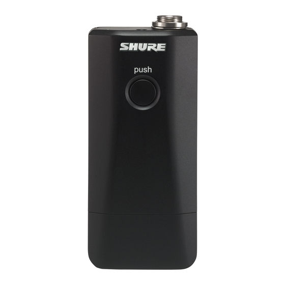
The bodypack secures to a belt or strap for hands-free, mobile communication. It features a Hybrid Bodypack (MXW1) TQG input for lavalier connection and an integrated omnidirectional microphone. The handheld enables presenters to communicate using legendary Shure SM58, SM86, BE Handheld (MXW2) TA58 and VP68 microphone cartridges. - Page 8 Shure Incorporated Access Point Transceiver (MXWAPT2, MXWAPT4, MXWAPT8) The Access Point Transceiver (2, 4 and 8 channel units) mounts to a wall or ceiling to manage encrypted, wireless audio con nections with microphones. As a system hub, it transports digital audio between the wireless microphones and other Dante de...
- Page 9 Shure Incorporated Networked Charging Station (MXWNCS2, MXWNCS4, MXWNCS8) The Networked Charging Station (2, 4 and 8 slot varieties) is capable of simultaneous charging MXW microphones. It also links microphones to access point channels and networks battery statistics to the control software.
- Page 10 MXWNCS8 charging stations (16 charging slots total). System Design and Technology Technology Overview of the Audio Path The MXW System combines Shure legendary audio quality with advanced digital networking technology. The following is an overview of the audio path: Wireless Audio The MXW transmitter converts speech into a digital signal that is transmitted wirelessly to the access point.
-
Page 11: Hardware Description
Shure Incorporated Hardware Description Audio Network Interface (ANI) Front Panel ① Input Channels Adds analog line- or aux-level signals to the digital network. When the device is associated to an MXW Group, inputs are automatically routed to Linked microphone channels (Input A to channels 1-4; Input B to 5-8). - Page 12 Shure Incorporated ⑦ Input Level Selector Set the selected channel to line- or aux-level to match the input signal. ⑧ Output Level Selector Set the selected channel to an output level that matches the connecting device: ◦ line: +4 dBu ◦...
- Page 13 Four-port gigabit switch for connecting components together for a single MXW Group, or for connecting multiple devices to a larger digital audio network. The following is a description of each port: Port Description Provides Power over Ethernet (PoE) for the Shure access point and functions as a standard gigabit Port 1 (PoE) port. 13/103...
-
Page 14: Access Point Transceiver (Apt)
Normal mode (default): this port functions the same as ports 2 and 3. Port 4 (Uplink) Uplink Mode: only transports control data. This mode blocks network audio and data for Shure Web Discovery Application, Dante Controller and Dante Virtual Soundcard. - Page 15 Shure Incorporated Color Status Green All routed receive channels are OK (receiving digital audio as expected). One or more connected receive channels experiencing a subscription error or is unresolved (trans mitting device is off, disconnected, renamed or has incorrect network setting).
-
Page 16: Networked Charger (Ncs)
Shure Incorporated Directional Antennas The access point contains multiple directional antennas to provide steady, reliable wireless communication with the micro phones. It sends and receives the RF signal in a cardioid pattern with the greatest sensitivity toward the face of the device. Al... - Page 17 Shure Incorporated ① Charging Slots (USB 3.0 Type A) Recharge and link microphones by connecting them to the USB slots on the charger. When the charger is associated to a group, the slots are mapped to access point channels (See Audio Channel Assignment for details).
-
Page 18: Microphone Transmitters
Shure Incorporated Monitors the charge status of the connected microphone in increments of <10, 10, 25, 50, 75, 100% (see Batteries for more detail). Additionally, the five LEDs flash for several seconds when the microphone has been successfully linked to the chan... - Page 19 Shure Incorporated MXW6, MXW8: Press and hold the dedicated power button for three seconds to turn the transmitter on or off. MXW1, MXW2: Press and hold the Mute/Active button for five seconds to turn the transmitter on or off. ② Mute/Active Button Changes the audio status from Active to Mute, or Mute to Active.
- Page 20 Shure Incorporated Status LED Table Status Description Active Green Ready to pass audio to network. Mute Audio is muted. Red Pulsing (long Audio is muted and the transmitter is in a hibernation state to con Standby off, short on) serve the battery.
- Page 21 Clip the transmitter to a belt or pocket. • For best results, the belt should be pressed against the base of the clip. Handheld (MXW2) The handheld enables presenters to communicate using legendary Shure SM58, SM86, BETA58 and VP68 microphone car tridges. 21/103...
- Page 22 Shure Incorporated Correct Microphone Placement • Hold the microphone within 12 inches from the sound source. For a warmer sound with increased bass presence, move the microphone closer. • Do not cover grille with hand. Boundary (MXW6/C, MXW6/O) The boundary transmitter sits on a table or desk to transmit speech while discreetly blending into any conference environment.
- Page 23 Shure Incorporated Desktop Gooseneck Base (MXW8) The gooseneck base is compatible with 5, 10, and 15” Microflex gooseneck microphones. Microphone Types Insert Microphone into Base 23/103...
-
Page 24: Rechargeable Batteries
Shure Incorporated MX405, MX410 & MX415 Bi-color Status Indicator MX405R, MX410R & MX415R Light Ring Rechargeable Batteries MXW lithium-ion rechargeable batteries use advanced chemistry that maximizes transmitter runtime. Power management from the control software provides detailed visibility to critical battery parameters such as charge status, battery capacity, and cycle count. - Page 25 Shure Incorporated Microphone Type Battery Model MXW8 gooseneck base MXW2 handheld SB902A Networked Charging Station (NCS) Slide the transmitter into the charging slot until it secures into place. The charge LEDs illuminate when the charge cycle begins. Regardless of Group association or network connection, any microphone can recharge in any NCS.
- Page 26 To return the charger to standard charging mode, power cycle the charger. Notes: • Shure rechargeable batteries require approximately 4 hours to fully recharge in High Efficiency Mode. Important: Because the charging LED indicators are disabled in High Efficiency Mode, you must manage the 4-hour recharge time using your own timer.
- Page 27 Shure Incorporated Battery Statistics on Control Software The MXW control software is used to manage battery information. Use the Monitor tab to view battery charging status: Monitoring Battery Charge Status In the Charging Station Displays the remaining time until the microphone battery is fully charged.
- Page 28 MXW control software > Preferences tab. Battery Replacement Lithium Ion Batteries experience a linear reduction in capacity. Shure recommends establishing a battery replacement sched ule customized to the client requirements and replacing batteries when the capacity is no longer acceptable.
-
Page 29: Installation
Shure Incorporated Important: After installing a new battery, reset the battery health statistics that are stored in the microphone following the steps in Reset the Microphone Battery Statistics in the previous section. MXW1, MXW6, MXW8 Battery Replacement Unscrew and open the battery door on the bottom of the transmitter. -
Page 30: Connecting Mxw Components
Shure Incorporated For systems with more than one APT, a DHCP router is recommended to connect equip ment. Ensure that it meets the following requirements: • Gigabit ports • Provides Class 0 PoE with at least 6.5W (for powering the MXWAPT) Gigabit DHCP Router (sys... - Page 31 Shure Incorporated *When Port 4 is set to Uplink mode, Shure Discovery Application support is restricted. Multiple Group System (>1 Access Point) When an installation requires more than eight channels, additional MXW components can be connected to expand the system.
-
Page 32: Rack Installation
Shure Incorporated Connect the router to Port 2, 3, or 4 on the Audio Network Interface Connect the Access Point Transceiver to the Port 1 of the Audio Network Interface. Connect the Network Charging Station(s) to an open port(s) on the Audio Network Interface. -
Page 33: Two-Channel Charger Wall Mount
Shure Incorporated Required Thread Exposure Use counterbore and washers as necessary depending on thickness of table NCS Mounting Template Two-Channel Charger Wall Mount The two-channel charger includes a wall-mount to provide quick microphone access and storage in a classroom or conference room. - Page 34 Shure Incorporated NCS2 Secures to a Classroom Wall Tip: Paint the mount to match the wall for a less obtrusive installation. Installation Determine the orientation and placement of the mount. Placement Orientation Wall Drawer or tray Leave room around the mount for cabling to the charging station.
- Page 35 Shure Incorporated Attach the mount to the wall. Use one set of screw holes depending on the orientation of the mount. Mount Screw Holes Align the charger on the mount and secure with the screws. Tip: Improve cable management using the cable tie holes on the mount.
- Page 36 Shure Incorporated NCS2 Mount Dimensions Side View 36/103...
- Page 37 Shure Incorporated Top View 37/103...
-
Page 38: Mount The Access Point Transceiver
Shure Incorporated Overall Dimensions Mount the Access Point Transceiver The directional antennas of the APT send and receive the RF signal in a cardioid pattern with the greatest sensitivity toward the face of the device. Always aim this side toward the microphone coverage area. - Page 39 Shure Incorporated • Keep at least eight feet between access points. • Mount with its reset button accessible, as it may be useful for troubleshooting. Important: Always perform a "walk around" test to verify coverage before using a wireless system during a speech or perfor...
-
Page 40: Power The Hardware
Shure Incorporated External Cover for Painting The Access Point is supplied with an external cover that can be painted to match the decor of the installation. After it has been painted and dried, it snaps onto the front plate of the device. -
Page 41: Open The Mxw Control Software
Shure Incorporated ③ Networked Charging Station (NCS) Connect the PS60 external power supply from the charger to an AC power source. Turn on the power switch. Fully Charge the Transmitters Whenever possible, charge to full the MXW transmitters before an event. Transmitters can be charged in any networked charg... -
Page 42: System Set Up
Open the Shure Web Device Discovery application. Open the application to view Shure devices on the network that use an embedded server for control software, such as the APT. You can use the Identify button to flash a device's LEDs for easy identification. - Page 43 Shure Incorporated Start with the APT and select the corresponding devices: • Chargers: for linking microphones • Audio outputs: for routing audio to analog outputs Group Components from the Network Once the group formed, microphones can be linked to channels using the charging station.
- Page 44 4. Select the Audio Output ® • Shure SCM820 IntelliMix Mixer. Dante-enabled SCM820s can be selected as the audio Device(s) output for the Group. This automatically routes the SCM820's aux input to the micro phones for personal monitoring (SCM820 aux left channel to MXW channels 1 - 4; aux right channel to MXW channels 5 - 8).
- Page 45 Shure Incorporated Device Availability When setting up a group or managing devices, it is important to understand the difference between open and associated de vices. A device that is not associated to a group is considered 'open.' Open devices are available Open Device for association by selecting the drop-down window in a Group row.
-
Page 46: Channel Routing Between Devices
Shure Incorporated Perform a factory reset on the devices (see the Factory Default section). On the front panel of the ANI, press both input level selection buttons at the same time and hold for five seconds. The Channel Select LEDs will illuminate green and the audio meter will flash to indicate that the association is successful. - Page 47 Shure Incorporated Gooseneck Microphones This setup is used to fill an 8-channel group with gooseneck microphones. Channels are rerouted when an additional charger is added to the group. (The gooseneck base is larger and covers two charger slots.) Mixture of Gooseneck and Boundary Microphones When 4-channel and 8-channel chargers are selected, group channels five through eight are automatically routed to the back row of the 8-channel charger.
-
Page 48: Link Microphones To Group Channels
Shure Incorporated Audio Output Examples 8-Channel Group 8-Channel SCM820 Digital Automatic Mixer Channels are routed to the eight outputs of the mixer. Two 4-Channel Audio Network Interfaces Channels are routed across both interfaces to fill the group. 4-Channel Group 8-Channel Audio Network Interface Channels are routed to the first four outputs of the interface. - Page 49 Shure Incorporated Microphones are Linked to access point channels according to the arrangement in the charger. Note: 2-channel chargers do not support gooseneck microphones. 1. Arrange microphones in the charger. Connecting the Microphone to the Charger Slot Use the control software or the charging station to Link the microphones to APT channels. If desired, this feature can be disabled on the charging station so that Linking can only be per...
-
Page 50: Preparing A Backup Microphone
Shure Incorporated Monitor Tab Preparing a Backup Microphone Prepare an alternate microphone for each channel for more reliable and flexible events. Two MXW microphone transmitters can be linked to the same channel, providing the option of either microphone for use. - Page 51 Shure Incorporated Charged Backup Microphones Prepare for long events by linking fully-charged microphones as backups Shared Resources Easily add a temporary microphone without unlinking the most commonly used microphones. One Active Mic per Channel Only one microphone will operate on the channel at a time, blocking the second microphone from interfering with the RF and audio performance.
-
Page 52: Exchanging Or Removing A Component
Shure Incorporated Open the MXW control software and go to the Monitor tab. Select Secondary in that channel's link slot. Select the Link button on the channel strip to link that microphone. The charger LEDs will flash when the procedure is complete. -
Page 53: Large Installations
Shure Incorporated *A comprehensive list of MXW command strings are available on the Shure website: www.shure.com, search "command strings". Large Installations Shure SystemOn Software For Managing Large Systems Shure SystemOn Audio Asset Management Software provides a central platform for managing mission critical, largescale de... - Page 54 Group on the Configuration tab, there will be a pop-up warning "Are You Sure?". If Yes is selected, the browser will close and a new Configuration Master is automatically selected. Use the Shure Discovery Application to re-open the control interface from any remaining MXW Access Point.
-
Page 55: Wireless Management
Shure Incorporated Lock the Configuration for Best System Performance After setting up all your MXW groups, lock the configuration to minimize network traffic. Wireless Management Overview of Channel Coordination The MXW system operates using time division multiple access (TDMA) to carry MXW channels (audio and control data) within defined RF spectrum. -
Page 56: Scanning Available Rf Spectrum
Shure Incorporated Density Mode Band Region Standard (SD) High (HD) Taiwan Scanning Available RF Spectrum The MXW Wireless components operate in unlicensed spectrum that is shared with other wireless devices operating in the same area, such as cordless phones, walkie-talkies and intercoms. The MXW control software features a scanning tool that surveys the RF spectrum for these devices. -
Page 57: Phs Detection
Shure Incorporated Displays the percentage of available spectrum Radio Frequency Interference (RFI) The scanner analyzes the spectrum and divides the data into three categories: No/Low (Green) Clean RF available for MXW system. Moderate (Yellow) Some moderate interference is detected, still usable by the MXW system. -
Page 58: Identifying Phs Detection Errors
Shure Incorporated Excluding PHS Bands To operate in the JDECT spectrum without worrying about PHS interruption, set the MXW access point (APT) to exclude PHS channels. This reduces the number of MXW channels available, but ensures that microphones will never be overridden in the event of PHS detection. -
Page 59: Setting Rf Power
Shure Incorporated Caution: Audio is temporarily interrupted during spectrum scan. Do not initiate a scan during a live meeting. Running Spectrum Scans Dock all microphones in chargers to decrease MXW affect on the RF spectrum. Open the Web Discover application and view all APTs on the network. -
Page 60: Using Multiple 2- Or 4-Channel Access Points
Shure Incorporated RF Coverage Optimal Placement of the Access Point Place the Access Point in the center of the installation for best coverage Using Multiple 2- or 4-Channel Access Points The MXW access point uses two sets of antennas to cover the operating spectrum. Each antenna set covers half of the times... - Page 61 The MXW system must be operating on a minimum firmware version of 2.0.0. Set Up Open the MXW control software using the Shure Web Device Discovery application. Go to the Utility page. Open the Device Properties window for the two- or four-channel access point (MXWAPT2 or MXWAPT4).
-
Page 62: Networking
Shure Incorporated Open the Device Properties for the adjacent APT2 or APT4. Set the unit to Mode B (Device Propterties > RF Mode Settings > RF Coordination Mode). Select Add Updates to save the setting and close the window. -
Page 63: Configuring Ip Settings
The MXW control software coordinates IP updates across the entire system of devices. To configure the IP properties, follow these steps: Open the MXW control software from the Shure Web Device Discovery app. Go to the Utility tab. Adjust IP settings for each device by selecting the Device Properties. - Page 64 MXW devices transport two types of data over the network: Shure Control and Network Audio. Shure Control The Shure Control carries data for the control software operation, firmware updates and 3rd party control systems (AMX, Crestron). This data is transported to all MXW components connected to the network.
-
Page 65: Advanced Setup
Uplink mode blocks multicast traffic from Port 4 of the ANI, restricting network audio and Shure Discovery data. Because the device will not show up in the Shure Device Discovery application, the IP address of the control software must be recorded to access the server. - Page 66 Tip: For larger wireless microphone configurations, it’s recommended to increase the multicast transmission rate to provide adequate bandwidth to the MXW control software. Important: For best performance, use a Wi-Fi router that does not limit the multicast rate to 1-2 Mbps. Shure recommends the following Wi-Fi router brands: • Cisco •...
-
Page 67: Connecting To An External Control System
Connecting to an External Control System The MXW System connects to an AMX or Crestron control system via the Ethernet. Use only one controller per system to avoid messaging conflicts. For a comprehensive list of MXW command strings, visit: http://shure.custhelp.com/app/answers/ detail/a_id/5207 •... - Page 68 MAC address, as array of 6 bytes Note: The Shure device should respond in less than one second on a typical network. If there is no response, try sending the query again after verify ing the destination IP address and port number.
-
Page 69: Software
Shure Web Device Discovery Application The Shure Web Device Discovery application is used to access the graphical user interface (GUI) of a Shure device. The GUI opens in a web browser to provide comprehensive device management. Any computer networked to the device can access the GUI with this application. -
Page 70: Mxw System Control Software
Shure Incorporated MXW System Control Software The MXW control software allows comprehensive system control and monitoring from a computer. It is hosted from an embed ded server in the MXW Access Point, and is accessible when properly networked to a computer. All hardware functions can be adjusted using this software interface. - Page 71 ③ Log Off Logs the user out of the software. ④ Shure Link Links to the Shure website at www.shure.com. ⑤ Language Selection Selects the language for the control software interface. This setting will be saved to the computer. 71/103...
- Page 72 Shure Incorporated Monitor Tab ① Access Point Selection Determines which Access Point displays on the tab. ② Density Mode Selection Displays the density mode as selected in the APT device properties. ③ Spectrum Scanner Opens the Spectrum Scanner window. See Scanning Available RF Spectrum section for more details.
- Page 73 Shure Incorporated Selects the which microphone displays on the channel strip. Note: One microphone is on-air per channel, though an alternate microphone can be prepared in the secondary link slot. ⑦ Identify Button Commands the microphone to flash its LEDs to easily identity which device corresponds to the channel.
- Page 74 Shure Incorporated Displays the microphone type. ⑯ Link/Unlink Buttons For setting up a single audio channel. Links the microphone to the primary or secondary link slot (as selected at the top of the channel strip). ◦ Link: Links the microphone from the corresponding charging slot.
- Page 75 Shure Incorporated ③ Link Button Links all microphones in the charger to channels in the associated Group. ④ Configuration Lock Increases the number of MXW components that can operate on the same network. It is best practice to lock the configura...
- Page 76 Shure Incorporated Utility Tab ① Export Button Exports MXW device data to a text file (.csv). ② Configuration Filter When checked, the table displays data for only the devices that belong to the Configuration or are open for association. Un- check the filter to view all MXW devices on the subnet.
- Page 77 Displays device name as defined in the Configuration tab or channel name as defined in the Monitor tab. ⑦ IP Address Control Displays the IP Address of the control network interface (Shure control data). ⑧ IP Address Network Audio Displays the IP Address of the Network Audio network interface (Dante digital audio data).
- Page 78 Note: Use with caution, as this could break the routing configuration previously made in DC, causing audio interruptions. ③ Serial Number The unique identifier used to register the device at the Shure website, guarantee the warranty, and troubleshooting with customer support.
- Page 79 View and adjust IP settings for the device's network interface(s). Network settings are different for each device. See the Networking section for configuring each MXW device. ◦ Control: Shure control (software interface operation, firmware updates, Shure Device Discovery application). ◦ Network Audio: Dante network audio (digital audio networking and Dante software).
- Page 80 Shure Incorporated Preferences Tab All preferences apply to each device in the Configuration. ① Switch Behavior Customize the switch on each transmitter type. ◦ Toggle (default): Press and release the button to change the status to Active or Mute. ◦...
- Page 81 Shure Incorporated Active Mute Solid Red External LED Control *Not available for MX400R series gooseneck microphones ④ Mute Preference ◦ Local Mute - Individual (default): Each transmitter is muted individually. ◦ Local Mute - All: All transmitters mute when any transmitter is muted.
-
Page 82: Control Software For The Mxw Audio Network Interface
Configuration. ⑭ Register the Product Link Links to Shure website for product registration. Control Software for the MXW Audio Network Interface The MXW Audio Network Interface features a control software to mange the analog inputs and outputs of the MXW system, in addition to the 4-port gigabit switch on the back panel of the network interface. - Page 83 Shure Incorporated ② Identify Button This button sends a command to the hardware to flash front-panel LEDs for easy identification. ③ Security Level Displays the access level of the user: Administrator, Technician, or Guest. ④ Log Off Logs the user out of the software.
-
Page 84: Dante Software By Audinate
◦ Switched Mode (default): Full Ethernet support on port 4. ◦ Uplink Mode: Only control data is transported. Multicast traffic for Dante digital audio and the Shure Web Device Discov ery application is restricted. ⑪ Front Panel Lockout Disables the front panel controls on the hardware. Channels can still be selected for monitoring at the headphone jack. -
Page 85: Firmware Updates
MXW device on the network, open the Utility page of the MXW control software. The format for Shure device’s firmware is MAJOR.MINOR.PATCH. (Ex. 1.6.2 where 1 is the Major firmware level, 6 is the Mi nor firmware level, and 2 is the Patch firmware level.) At minimum, devices that operate on the same subnet should have identical MAJOR and MINOR release numbers. - Page 86 Shure Incorporated Audio Problem Indicator Solution Check cables Check that transmitters are on and channels are un-muted Check that the input meters are OK on the Monitor tab of the MXW control software. Attenuate if the channel is clipping. Check the output meters on the Audio Network Interface (ANI) front panel Green and in the ANI control software.
-
Page 87: Additional Resources
If a device isn't appearing on the network after trying troubleshooting methods, perform a reset on the specific hardware to re turn the device to default settings. Factory default settings are designed for automatic compatibility with other Shure networked devices. - Page 88 Shure Incorporated From the Hardware Access Point Transceiver Press and hold the recessed reset button for 10 seconds. The network audio status LED will briefly turn off to indicate the unit is rebooting. CAUTION: A factory reset deletes all Group associations and microphone Links saved in the device.
-
Page 89: Accessories And Model Variations
Shure Incorporated Accessories and Model Variations MXW Device Description Part Number 8-Channel Access Point Transceiver MXWAPT8 4-Channel Access Point Transceiver MXWAPT4 Access Point Transceiver 2-Channel Access Point Transceiver MXWAPT2 Mounting Plate 65A20096 Paintable Cover 65A20030 8-Channel Audio Network Interface MXWANI8... - Page 90 Shure Incorporated MXW Device Description Part Number Black MXW gooseneck base trans mitter (without gooseneck micro MXW8 phone) White MXW gooseneck base Gooseneck Base transmitter (without gooseneck MXW8W microphone) Gooseneck microphone see table Battery SB901A USB Charger Varies by region; see table...
- Page 91 Shure Incorporated Microphone Description Polar Pattern Length Part Number Supercardioid 10" (25.4 cm) MX410LP/S Cardioid 15" (38.1 cm) MX415LP/C Supercardioid 15" (38.1 cm) MX415LP/S 5" (12.7 cm) MX405RLP/N Light ring indicator No cartridge included 10" (25.4 cm) MX410RLP/N 15" (38.1 cm)
-
Page 92: Microflex Wireless Specifications
Shure Incorporated USB Charger USB Charger by Region Part Number SBC10-USB-A SBC10-USBUK-A Europe SBC10-USBE-A Australia SBC10-USBAZ-A Japan and Taiwan SBC10-USBJTW-A Brazil SBC10-USBR-A India SBC10-USBIN-A Microflex Wireless Specifications System RF Carrier Frequency Range Band Region Frequency Range USA , Canada , Mexico 1920–... -
Page 93: Transmitters
Shure Incorporated Signal-to-Noise Ratio <90 dB Aweighted Cable Requirements Cat 5e or higher Dimensions 61 x 150 x 168 mm Weight 650 g Operating Temperature Range 5℃ (41℉) - 40℃ (104℉) Transmitters Gain Adjustment Range −25 to +15 dB (in 1 dB steps) Maximum Input Level Mic gain @ −16 dB... - Page 94 Shure Incorporated Housing Molded Plastic Recommended Storage Temperature Range 0°C (32°F) to 25°C (77°F) MXW1 Hybrid Bodypack Transmitter Microphone Connector 4-Pin male mini connector (TA4M), See drawing for details Input Impedance @ 1 kHz >20 kΩ Internal Microphone Omnidirectional (20 Hz – 20 kHz) Dimensions 22 mm x 45 mm x 99 mm (0.9 in.
-
Page 95: Access Point Transceiver (Apt)
23 mm x 44 mm x 114 mm (0.9 in. x 1.75 in. x 4.5 in.) H x W x D Weight 108 g (3.8 oz.) with batteries MXW8 Gooseneck-Base Transmitter Microphone Connector 6-pin connector for Shure MX405/10/15 Configuration Unbalanced Input Impedance @ 1 kHz >20 kΩ... -
Page 96: Networked Charging Station (Ncs)
Shure Incorporated Antenna Type Internal, Spatial Diversity, Circular Polarization Antenna Gain Average 0.5 dBi Peak 3.0 dBi Housing Molded Plastic, Cast Zinc Dimensions 24 mm x 170 mm x 170 mm (1.35 in. x 6.7 in. x 6.7 in.), H x W x D... -
Page 97: Audio Network Interface (Ani)
Shure Incorporated NCS4 1.7 kg (3.7 lbs) NCS2 0.8 kg (1.8 lbs) Audio Network Interface (ANI) Audio Network Interface (ANI) Audio Frequency Response 20 Hz to 20 kHz (+1, −1.5 dB) Dynamic Range 20 Hz to 20 kHz, A-weighted, typical... - Page 98 Shure Incorporated Analog Connections Outputs Clipping Level (minimum) Configuration Impedance Line Active Balanced 310 Ω +26.2 dBV +16.2 dBV −3.8 dBV Input(s) Clipping Level (minimum) Configuration Impedance Line Active Balanced 10.6 kΩ +23.8 dBV +10.8 dBV Headphone Output 6.35 mm (1/4") TRS, 100 mW, 350 Ω, dual mono (will drive stereo phones) 0 dBV=1 V RMS 0 dBu=0.775 V RMS...
-
Page 99: Transmitter Output Power
Shure Incorporated Network Addressing Capability DHCP, link-local, static Transmitter Output Power Bands: Z10, Z11, Z14, Z15 MXW1 Setting Medium High Maximum MXW2 Setting Medium High Maximum MXW6, MXW8 Setting Medium High Maximum Band: Z12 MXW1, MXW6, MXW8 Setting Medium High... -
Page 100: Wiring Diagram
Shure Incorporated Maximum MXW2 Setting Medium High Maximum Wiring Diagram TA4M Connector Audio Network Interface (ANI) 100/103... -
Page 101: Safety Information
EMC conformance testing is based on the use of supplied and recommended cable types. The use of other cable types may degrade EMC performance. Changes or modifications not expressly approved by Shure Incorporated could void your authority to operate this equipment. -
Page 102: Information To The User
Shure Incorporated Please follow your regional recycling scheme for batteries, packaging, and electronic waste. Note: This device is not intended to be connected directly to a public internet network. Information to the user This device complies with part 15 of the FCC Rules. Operation is subject to the following two conditions: This device may not cause harmful interference. -
Page 103: Trademarks
This product meets the Essential Requirements of all relevant European directives and is eligible for CE marking. The CE Declaration of Conformity can be obtained from Shure Incorporated or any of its European representatives. For contact information please visit www.shure.com The CE Declaration of Conformity can be obtained from: www.shure.com/europe/compliance...
Need help?
Do you have a question about the Microflex MXV Series and is the answer not in the manual?
Questions and answers