
Related Manuals for AMX MVP-9000i-GB


Summary of Contents for AMX MVP-9000i-GB
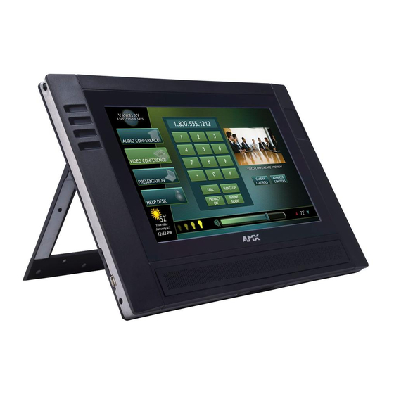
- Page 1 IN STR U CT IO N MAN U AL M V P - 9 0 0 0 i ® ® 9" MODERO VIEWPOINT TOUCH PANE L WITH INTERCOM MVP- 900 0i- GB MVP- 900 0i- GW...
-
Page 2: Copyright Notice
COPYRIGHT NOTICE AMX© 2015, all rights reserved. No part of this publication may be reproduced, stored in a retrieval system, or transmitted, in any form or by any means, electronic, mechanical, photocopying, recording, or otherwise, without the prior written permission of AMX. Copyright protection claimed... - Page 3 Anyone performing field maintenance on AMX equipment should use an appropriate ESD field service kit complete with at least a dissipative work mat with a ground cord and a UL listed adjustable wrist strap with another ground cord WARNING: Do Not Open! Risk of Electrical Shock.
- Page 4 This product contains batteries that are covered under the 2006/66/EC European Directive, which cannot be disposed of with normal household waste. Please follow local regulations. You may obtain a free copy of the Declaration of Conformity by visiting http://www.amx.com/techcenter/certifications.asp. WEEE NOTICE: This appliance is labeled in accordance with European Directive 2012/19/EU concerning waste of electrical and electronic equipment (WEEE).
-
Page 5: Table Of Contents
Table of Contents Table of Contents Introduction ....................15 Overview ......................... 15 Common Application ..........................15 Features ..............................15 Memory........................... 17 Connector Locations ...................... 17 Basic Operation ......................17 Powering on the MVP-9000i................... 17 Intercom Microphone..................... 17 Stylus ..........................17 Kick Stand........................18 Audio/Video Capabilities.................... - Page 6 Table of Contents Configuring Communication ................30 Overview ......................... 30 IR Communication......................30 Modero Setup and System Settings ................31 Accessing the Setup and Protected Setup Pages ................31 Setting the Panel’s Device Number ...................... 31 Wireless Settings - Wireless Access Overview............... 31 DHCP ..............................
- Page 7 Table of Contents Panel Information Page - File ....................... 53 Panel Information Page - Project ......................54 Protected Setup Pages ..................55 Overview .......................... 55 System & Panel Options page ..................56 Security Settings ..........................57 Installing Firmware ..........................57 System Settings Page...................... 58 System Settings - Master........................
- Page 8 Table of Contents Upgrading Firmware via USB stick or MicroSD card ............80 Upgrading from Previous Firmware ................81 Upgrading Firmware Via NetLinx Studio ................. 82 Step 3: Confirm and Upgrade the firmware via the USB port............... 83 A Special Note for Network Interface Connections ............85 Reverting the MVP-9000i to Factory Default Firmware ..........
- Page 9 Table of Contents ^BCF ....................................100 ?BCF..................................... 100 ^BCT ....................................101 ?BCT..................................... 101 ^BDO ....................................101 ^BFB ....................................102 ^BIM ....................................102 ^BLN ....................................102 ^BMC ....................................103 ^BMF....................................104 ^BMI ....................................105 ^BML ....................................105 ^BMP....................................105 ?BMP ....................................106 ^BNC ....................................
- Page 10 Table of Contents ^UNI ....................................119 Miscellaneous MVP Strings......................... 120 undock-<user>..................................120 UNDOCKED ................................... 120 SWAP ....................................120 dock ..................................... 120 MVP Panel Lock Passcode Commands ....................120 ^LPC..................................... 120 ^LPR..................................... 120 ^WLD....................................120 Text Effects Names ....................... 121 ^LPS..................................... 121 Panel Runtime Operations....................
- Page 11 Table of Contents ^ICM-MICLEVEL................................... 129 ^ICM-MUTEMIC................................... 129 SIP Commands ......................130 Panel to Master ........................... 130 ^PHN-AUTOANSWER ................................130 ^PHN-CALL ..................................130 ^PHN-DECLINE ..................................130 ^PHN-INCOMING................................. 130 ^ICM-SPEAKERLEVEL ................................130 ^PHN-LINESTATE ................................131 ^PHN-MSGWAITING................................131 ^PHN-PRIVACY ..................................131 ^PHN-REDIAL ..................................131 ^PHN-TRANSFERRED ................................
- Page 12 Step 1: Configure The Panel For a USB Connection Type ..............147 Step 2: Prepare NetLinx Studio For Communication Via the USB Port..........148 AMX Certificate Upload Utility ..................148 Uploading a Certificate File ..................148 Erasing All Certificates From the Touch Panel ................... 149 Appendix C: Troubleshooting ..............
-
Page 13: Introduction
Available in your choice of black or white. Capacitive touch buttons provide simple (up/down) or sophisticated control (up/down, right/left, select). VoIP Intercom and SIP Telephone (requires AMX SIP Gateway) Ready. 802.11a/b/g WiFi for two-way network communications. ... - Page 14 Transmit IR (transmit only) over 20 feet (6.10 m) from the panel. • IR emitters on G4 panels share the device address number of the panel. • Transmits AMX fixed frequencies at 38KHz and 455KHz and third-party user-programmable frequencies from 20KHz to 1.5MHz Certifications: •...
-
Page 15: Memory
The MVP-9000i comes with a unique touchscreen stylus that slides into a storage groove on the left side of the device when not in use. Replacement styluses may be ordered in a 3-pack (black, FG5966-21; white, FG5966-22) from www.amx.com. MVP-9000i - Instruction Manual... -
Page 16: Kick Stand
45° C (113° F). The temperature is determined by a combination of the ambient temperature where the panel is located, plus temperature increases normally occurring inside electronic devices containing batteries. AMX has implemented battery temperature monitoring features to maximize the rate of battery charging, while staying within industry temperature guidelines. -
Page 17: Starting Picture View
Introduction Starting Picture View Connect a USB drive to the device or insert a microSD memory card into the microSD memory card slot. Picture View will automatically recognize all available images on the drive or memory card and start displaying them on the touchscreen. When the images begin to display, touch any place on the touchscreen to open the configuration popup menu (FIG. - Page 18 Introduction To swap from a wireless connection to a wired one, simply place the panel in a Table Docking Station or Wall Docking Station. To swap from a wired connection to a wireless connection, you must first initiate an undock request. This can be done with the undock button on the Docking Station, or with the Undock Panel button in the System &...
-
Page 19: Accessories
• PS-POE-AT High Power PoE Injector (FG423-81) • Ethernet cable - black (ECA5967-22BL) (for MVP-TDS-9-GB) • Ethernet cable - white (ECA5967-22WH) (for MVP-TDS-9-GW) Other AMX • MVP-9000i Modero Viewpoint Widescreen Touch Panel with Intercom - Black (FG5967-01) Equipment: • MVP-9000i Modero Viewpoint Widescreen Touch Panel with Intercom - White (FG5967-02) -
Page 20: Recharging
Accessories To Ethernet cable connected To input port on to PS-POE-AT the MVP-TDS-9 MVP-TDS-9 cable FIG. 7 To connect the MVP-TDS-9 to the PS-POE-AT via the special Ethernet cable: Connect the terminal end of the cable to the PWR connector on the bottom of the MVP-TDS-9. To prevent wear on the power supply cord and assure that the device’s base is in full contact with the table surface, press the cord into the locking groove running across the bottom of the device (FIG. -
Page 21: Wall Docking Station
• MVP-WDS-9 Wall Docking Station Template (68-5967-01) • PS-POE-AT High Power PoE Injector (FG423-81) Other AMX • MVP-9000i-GB Modero Wireless Touch Panel, Black (FG5967-01) Equipment: • MVP-9000i-GW Modero Wireless Touch Panel, White (FG5967-02) • MVP-TDS-9-GB Black Table Docking Station (FG5967-10) •... -
Page 22: Unlocking The Touch Panel
Accessories The MVP-9000i touch panel remains locked in the MVP-WDS-9 until unlocked by the user. This may be done by entering an appropriate password (please refer to the Passwords section on page 73 for more information), or by pressing the Security Release button on the front of the device in emergencies. -
Page 23: A Note About Wall And Rack Installation
FIG. 12 shows an AMX device installed in a wall with a filled volume (such as with insulation or concrete), as well as with a closed volume (such as between studs in an otherwise finished wall). The diagram shows how heat generated by the device or other devices may have no way to escape, and may build up to levels that may affect device operation. -
Page 24: Installing The Mvp-Wds-9
Accessories Installing the MVP-WDS-9 Since the Wall Docking Station is intended to be affixed to a wall or other permanent structure, care must be taken to ensure its proper installation to prevent potential damage to the MVP-9000i placed within. NOTE: Other than wall installation tools, the only tool required for this installation is a #2 Phillips screwdriver. Installing the Wall Docking Station and Plastic Back Box The Plastic Back Box has two pairs of knockouts at the top of the box and four (4) lockdown wings attached to the box with Phillips- head screws. -
Page 25: Installing The Optional Metal Rough-In Box
Accessories Attach the included snap-on ferrite to the Ethernet cable, as close to the RJ-45 connector as possible. Attach the cable to the Ethernet Port (FIG. 15). Recommended Ethernet installation Recommended USB installation Knockout placement in back box Ethernet port Ferrite installation position Recommended Ethernet cable path MVP-WDS-9 - Ethernet cable path... -
Page 26: Pre-Wall Installation Of The Cb-Mvp-Wds9
Accessories Pre-Wall Installation of the CB-MVP-WDS9 Remove the rough-in box cover (A in FIG. 16) before installation of the Rough-In Box (B). NOTE: The cover MUST be removed before drywall installation. The cover may be reinstalled after drywall installation using 4-40 screws (not included). - Page 27 Accessories When disconnecting from a Docking Station, the MVP-9000i will attempt to switch from a Wired to Wireless connection. If the touch panel is unable to connect to a wireless network, a confirmation window appears warning that the panel will lose its network connection (FIG.
-
Page 28: Configuring Communication
IR Communication In certain situations, the MVP-9000i may be used as an infrared remote device for other AMX controllers. The device can transmit IR over 20 feet (6.10 m) from the panel at AMX frequencies of 38KHz and 455KHz, and third-party device frequencies between 20KHz and 120KHz. -
Page 29: Modero Setup And System Settings
Configuring Communication Modero Setup and System Settings All AMX Modero panels, including the MVP-9000i, feature on-board Setup pages. Use the options in the Setup pages to access panel information and make various configuration changes. Accessing the Setup and Protected Setup Pages At any time, hold the bottom left capacitive touch button and the bottom of the directional pad for 3 seconds. -
Page 30: Dynamic Frequency Selection (Dfs)
Because this can result in connection loss while the network is moving to the new frequency, AMX has restricted the 5GHz operation at this time to only those channels that are allowed without supporting DFS. -
Page 31: Configuring Wireless Network Access
Configuring Communication Conf iguring Wireless Network Access The first step in connecting the MVP-9000i to a wireless network is to configure the wireless communication parameters within the device’s System Settings page. This is done via the System Settings page, which allows configuration of the IP Address, System Number and Username/Password information assigned to the target Master. -
Page 32: Using The Wireless Site Survey Tool
Configuring Communication Press the IP Address field to open a keyboard and enter the Static IP Address provided by the System Administrator. Press OK after entering the IP address information and repeat the same process for the Subnet Mask and Gateway fields. Press the optional Host Name field to open the keyboard and enter the Host Name information. -
Page 33: Step 2: Configure The Card's Wireless Security Settings
Configuring Communication For any other security mode, clicking Connect will open the Enterprise Mode popup window (FIG. 27). Different EAP methods are selectable from the Security Type button. Simple Mode popup window Enterprise Mode popup window Wireless Security: Simple Mode popup window FIG. -
Page 34: Step 3: Choose A Master Connection Mode
Configuring Communication Step 3: Choose a Master Connection Mode The MVP-9000i requires a decision on the type of connection to be made between it and the Master. To establish a Master connection: From the System Settings page, select the Master tab if it is not already selected. The Current Connection field displays the current connection availability (FIG. -
Page 35: Touch Panel Setup
Configuring Communication Touch Panel Setup To prepare the MVP-9000i for Ethernet for USB communication: Turn on the MVP-9000i and wait for the device to finish booting up. Insert the mini-USB end of the USB Programming Cable into the mini-USB port on the device. Insert the other end into the appropriate USB port on the computer containing the files to be downloaded. - Page 36 From the Windows XP desktop, click on Start > Settings > Network Connections. This opens a window listing the currently active network connections. Select the connection that is specific to AMX USB Device Link. Right click and select Properties. In the Local Area Connection 3 Properties window (FIG. 34) under the General tab, select Internet Protocol (TCP/IP) and click on Properties.
-
Page 37: Configure A Virtual Netlinx Master Using Netlinx Studio
Configuring Communication Conf igure a Virtual NetLinx Master using NetLinx Studio A Virtual NetLinx Master (VNM) is used when the target panel is not actually connected to a physical NetLinx Master. In this situation, the PC takes on the functions of a Master via a Virtual NetLinx Master. This connection is made by either using the PC’s Ethernet Address (via TCP/IP using a known PC’s IP Address as the Master) or using a direct mini-USB connection to communicate directly to the panel. -
Page 38: Ethernet
Configuring Communication Ethernet When using Wireless Ethernet, press the listed Mode in the Master tab to toggle through the available connection modes: Connection Modes Mode Description Procedures None No connection None Auto The device connects to the first master that responds. This Setting the System Number: setting requires setting the System Number. - Page 39 By selecting URL, the System Number field becomes read-only (grey) because the panel pulls this value directly from the communicating target Master, virtual or not. A Virtual Master system value can be set within the active AMX software applications such as NetLinx Studio, TPD4, or IREdit.
-
Page 40: Using G4 Web Control To Interact With A G4 Panel
NOTE: G4 Web Control cannot display page transitions or Dynamo images that are accelerated in hardware. NOTE: Verify your NetLinx Master (ME260/64 or NI-Series) has been installed with the latest f irmware KIT f ile from www.amx.com. Refer to the NetLinx Master instruction manual for more detailed information on the use of the new Web-based NetLinx Security. - Page 41 Configuring Communication Once activated, this page displays links to G4 panels running the latest G4 Web Control feature that were previously set up and activated on the device. Compatible devices field (showing G4 WebControl links) G4 panels Compression Options Manage WebControl Connections page (populated with compatible panels) FIG.
- Page 42 Configuring Communication Enter the Web Control session password into the Session Password field (FIG. 45). This password was previously entered into the Control Password field within the G4 Web Control Settings page on the panel. 10. Click OK to send the password to the panel and begin the session. A confirmation message appears stating "Please wait, Initial screen loading.".
-
Page 43: Setup Pages
Protected Setup pages (page 56). Separate TPDesign4 files must be downloaded for each mode. These files are available at www.amx.com. To switch between Landscape and Portrait Mode, please refer to the System & Panel Options page on page 56. -
Page 44: Navigation Buttons
Setup Pages Setup Page (Cont.) Navigation Buttons: The buttons along on the left half of the page provide access to secondary Setup pages (see following sections). Connection Status: Displays whether the panel is has external communication, as well as the encryption status of the Master, the connection type (Ethernet or USB), and to which System the panel is connected. -
Page 45: Audio Page
Setup Pages Display Page (Cont.) Panel Brightness: Sets the display brightness and contrast levels of the panel. Press the Brightness Up/Down buttons to adjust the brightness level. Range = 0 - 100. Note: Be careful not to turn down the brightness too low to be able to see the Setup page. Inactivity Page: Indicates the length of time that the panel can remain idle before automatically flipping to a pre-selected page. -
Page 46: Power Management Page
Setup Pages Power Management Page The options on the Power Management page allow setting of power warning preferences and battery status information, and adjustment of the display times for battery warnings (FIG. 51) Power Management page FIG. 51 Power Management Page Back: Saves all changes and returns to the previous page. -
Page 47: Battery Conditioning
Test button on the Power Management page.If any fault exists in the battery, a confirmation dialog box appears (FIG. 52) that warns of the fault. For more information on the fault, please contact AMX Customer Support, and give the fault code from the confirmation dialog. - Page 48 Setup Pages To use the Test function: Dock the MVP-9000i in a Table or Wall Docking Station prior to testing the battery. Press the Test button. If the battery does not require conditioning, a popup opens that reads "The battery is functioning normally and does not currently need maintenance.
-
Page 49: Date/Time Page
Setup Pages Battery Maintenance Is Paused popup window FIG. 57 Date/Time Page The options on the Date/Time page (FIG. 58) allows setting and adjusting of time and date information on the MVP-9000i. If the time and/or date on the Master is modified, all connected devices will be updated to reflect the new information. Date/Time page FIG. -
Page 50: Panel Information Page
Setup Pages Set Date/Time popup window FIG. 59 Set Date/Time Popup Window Set Date/Time: Use the Up/Down arrow buttons to adjust the MVP-9000i’s calendar date and time. A white outline around the field indicates which field is currently selected. • Year range = 2000 - 2199 •... -
Page 51: Panel Information Page - Config
Setup Pages Panel Information Page - Conf ig The Conf ig tab provides information on the panel’s configuration (FIG. 61). : Panel Information Page - Config FIG. 61 Panel Information Page - Conf ig Back: Saves all changes and returns to the previous page. WiFi/Wired icon: The icon to the left of the Connection Status Icon displays whether the current connection to the Master is Wireless (image of a radio antenna) or Wired (image of three networked computers). -
Page 52: Panel Information Page - Project
• This information is specified in TPD4 (Project Properties > IR Emitters & Receivers tab). • For example, if you set the AMX IR 38K Port to 7 and then put a button on the panel with a channel code of 5 and a port of 7, it will trigger the IR code in slot 5 of the AMX IR 38K Port. -
Page 53: Protected Setup Pages
Protected Setup Pages Protected Setup Pages Overview The Protected Setup page (FIG. 64) provides secured access to advanced panel configuration options, including communication and security settings. The Protected Setup page is accessed through the Setup page (please refer to the Setup Pages on page 45). Protected Setup page showing default values FIG. -
Page 54: System & Panel Options Page
Releases the panel from the Table Docking Station (page 21) or the Wall Docking Station (page 23). Remove Pages: Removes all TPD4 touch panel pages currently on the panel, including the pre-installed AMX Demo pages. This option invokes a Confirmation dialog, prompting you to confirm your selection before removing the panel pages. -
Page 55: Security Settings
Web Control. Although the security password features are immediate, a reboot must occur for all the new security mode features to take full effect. For more information on configuring AMX devices for a secure environment, please refer to the guide Security Prof iles: Conf iguring AMX Devices For Installation Into a Secure Environment, available at www.amx.com. -
Page 56: System Settings Page
Protected Setup Pages System Settings Page The System Settings page (FIG. 69) displays the NetLinx Master’s communication settings. This page contains four tabs: Master, Wired, WiFi, and USB. Each of these tabs is covered in a separate section. System Settings - Master The Master tab controls the method of connection to a NetLinx Master. -
Page 57: System Settings - Wired
Protected Setup Pages System Settings - Wired Use the options on the Wired Tab (FIG. 70) to configure communication settings for Ethernet communication with the MVP-9000i. System Settings - Wired Tab FIG. 70 System Settings - Wired Tab Back: Saves all changes and returns to the previous page. WiFi/Wired icon: The icon to the left of the Connection Status Icon displays whether the current connection to the Master is Wireless (image of a radio antenna) or Wired (image of three networked computers). - Page 58 Protected Setup Pages System Settings - WiFi Tab Back: Saves all changes and returns to the previous page. WiFi/Wired icon: The icon to the left of the Connection Status Icon displays whether the current connection to the Master is Wireless (image of a radio antenna) or Wired (image of three networked computers).
-
Page 59: Security Modes
Protected Setup Pages System Settings - WiFi Tab - Page 2 (Cont.) AP MAC: This field contains the Access Point MAC address in which the panel is connected. It also is used to display supplicant status during authentication and association as the panel first connects to the access point. Channel: The RF channel being used for connection to the AP (read -only). -
Page 60: Open
Protected Setup Pages Open From the Security Modes options, press the Simple button to open the Wireless Security: Simple Mode page. Scroll through the Security Type options to select Open (FIG. 75). Wireless Security: Simple Mode - Open FIG. 75 Open security does not utilize any encryption methodology, but requires an SSID (alpha-numeric) entry. -
Page 61: Wpa-Psk
Protected Setup Pages WEP (Cont.) 64 /128: Cycles through the available encryption options: 64 or 128 Bit Key Size. “WEP” (Wired Equivalent Privacy) is an 802.11 security protocol designed to provide wireless security. • 64 enables WEP encryption using a 64 Bit Key Size. All packets are transmitted with their contents encrypted using the Default WEP Key. -
Page 62: Eap Security & Server Certificates - Overview
Protected Setup Pages APs do not display “WPA” or “WPA2” on their configuration screens: WPA is normally displayed as TKIP. WPA2 is normally displayed as AES CCMP. The following fields are required: SSID and Password/Pass Phrase. Enter the SSID of the AP. ... -
Page 63: Eap-Leap
Note: This information is similar to a username used to login to a secured server or workstation. This works in tandem with the Password string which is similar to the password entered to gain access to a secured workstation. Typically, this is in the form of a username such as jdoe@amx.com. Password: Opens an on-screen keyboard. -
Page 64: Eap-Fast
This information is used as a fictitious name which might be seen by sniffer programs during the initial connection and setup process between the panel and the Radius server. In this way the real identity (username) is protected. Typically, this is in the form of a fictitious username, such as anonymous@amx.com Password: Opens an on-screen keyboard. -
Page 65: Eap-Peap
In this case, the IT department must create a PAC file and then transfer it into the panel using the AMX Certif icate Upload application. Note: Even when automatic provisioning is enabled, the PAC certificate is only downloaded the f irst time that the panel connects to the RADIUS server. -
Page 66: Eap-Ttls
Note: This information is similar to a username used to login to a secured server or workstation. This works in tandem with the Password string, which is similar to the password entered to gain access to a secured workstation. Typically, this is in the form of a username such as jdoe@amx.com. Password:... - Page 67 This information is used as a fictitious name which might be seen by sniffer programs during the initial connection and setup process between the panel and the Radius server. In this way the real identity (username) is protected. Typically, this is in the form of a fictitious username such as: anonymous@amx.com Password: Opens an on-screen keyboard.
-
Page 68: Eap-Tls
Note: This information is similar to a username used to login to a secured server or workstation. This works in tandem with the Password string, which is similar to the password entered to gain access to a secured workstation. Typically, this is in the form of a username such as: jdoe@amx.com. Certificate Authority: When pressed, the panel displays an on-screen Certificate Authority (CA) File Location keyboard, for entering the name of the certificate authority file which is used to validate the server certificate. -
Page 69: Client Certificate Configuration
Format is: PKCS12 First file contains the client certificate, second file contains the private key. Not supported Not supported Format is: PKCS12 AMX supports the following security certificates PEM (Privacy Enhanced Mail) DER (Distinguished Encoding Rules) PKCS12 (Public Key Cryptography Standard #12) ... -
Page 70: System Settings - Usb
Protected Setup Pages System Settings - USB The USB tab (FIG. 85) controls the ability for the MVP-9000i to connect to a network via a USB connection. System Settings page - USB tab FIG. 85 System Settings - USB Tab Back: Saves all changes and returns to the previous page. -
Page 71: G4 Web Control Settings Page
Protected Setup Pages G4 Web Control Settings Page An on-board VNC (Virtual Network Computing) server allows the panel to connect to any remote PC running a VNC client. Once connected, the client can view and control the panel remotely. The options on this page allow you to enable/disable G4 Web Control functionality (FIG. -
Page 72: To Change A Previously Established Password
Protected Setup Pages Passwords Page Back: Saves all changes and returns to the previous page. WiFi/Wired icon: The icon to the left of the Connection Status Icon displays whether the current connection to the Master is Wireless (image of a radio antenna) or Wired (image of three networked computers). Connection Status The icon in the upper-right corner of each Protected Setup page provides a constant visual indication of current icon:... -
Page 73: Panel Logs Page
Protected Setup Pages Panel Logs Page The Panel Logs page (FIG. 89) chronicles all previous connections between the device and the network Panel Logs page FIG. 89 Panel Logs Page Back: Saves all changes and returns to the previous page. WiFi/Wired icon: The icon to the left of the Connection Status Icon displays whether the current connection to the Master is Wireless (image of a radio antenna) or Wired (image of three networked computers). -
Page 74: Panel Statistics Page
Protected Setup Pages Cache Settings Page (Cont.) Image Cache Status RAM Max Size: The maximum size allocated to the RAM cache. RAM Size: The size of the current RAM cache contents. RAM Hit Rate: The percentage of recent image requests satisfied by accessing the RAM cache. RAM Items: The total number of cached images in the RAM cache. -
Page 75: Panel Statistics - Blinks Tab
Protected Setup Pages Panel Statistics - Blinks Tab The Blinks tab (FIG. 92) collects the number of blink messages received by the device. Panel Statistics - Blinks Tab FIG. 92 Panel Statistics - Blinks Tab Back: Saves all changes and returns to the previous page. WiFi/Wired icon: The icon to the left of the Connection Status Icon displays whether the current connection to the Master is Wireless (image of a radio antenna) or Wired (image of three networked computers). -
Page 76: Panel Statistics - Wireless Tab
Protected Setup Pages Panel Statistics - Wireless Tab The Wireless tab (FIG. 93) displays the MVP-9000i’s wireless access statistics, including the wireless mode, the frequency used, and the latest used access point. Touch the Refresh button to return the counters to their placement before the latest update. Panel Statistics - Wireless Tab FIG. -
Page 77: Sip Settings Page
Protected Setup Pages SIP Settings Page The options on the SIP Settings page (FIG. 96) enable you to establish network settings for using your touch panel as an IP phone. With a CSG SIP Communications Gateway (FG2182-01, -02, -03), you can use your touch panel to make and receive local, long distance, and international phone calls, and have access to phone features like call waiting, caller ID, call forwarding, call queuing, and voice mail. -
Page 78: Upgrading Firmware
PC and the target device (FIG. 97). If a programming cable is not available, it may be purchased from www.amx.com. The Mini-USB port for the connector is located on the left side of the device as viewed from the front. -
Page 79: Upgrading From Previous Firmware
Upgrading Firmware “Firmware upgrade not initiated” notice screen FIG. 99 If you touched the screen to upgrade firmware, the Upgrade In Progress splash screen will appear (FIG. 100). “Upgrade in Progress” splash screen FIG. 100 If the panel does not detect the KIT file in the directory, access the Setup Pages (page 45), go to the Protected Settings page (page 55), and access the System &... -
Page 80: Upgrading Firmware Via Netlinx Studio
PC and the target device. If a programming cable is not available, it may be purchased from www.amx.com. The Mini-USB port for the connector is located on the left side of the device as viewed from the front. -
Page 81: Step 3: Confirm And Upgrade The Firmware Via The Usb Port
Upgrading Firmware Virtual NetLinx Master Settings FIG. 105 Within this dialog, enter the Master System number. The default is 1. In the Available Connections section, click on the IP address for the touch panel to select it. In the Virtual NetLinx Master Settings dialog box, click OK to close the box. In the Communications Settings dialog box, click OK to close the box. - Page 82 NOTE: The panel-specif ic f irmware is shown on the right of the listed panel. Download the latest f irmware f ile from www.amx.com and then save the Kit f ile to your computer. Note that each Kit f ile is intended for download to its corresponding panel.
-
Page 83: A Special Note For Network Interface Connections
Upgrading Firmware NOTE: Verify you have downloaded the latest f irmware f ile from www.amx.com and then save the Kit f ile to your computer. A Special Note for Network Interface Connections Due to any USB connection to your PC being made through a Network Interface Connection (NIC), Windows will automatically make any new NIC connection the Primary connection. -
Page 84: Reverting The Mvp-9000I To Factory Default Firmware
Upgrading Firmware In the lower Bindings for Local Area Connection field, unselect ALL bindings by clicking on the checkboxes by each binding to remove the checks from each box (FIG. 112). Bindings for Local area list detail FIG. 112 When finished, click OK to close the Advanced Settings window and save all changes. Reverting the MVP-9000i to Factory Default Firmware In certain circumstances, it may be necessary to return the MVP-9000i to its original factory firmware and settings. - Page 85 Upgrading Firmware The Conf irmation Dialog box (FIG. 115) will ask “Are you sure you want to install the following firmware?” The option to choose Yes will be enabled after five seconds. Press Yes to load the firmware listed, and No to return to the Firmware Installation popup window.
-
Page 86: Programming
Programming Programming Overview You can program the MVP-9000i, using the commands in this section, to perform a wide variety of operations using Send Commands and variable text commands. A device must f irst be def ined in the NetLinx programming language with values for the Device: Port: System (in all programming examples - Panel is used in place of these values and represents all Modero panels). -
Page 87: Touch Gesture Recognition
Programming Transition Commands ^AFP Flips to a page with the specified page name using an animated transition. If the page is active, do not redraw the current page. If the page name is blank, flips to the previous page. Syntax: "'^AFP-<page name>,<animation>,<origin>,<time>'" Animation is one of the following strings: slide, sldBounce, blkGlass, fade, pgCurl, doorFade, cntrDrFade If animation is blank or invalid, the page flip will occur without any animated transition occurring. -
Page 88: Gesture Vnc/Mouse Support
Programming Gesture Prioritization (Cont.) The user presses on a button and then In this case, the press will not be sent for the first 0.15 second. If the user has moved at least 60 moves. pixels by this time, then a button press/release will not be processed, but this will be processed as a gesture. -
Page 89: Page Commands
Programming Page Commands These Page Commands are used in NetLinx Programming Language and are case insensitive. Page Commands @APG Add the popup page to a group if it does not already exist. If the new popup is added to a group which has a popup displayed on the current page along with the new pop-up, the displayed popup will be hidden and the new popup will be displayed. -
Page 90: Pht
Programming Page Commands (Cont.) @PHT Set the hide effect time for the specified popup page. Syntax: "'@PHT-<popup page name>;<hide effect time>'" Variable: popup page name = 1 - 50 ASCII characters. Name of the page the popup is displayed On. hide effect time = Given in 1/10ths of a second. -
Page 91: Ppm
Programming Page Commands (Cont.) @PPM Set the modality of a specific popup page to Modal or NonModal. A Modal popup page, when active, only allows you to use the buttons and features on that popup page. All other buttons on the panel page are inactivated. Syntax: "'@PPM-<popup page name>;<mode>'"... -
Page 92: Pst
Programming Page Commands (Cont.) @PST Set the show effect time for the specified popup page. Syntax: "'@PST-<popup page name>;<show effect time>'" Variable: popup page name = 1 - 50 ASCII characters. Name of the page the popup is displayed On. show effect time = Given in 1/10ths of a second. -
Page 93: Programming Numbers
Programming Programming Numbers The following information provides the programming numbers for colors, fonts, and borders. Colors can be used to set the colors on buttons, sliders, and pages. The lowest color number represents the lightest color-specific display; the highest number represents the darkest display. For example, 0 represents light red, and 5 is dark red. RGB Triplets and Names For Basic 88 Colors RGB Values for all 88 Basic Colors Index No. -
Page 94: Font Styles And Id Numbers
Arial Courier New Arial Courier New Arial Courier New Arial AMX Bold Arial AMX Bold Arial Bold AMX Bold Arial Bold 32 - Variable Fonts start at 32. NOTE: Fonts must be imported into a TPDesign4 project f ile. The font ID numbers are assigned by TPDesign4. These values are also listed in the Generate Programmer’s Report. - Page 95 Border styles Border styles Border styles None Diamond 175 Menu Top Rounded 55 Menu Left Rounded 185 AMX Elite -L Diamond 185 Menu Top Rounded 65 Menu Left Rounded 195 AMX Elite -M Diamond 195 Menu Top Rounded 75 AMX Elite -S...
-
Page 96: Button Commands
Programming "^" Button Commands These Button Commands are used in NetLinx Studio and are case insensitive. All commands that begin with "^" have the capability of assigning a variable text address range and button state range. A device must f irst be def ined in the NetLinx programming language with values for the Device: Port: System (in all programming examples - Panel is used in place of these values). -
Page 97: Apf
Programming "^" Button Commands (Cont.) ^APF Add page flip action to a button if it does not already exist. Syntax: "'^APF-<vt addr range>,<page flip action>,<page name>'" Variable: variable text address range = 1 - 4000. page flip action = Stan[dardPage] - Flip to standard page Prev[iousPage] - Flip to previous page Show[Popup] - Show Popup page Hide[Popup] - Hide Popup page... -
Page 98: Bcb
Programming "^" Button Commands (Cont.) ?BCB Get the current border color. Syntax: "'?BCB-<vt addr range>,<button states range>'" Variable: variable text address range = 1 - 4000. button states range = 1 - 256 for multi-state buttons (0 = All states, for General buttons 1 = Off state and 2 = On state). -
Page 99: Bct
Programming "^" Button Commands (Cont.) ^BCT Set the text color to the specified color. Only if the specified text color is not the same as the current color. Note: Color can be assigned by color name (without spaces), number or R,G,B value (RRGGBB or RRGGBBAA). Syntax: "'^BCT-<vt addr range>,<button states range>,<color value>'"... -
Page 100: Bfb
Programming "^" Button Commands (Cont.) ^BFB Set the feedback type of the button. ONLY works on General-type buttons. Syntax: "'^BFB-<vt addr range>,<feedback type>'" Variable: variable text address range = 1 - 4000. feedback type = (None, Channel, Invert, On (Always on), Momentary, and Blink). Example: SEND_COMMAND Panel,"'^BFB-500,Momentary'"... -
Page 101: Bmc
Programming "^" Button Commands (Cont.) ^BMC Button copy command. Copy attributes of the source button to all the destination buttons. Note that the source is a single button state. Each state must be copied as a separate command. The <codes> section represents what attributes will be copied. -
Page 102: Bmf
Programming "^" Button Commands (Cont.) ^BMF Set any/all button parameters by sending embedded codes and data. Syntax: "'^BMF-<vt addr range>,<button states range>,<data>'" Variables: variable text address char array = 1 - 4000. button states range = 1 - 256 for multi-state buttons (0 = All states, for General buttons 1 = Off state and 2 = On state). -
Page 103: Bmi
Programming "^" Button Commands (Cont.) ^BMI Set the button mask image. Mask image is used to crop a borderless button to a non-square shape. This is typically used with a bitmap. Syntax: "'^BMI-<vt addr range>,<button states range>,<mask image>'" Variable: variable text address range = 1 - 4000. button states range = 1 - 256 for multi-state buttons (0 = All states, for General buttons 1 = Off state and 2 = On state). -
Page 104: Bmp
Programming "^" Button Commands (Cont.) ?BMP Get the current bitmap name. Syntax: "'?BMP-<vt addr range>,<button states range>'" Variable: variable text address range = 1 - 4000. button states range = 1 - 256 for multi-state buttons (0 = All states, for General buttons 1 = Off state and 2 = On state). -
Page 105: Bop
SEND_COMMAND Panel,"'^BOR-500.504&510,AMX Elite -M'" Sets the border by name (AMX Elite) to those buttons with the variable text range of 500-504 & 510-515. The border style is available through the TPDesign4 border-style drop-down list. Refer to theTPD4 Border Styles by Name table on page 97 for more information. -
Page 106: Bos
Programming "^" Button Commands (Cont.) ^BOS Set the button to display either a Video or Non-Video window. Syntax: "'^BOS-<vt addr range>,<button states range>,<video state>'" Variable: variable text address range = 1 - 4000. button states range = 1 - 256 for multi-state buttons (0 = All states, for General buttons 1 = Off state and 2 = On state). -
Page 107: Bsf
Programming "^" Button Commands (Cont.) ^BSF Set the focus to the text area. Note: Select one button at a time (single variable text address). Do not assign a variable text address range to set focus to multiple buttons. Only one variable text address can be in focus at a time. Syntax: "'^BSF-<vt addr range>,<selection value>'"... -
Page 108: Bvp
Programming "^" Button Commands (Cont.) ^BVP Set the network password for the specified address. Syntax: "'^BVP-<vt addr range>,<network password>'" Variable: variable text address range = 1 - 4000. network password = 1 - 50 ASCII characters. Example: SEND_COMMAND Panel,"'^BVP-500,PCLOCK'" Sets the password to PCLOCK for the specific PC control button. ^BVT Set the computer control network port for the specified address. -
Page 109: Dld
Programming "^" Button Commands (Cont.) ^DLD Set the disable cradle LED flag. Syntax: "'^DLD-<status>'" Variable: status = (0= cradle operates normally, 1= forces the cradle LEDs to always be dim). Example: SEND_COMMAND Panel,"'^DLD-1'" Disables the cradle LEDs. ^DPF Delete page flips from button if it already exists. Syntax: "'^DFP-<vt addr range>,<actions>,<page name>'"... -
Page 110: Fon
Programming "^" Button Commands (Cont.) ?FON Get the current font index. Syntax: "'?FON-<vt addr range>,<button states range>'" Variable: variable text address range = 1 - 4000. button states range = 1 - 256 for multi-state buttons (0 = All states, for General buttons 1 = Off state and 2 = On state). -
Page 111: Gll
Programming "^" Button Commands (Cont.) ^GLL Change the bargraph lower limit. Syntax: "'^GLL-<vt addr range>,<bargraph low>'" Variable: variable text address range = 1 - 4000. bargraph limit range = 1 - 65535 (bargraph lower limit range). Example: SEND_COMMAND Panel,"'^GLL-500,150'" Changes the bargraph lower limit to 150. ^GRD Change the bargraph ramp-down time in 1/10th of a second. -
Page 112: Ico
Programming "^" Button Commands (Cont.) ^ICO Set the icon to a button. Syntax: "'^ICO-<vt addr range>,<button states range>,<icon index>'" Variable: variable text address range = 1 - 4000. button states range = 1 - 256 for multi-state buttons (0 = All states, for General buttons 1 = Off state and 2 = On state). -
Page 113: Jsb
Programming "^" Button Commands (Cont.) ^JSB Set bitmap/picture alignment using a numeric keypad layout for those buttons with a defined address range. The alignment of 0 is followed by ',<left>,<top>'. The left and top coordinates are relative to the upper left corner of the button. -
Page 114: Jsi
Programming "^" Button Commands (Cont.) ?JSI Get the current icon justification. Syntax: "'?JSI-<vt addr range>,<button states range>'" Variable: variable text address range = 1 - 4000. button states range = 1 - 256 for multi-state buttons (0 = All states, for General buttons 1 = Off state and 2 = On state). -
Page 115: Mbt
Programming "^" Button Commands (Cont.) ^MBT Set the Mouse Button mode On for the virtual PC. Syntax: "'^MBT-<pass data>'" Variable: pass data: 0 = None 1 = Left 2 = Right 3 = Middle Example: SEND COMMAND Panel,"'^MBT-1'" Sets the mouse button mode to ’Left Mouse Click’. ^MDC Turn On the ’Mouse double-click’... -
Page 116: Tec
Programming "^" Button Commands (Cont.) ?TEC Get the current text effect color. Syntax: "'?TEC-<vt addr range>,<button states range>'" Variable: variable text address range = 1 - 4000. button states range = 1 - 256 for multi-state buttons (0 = All states, for General buttons 1 = Off state and 2 = On state). -
Page 117: Top
Programming "^" Button Commands (Cont.) ^TOP Enables/disables touch output to Master. If enabled, Press/Move/Release events are sent to the Master as string events. Syntax: "'^TOP-<state>'" <state> is 0(disable) 1(presses/releases), 2(moves), 3(press/move/release). Note: Move should be used with caution. This setting can generate a signif icant amount of traff ic to the master depending on user interaction. -
Page 118: Miscellaneous Mvp Strings
Programming "^" Button Commands (Cont.) ^WLD Controls the behavior of the panel LED Syntax: ^WLD,<LED NUM>,<ACTION>,<VALUE> Variables: <LED NUM> indicates the channel code or ID number. 0-RED 1-BLUE 2-GREEN <ACTION> indicates the expected behavior of the LED. 0 - LED OFF: Turns LED Off 1 - LED ON: Turns LED On 2 - LED Resume: Restores operation of LED. -
Page 119: Text Effects Names
Programming MVP Panel Lock Passcode Commands (Cont.) ^LPS Set the user name and password. This command allows you to: 1. Add a new user name and password OR 2. Set the password for a given user. The user name and password combo is added to the User Access and/or Password list in the Password Setup page. The user name must be alphanumeric. -
Page 120: Panel Runtime Operations
Programming Panel Runtime Operations Serial Commands are used in Terminal Emulator mode. These commands are case insensitive. Panel Runtime Operation Commands ABEEP Output a single beep even if beep is Off. Syntax: "'ABEEP'" Example: SEND COMMAND Panel,"'ABEEP'" Outputs a beep of duration 1 beep even if beep is Off. ADBEEP Output a double beep even if beep is Off. -
Page 121: Akr
Programming Panel Runtime Operation Commands (Cont.) @AKR Remove keyboard or keypad that was displayed using 'AKEYB', 'AKEYP', 'PKEYP', @AKB, @AKP, @PKP, @EKP, or @TKP commands. Syntax: "'@AKR'" Example: SEND COMMAND Panel,"'@AKR'" Removes the Keyboard/Keypad. BEEP Output a beep. Syntax: "'BEEP'" Example: SEND COMMAND Panel,"'BEEP'"... -
Page 122: Setup
Programming Panel Runtime Operation Commands (Cont.) SETUP Send panel to SETUP page. Syntax: "'SETUP'" Example: SEND COMMAND Panel,"'SETUP'" Sends the panel to the Setup Page. SHUTDOWN Shut down the batteries providing power to the panel. Syntax: "'SHUTDOWN'" Example: SEND COMMAND Panel,"'SHUTDOWN'" Shuts-down the batteries feeding power to the panel. -
Page 123: Input Commands
Programming Input Commands These Send Commands are case insensitive. Input Commands ^CAL Put panel in calibration mode. Syntax: "'^CAL'" Example: SEND COMMAND Panel,"'^CAL'" Puts the panel in calibration mode. ^KPS Set the keyboard passthru. Syntax: "'^KPS-<pass data>'" Variable: pass data: <blank/empty>... -
Page 124: Embedded Codes
Programming Embedded Codes The following is a list of G4 compatible embedded codes: Embedded Codes Decimal Hexidecimal values Virtual keystroke Decimal numbers Hexidecimal values Virtual keystroke ($08) Backspace ($92) Delete ($0D) Enter ($93) Home ($1B) ($94) ($80) CTRL key down ($95) Page Up ($81) -
Page 125: Dynamic Image Commands
Adds a new resource. The resource name is ’New Image’ %P (protocol) is an HTTP %H (host name) is AMX.COM %A (file path) is Lab/Test_f ile %F (file name) is test.jpg. Note that the %%5F in the file path is actually encoded as %5F. -
Page 126: Raf, ^Rmf - Embedded Codes
Y resolution of current panel mode/file Current state Address code Address port Channel code Channel port Level code Level port X Resolution of Current button Y Resolution of Current button Name of Button For instance, http://www.amx.com/img.asp?device=$DV would become http://www.amx.com/img.asp?device=10001. MVP-9000i - Instruction Manual... -
Page 127: Intercom Commands I
Programming Intercom Commands Intercom Commands ^MODEL? Panel model name. If the panel supports intercom hardware it will respond with its model name as shown in the response below. Older hardware or newer hardware that has intercom support disabled with not respond to this command. -
Page 128: Sip Commands
Programming Intercom Commands (Cont.) ^ICM-SPEAKERLEVEL Intercom modify command - Used to set the speaker level during an intercom call. Syntax: SEND_COMMAND <DEV>, "^ICM-SPEAKERLEVEL,55" Variables: Valid levels are from 0 to 100. Example: SEND_COMMAND TP1, "^ICM-SPEAKERLEVEL,55" SIP Commands Panel to Master The following table lists and describes SIP commands that are generated from the touch panel. -
Page 129: Phn-Linestate
Programming SIP Commands - Panel to Master (Cont.) ^PHN-LINESTATE SIP call linestate status - Indicates the current state of each of the available connections used to manage calls. • Syntax: "'^PHN-LINESTATE,<connection id>,<state>,<connection id>,<state>,..., SIP,<extn>'" • Variables: connection id = The identifying number of the connection. state = IDLE, HOLD, or CONNECTED extn = The local extension of this panel (see Example) •... -
Page 130: Master To Panel
Programming Master to Panel The following table lists and describes SIP commands that are sent to the touch panel to manage calls. SIP Commands - Master to Panel ^PHN-ANSWER SIP call answer command - Answers the call. • Syntax: "'^PHN-ANSWER,<connection id>'" •... -
Page 131: Sip Setup Commands
Programming SIP Commands - Master to Panel (Cont.) ?PHN-LINESTATE Get SIP linestate command - Queries the state of each of the connections used by the SIP device.The panel responds with the ^PHN-LINESTATE message. • Syntax: "'?PHN-LINESTATE'" • Example: SEND_COMMAND Panel,"'?PHN-LINESTATE'" Get the current line states. -
Page 132: Phn-Setup-Domain
Programming SIP Setup Commands (Cont.) ^PHN-SETUP- Sets the realm for authentication. DOMAIN Syntax: "’^PHN-SETUP-DOMAIN,<domain>’" Variable: domain = The realm used for authentication Example: SEND_COMMAND Panel,"’^PHN-SETUP-DOMAIN,asterisk’" ^PHN-SETUP- Registers a new user. Once the configuration has been updated, the ENABLE command should be run to re-register the ENABLE new user. -
Page 133: Battery Life And Replacement
NOTE: This installation requires opening the case of the MVP-9000i and working within its internal components. If you are unwilling or unable to replace the battery, please return the device to AMX for battery replacement. WARNING: Risk of Explosion if Battery is replaced by an Incorrect Type. Dispose of Used Batteries According to the Instructions. -
Page 134: Power Management
Battery Life and Replacement Power Management Since the MVP-9000i is a battery-powered handheld device, power management is a necessary concern. Under active use, the charge on the integral Lithium-Polymer battery can last for as long as five days. However, to maximize usability and minimize the chances of the device becoming completely discharged at a critical moment, the MVP-9000i should be kept in its charging cradle or wall station when not in use. -
Page 135: Replacing The Battery
Remove the battery from its packaging, remove the protective film from the battery, and inspect it for any damage or distortion. If the battery shows evidence of damage, contact AMX for replacement and proper disposal information. Place the device face-down on a surface that will not scratch the unit and gently pry up the IR emitter cover. This will usually be easier to do from the left side of the cover (FIG. -
Page 136: Remove The Old Battery
Battery Life and Replacement Battery (shown on device for clarity) Battery connector Battery lead Interior of MVP-9000i, including female battery connector FIG. 121 Remove the old battery Remove the two screws holding the battery case to the back cover. Carefully remove the battery from the back cover. Please dispose of the battery in a proper fashion as required by municipal or federal regulations Installing the new battery Open the plastic bag containing the MVP-BP-9 kit, taking care not to use sharp instruments near the battery itself. -
Page 137: Appendix A: Text Formatting
Appendix A: Text Formatting Appendix A: Text Formatting Text Formatting Codes for Bargraphs/Joysticks Text formatting codes for bargraphs provide a mechanism to allow a portion of a bargraphs text to be dynamically provided information about the current status of the level (multistate and traditional). These codes are entered into the text field along with any other text. -
Page 138: Input Mask Character Types
Appendix A: Text Formatting With this feature, it is not necessary to: Limit the user to a choice of selections Handle complex input tasks such as names, days of the week, or month by name Perform complex validation such as Subnet Mask validation ... -
Page 139: Input Mask Literals
(HyperText Transport Protocol) and that the information resides on a host machine named www.amx.com. The image on that host machine is given an assignment (by the program) name of company-info-home.asp (Active Server Page). -
Page 140: Complex Script Support
Appendix A: Text Formatting Other used escape sequences include: Escape Sequences Sequence Panel Information Device Number System Number IP Address Host Name Mac Address Neuron ID X Resolution of current panel mode/file Y Resolution of current panel mode/file X Resolution of current button Y Resolution of current button Name of button Current state... - Page 141 Text in these languages can still be pasted via the clipboard or via the Alt-<Scan Code> method. NOTE: For more information on TPDesign4 and its complex script support, please refer to the TPDesign4 (v3.0 or higher) Operation Reference Guide, available at www.amx.com. MVP-9000i - Instruction Manual...
-
Page 142: Appendix B: Wireless Technology
The certificate authority (CA) is a trusted external third party which "signs" or validates the certificate. When a certificate has been signed, it gains some cryptographic properties. AMX supports the following security certificates within three different formats: PEM (Privacy Enhanced Mail) ... -
Page 143: Mic
Appendix B: Wireless Technology Typical certificate information can include the following items: Certificate Issue Date Extensions Issuer Public Key Serial Number Signature Algorithm User Version Short for Message Integrity Check, this prevents forged packets from being sent. Through WEP, it was possible to alter a packet whose content was known even if it had not been decrypted. -
Page 144: Eap Authentication
Appendix B: Wireless Technology WPA2 Overview FIG. 126 EAP Authentication EAP (Extensible Authentication Protocol) is an Enterprise authentication protocol that can be used in both a wired and wireless network environment. EAP requires the use of an 802.1x Authentication Server, also known as a RADIUS server. Although over 40 different EAP methods are currently defined, the current internal Modero 802.11a/b/g wireless card and accompanying firmware only support the following EAP methods (listed from simplest to most complex): EAP-LEAP (Cisco Light EAP) -
Page 145: Eap Communication Overview
Appendix B: Wireless Technology EAP Communication Overview EAP Authentication goes a step beyond just encrypting data transfers, but also requires that a set of credentials be validated before the client (panel) is allowed to connect to the rest of the network (FIG. 127). Below is a description of this process. It is important to note that no user intervention is necessary during this process. -
Page 146: Step 2: Prepare Netlinx Studio For Communication Via The Usb Port
From the Start menu in Windows XP, open the Network Connections dialog (Start > Settings > Network Connections > Local Area Connection). Look for the Local Area Connection reading Local Area Connection, AMX USB Device Link and double-click on it to open the Local Status. -
Page 147: Erasing All Certificates From The Touch Panel
Once the Status field for each entry reads Done, the upload was successfully completed. The AMX Certificate Upload Utility is intended to be used for only one certificate at a time on the touch panel, and has no indicator that a certification has been loaded onto a touch panel. After a certification has been loaded onto a panel using the Certificate Upload Utility, you should immediately enter the certificate name (including file extension) into the Client Certif icate field for the specified SSID. -
Page 148: Appendix C: Troubleshooting
To keep the battery from being damaged from operating at too low a level, the firmware places it into a protected state. The panel must have the latest firmware. If it doesn’t, the firmware can be found at www.amx.com. Load the firmware into the panel, using NetLinx Studio. -
Page 149: My Ap Doesn't Seem To Be Working
problems with the Compact Flash. Panel will not boot, or gets stuck on "AMX" splash screen. Other problems also started after downloading to a new panel or a panel with a TPD4 file that takes up a considerable amount of the available Compact Flash. - Page 150 © 2015 Harman. All rights reserved. Modero, AMX, AV FOR AN IT WORLD, HARMAN, and their respective logos are Last Revised: registered trademarks of HARMAN. Oracle, Java and any other company or brand name referenced may be 7/17/2015 trademarks/registered trademarks of their respective companies.
Need help?
Do you have a question about the MVP-9000i-GB and is the answer not in the manual?
Questions and answers