AMX MVP-7500 Operation/Reference Manual
Mvp-7500/8400 modero viewpoint wireless touch panels mvp-bp power pack nxa-cfsp compact flash card
Hide thumbs
Also See for MVP-7500:
- Operation/reference manual (190 pages) ,
- Quick start manual (2 pages) ,
- Specifications (2 pages)
Table of Contents
Advertisement
Quick Links
Download this manual
See also:
Instruction Manual
Advertisement
Table of Contents

Related Manuals for AMX MVP-7500


Summary of Contents for AMX MVP-7500
- Page 1 Operation/Reference Guide MVP-7500/8400 ® ® MVP-7500/8400 Modero ViewPoint Wireless Touch Panels MVP-BP Power Pack NXA-CFSP Compact Flash Card T o u c h P a n e l s & A c c e s s o r i e s...
- Page 2 RMA number. AMX is not liable for any damages caused by its products or for the failure of its products to perform. This includes any lost profits, lost savings, incidental damages, or consequential damages. AMX is not liable for any claim made by a third party or by an AMX Dealer for a third party.
- Page 3 FCC Information This device complies with Part 15 of the FCC Rules. Operation is subject to the following two conditions: (1) this device may not cause harmful interference, and (2) this device must accept any interference received; including interference that may cause undesired operation. Federal Communications Commission (FCC) Statement This equipment has been tested and found to comply with the limits for a Class B digital device, pursuant to Part 15 of...
-
Page 5: Table Of Contents
Hot Swapping ....................... 20 Configuring a Wireless Network Access ..............21 Step 1: Configure the Panel’s Wireless IP Settings ..........21 Wireless communication using a DHCP Address ............21 Wireless communication using a Static IP Address............22 MVP-7500/8400 Modero Viewpoint Wireless Touch Panels... - Page 6 Security Settings ......................57 System Settings Page....................58 Wireless Settings Page ....................60 Wireless Settings ......................66 Open Settings ....................... 67 WEP Settings......................... 67 WPA-PSK Settings ......................69 EAP-LEAP Settings ......................70 EAP-FAST Settings ......................71 MVP-7500/8400 Modero Viewpoint Wireless Touch Panels...
- Page 7 EAP Security & Server Certificates - Overview ............. 109 Programming ....................111 Overview ......................111 Button Assignments ..................... 111 Page Commands ....................111 Programming Numbers..................117 RGB triplets and names for basic 88 colors ..............117 Font styles and ID numbers..................119 MVP-7500/8400 Modero Viewpoint Wireless Touch Panels...
- Page 8 Configuring your G4 Touch Panel for USB Communication ........189 Step 1: Setup the Panel and PC for USB Communication..........189 Step 2: Confirm the Installation of the USB Driver on the PC ........190 MVP-7500/8400 Modero Viewpoint Wireless Touch Panels...
- Page 9 NetLinx Studio Only Detects One of My Connected Masters ........196 Can’t Connect to a NetLinx Master ................196 Only One Modero Panel in My System Shows Up............197 Panel Behaves Strangely After Downloading a Panel File or Firmware....... 197 MVP-7500/8400 Modero Viewpoint Wireless Touch Panels...
- Page 10 Table of Contents MVP-7500/8400 Modero Viewpoint Wireless Touch Panels...
-
Page 11: Mvp Modero Viewpoint Wireless Touch Panels
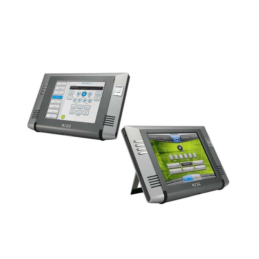
Panels Overview The MVP-7500 (7.5") and MVP-8400 (8.4") Modero Viewpoint Wireless Touch Panels (FIG. 1) are 802.11-based wireless handheld G4 touch panels, pre-installed with an 802.11 Wi-Fi Interface Card to communicate with a NetLinx Master via a standard 802.11b/g Wireless Access Point. -
Page 12: Mvp Specifications
MVP Modero Viewpoint Wireless Touch Panels MVP Specifications The MVP-7500 (FG5965-01) utilizes a 7.5" Color Passive LCD to display a 640 x 480 pixel image with 4096 colors. The MVP-8400 panel (FG5965-02) utilizes an 8.4" Color Active LCD to display an 800 x 600 pixel resolution using 256K colors. - Page 13 Wireless Interface card: Wireless Access Point (such as the NXA-WAP200G). Transmit IR over 20 feet (6.10 m). IR Emitters: Emits a Piezo electric tone (MVP-7500 only). Internal buzzer: One speaker for stereo output (MVP-8400 only). Internal speakers: For use with the intercom feature (MVP-8400 only).
- Page 14 Certifications: • FCC Part 15 Class B and CE Included Accessories: • MVP-BP Power Pack (FG5965-20): 1 with MVP-7500, 2 with MVP-8400 • 80211xCF Wireless Interface Compact Flash card (Type 1) - pre-installed • PS4.4 Power Supply (FG423-44) • Stylus Other AMX Equipment: •...
-
Page 15: Mvp-Bp Power Pack
Overview The MVP-BP Power Pack (FG5965-20) is a rechargeable Lithium-Ion battery used to provide power to the MVP touch panels. One MVP-BP is included with each MVP-7500 touch panel. Two MVP-BPs are included with each MVP-8400 touch panel. FIG. 3... - Page 16 If you are only using one battery, use Battery Slot #1. 4. To replace the battery compartment cover, use the alignment guide holes to align the cover with the edges of the battery compartment, and slide it back into place until it snaps shut. MVP-7500/8400 Modero Viewpoint Wireless Touch Panels...
-
Page 17: Nxa-Cfsp Compact Flash
3. Grasp the bottom rim of the rear housing just above the MVP interface connector, and carefully pull the bottom rim away from the IR Emitter and up, to expose the internal components. 4. Remove the trim from the top rim of the circuit board (FIG. 5). MVP-7500/8400 Modero Viewpoint Wireless Touch Panels... -
Page 18: Removing The Installed Card
Installing the Compact Flash Upgrade Card 1. Discharge any static electricity from your body by touching a grounded metal object and then locate the memory card slot on the main board (A in FIG. 6). MVP-7500/8400 Modero Viewpoint Wireless Touch Panels... - Page 19 6. Insert the new card firmly into the slot opening connector (FIG. 7) until the contact pins are completely inside the card and securely attached to the pin sockets. Any new Compact Flash card upgrade is detected by the panel only after the unit cycles power. MVP-7500/8400 Modero Viewpoint Wireless Touch Panels...
- Page 20 NXA-CFSP Compact Flash MVP-7500/8400 Modero Viewpoint Wireless Touch Panels...
-
Page 21: Wireless Interface Cards
FIG. 8 802.11b Wireless Interface Card The wireless interface card works with 802.11b/g Wireless Access Points, such as the NXA-WAP200G. The NXA-WAP200G uses a default SSID of AMX. Follow your particular WAP’s instruction manual for setup procedures. Specifications 802.11b Wireless Interface Card Specifications Dimensions (HWD): •... -
Page 22: Nxa-Wc80211Gcf 802.11G Wireless Interface Card
The NXA-WC80211GCF incorporates DSSS and OFDM radio technology and operates at ISM frequency bands of 2.4 GHz, while providing data transfer speeds of up to 54Mbps. Other features include: Support for IEEE 802.11b and 802.11g Supports Advanced Encryption Standard (AES) at 128-bit. MVP-7500/8400 Modero Viewpoint Wireless Touch Panels... -
Page 23: Specifications
MVP panels require the use of a cardboard cutout (Mounting Template) to properly position the metal antenna plate onto the inner surface of the unit’s rear plastic housing. The procedures for upgrading a CF card on an MVP is identical for both MVP-7500 and MVP-8400 panels. Specifications... - Page 24 • 802.11g communication: 12 +-1 dBm (6, 9, 12, 18, 24, 36, 48, and 54 Mbps) Wireless LAN Security: • EAP-FAST • EAP-LEAP • EAP-PEAP • EAP-TLS • EAP-TTLS • WEP 64 & 128 • WPA-PSK MVP-7500/8400 Modero Viewpoint Wireless Touch Panels...
-
Page 25: Installing The 802.11G Card And Antenna
Firmware Requirements The NXA-WC80211GCF requires panel firmware versions 5965-01(MVP-7500), and 5965-02 (MVP- 8400). This firmware supports backwards compatibility with 802.11b cards, and security protocols for the NXA-WC80211GCF. -
Page 26: Installing The Nxa-Wc80211Gcf
-shaped opening on the left of the cutout and make sure the antenna wire is located along the left side of the cutout (FIG. 4). FIG. 11 Adhering the antenna plate to the MVP outer housing MVP-7500/8400 Modero Viewpoint Wireless Touch Panels... -
Page 27: Closing And Securing The Mvp Enclosure
Be careful not to pinch the antenna wire in the housing. 6. Use a grounded Phillips-head screwdriver to insert and re-secure the two housing screws removed in Step 1. 7. Insert any available batteries back into the battery compartment. MVP-7500/8400 Modero Viewpoint Wireless Touch Panels... - Page 28 Battery Compartment cover and slide it back towards the metal plate to reinstall the cover. Once the wireless CF card has been installed, be careful not to disconnect or damage the antenna when subsequentally opening the MVP’s housing. MVP-7500/8400 Modero Viewpoint Wireless Touch Panels...
-
Page 29: Configuring Communications
Modero Setup and System Settings AMX Modero panels feature on-board Setup pages. Use the options in the Setup pages to access panel information and make various configuration changes. Accessing the Setup and Protected Setup Pages 1. -
Page 30: Setting The Panel's Device Number
Appendix B - Wireless Technology section on page 183. For more information on utilizing the AMX Certificate Upload Utility in conjunction with the EAP security, refer to the section of the document entitled: Appendix B - Wireless Technology section on page 183. -
Page 31: Configuring A Wireless Network Access
5. Do not alter any of these remaining greyed-out fields in the IP Settings section. Once the panel is rebooted, these values are obtained by the unit and displayed in the DNS fields after power-up. MVP-7500/8400 Modero Viewpoint Wireless Touch Panels... -
Page 32: Wireless Communication Using A Static Ip Address
Security Type (if detectable - such as WEP, OPEN and UNKNOWN) - security protocol enabled on the WAP Signal Strength - None, Poor, Fair, Good, Very Good, and Excellent MAC Address - Unique identification of the transmitting Access Point MVP-7500/8400 Modero Viewpoint Wireless Touch Panels... - Page 33 None) If the panel detects more than 10 WAPs, the Up/Down arrows at the far right side of the page become active (blue) and allow the user to scroll through the list of entries. MVP-7500/8400 Modero Viewpoint Wireless Touch Panels...
-
Page 34: Step 2: Configure The Card's Wireless Security Settings
- Wireless Technology section on page 183 for more information on the other security methods. Once you have set up the wireless card parameters, you must configure the communication parameters for the target Master; see Step 3: Choose a Master Connection Mode section on page 31. MVP-7500/8400 Modero Viewpoint Wireless Touch Panels... -
Page 35: Configuring The Modero's Wireless Card For Unsecured Access To A Wap200G
(Clear Text) Settings dialog (FIG. 19). An Open security method does not utilize any encryption methodology but does require that an SSID (alpha-numeric) be entered. Using this method causes network packets to be sent out as unencrypted text. MVP-7500/8400 Modero Viewpoint Wireless Touch Panels... - Page 36 The card should be given the SSID used by the target WAP. If this field is left blank, the unit will attempt to connect to the first available WAP. By default, all WAP200Gs use AMX as their assigned SSID value.
-
Page 37: Configuring The Modero's Wireless Card For Secured Access To A Wap200G
4. Write down the SSID name, Current Key string value, and panel MAC Address information so you can later enter it into the appropriate WAP dialog fields in order to "sync-up" the secure connection. These values must be identically reproduced on the target WAP. MVP-7500/8400 Modero Viewpoint Wireless Touch Panels... -
Page 38: Manually Set Ssid
The card should be given the SSID used by the target WAP. If this field is left blank, the unit will attempt to connect to the first available WAP. By default, all WAP200Gs use AMX as their assigned SSID value. - Page 39 8. Within this on-screen WEP Passphrase keyboard (FIG. 23), enter a character string or word (such as AMXPanel) and press Done when you have finished. FIG. 23 WEP Passphrase Keyboard MVP-7500/8400 Modero Viewpoint Wireless Touch Panels...
- Page 40 Wireless Access Point. If there is no signal or no IP Address displayed; configuration of your network could be required. Refer to the NXA-WAP200G Instruction Manual for more detailed setup and configuration procedures. MVP-7500/8400 Modero Viewpoint Wireless Touch Panels...
-
Page 41: Configuring Multiple Wireless Moderos To Communicate To A Target Wap200G
NetLinx Studio can be setup to run a Virtual Master where the PC acts as the Master by supplying its own IP Address for communication to the panel. For a PC to establish a USB connection with a Modero panel, it must have the AMX USBLAN driver installed. MVP-7500/8400 Modero Viewpoint Wireless Touch Panels... -
Page 42: Prepare Your Pc For Usb Communication With The Panel
Configuring Communications The AMX USBLAN driver is included with both NetLinx Studio2 and TPDesign4, and can also be downloaded as a stand-alone application from www.amx.com. Prepare your PC for USB communication with the panel If you haven’t already done so, download and install the latest versions of NetLinx Studio2 and TPDesign4 (from www.amx.com), and restart your PC. -
Page 43: Configure A Virtual Netlinx Master Using Netlinx Studio
Configuring Communications ® the panel. It also indicates that the AMX USBLAN driver does not contain a Microsoft digital signature. FIG. 27 USB driver installation popup window 8. Click Yes to proceed with the driver installation. Once the installation is complete, the panel and PC are ready to communicate via USB. - Page 44 The Connection status turns green after a few seconds to indicate an active USB connection to the PC (Virtual Master). If the System Connection icon does not turn green, check the USP connection and communication settings and refresh the system. MVP-7500/8400 Modero Viewpoint Wireless Touch Panels...
-
Page 45: Ethernet
1. Verify the panel has been configured to communicate with the Wireless Access Point and verify the signal strength quality bargraph is On. 2. Launch NetLinx Studio 2.x (default location is Start > Programs > AMX Control Disc > NetLinx Studio 2 > NetLinx Studio 2). - Page 46 13. After the panel powers-up, press and hold the two lower buttons on both sides of the display (for 3 seconds) to continue with the setup process and proceed to the Setup page. 14. Select Protected Setup > System Settings (located on the lower-left) to open the System Settings page (FIG. 30). MVP-7500/8400 Modero Viewpoint Wireless Touch Panels...
- Page 47 By selecting URL, the System Number field becomes read-only (grey) because the panel pulls this value directly from the communicating target Master (virtual or not). A Virtual Master system value can be set within the active AMX software applications such as: NetLinx Studio, TPD4, or IREdit.
-
Page 48: Using G4 Web Control To Interact With A G4 Panel
Refer to the G4 Web Control Settings/G4 Web Control Page section on page 80 for more detailed field information. Verify your NetLinx Master (ME260/64 or NI-Series) has been installed with the latest firmware KIT file from www.amx.com. Refer to your NetLinx Master instruction manual for more detailed information on the use of the new web-based NetLinx Security. - Page 49 19. Press the on-screen Reboot button to save any changes and restart the panel. Verify your NetLinx Master’s IP Address and System Number have been properly entered into the Master Connection section of the System Settings page. MVP-7500/8400 Modero Viewpoint Wireless Touch Panels...
-
Page 50: Using Your Netlinx Master To Control The G4 Panel
If the Master has been previously configured for secured communication, click OK to accept the AMX SSL certificate (if SSL is enabled) and then enter a valid username and password into the fields within the Login dialog. 4. Click OK to enter the information and proceed to the Master’s Manage WebControl Connections window. - Page 51 Wireless Settings page (MVP) FIG. 35 Connection Details dialog 9. If a WebControl password was setup on the G4 WebControl page, a G4 Authentication Session password dialog box appears on the screen within the secondary browser window. MVP-7500/8400 Modero Viewpoint Wireless Touch Panels...
- Page 52 A small circle appears within the on-screen G4 panel page and corresponds to the location of the mouse cursor. A left-mouse click on the computer-displayed panel page equates to an actual touch on the target G4 panel page. MVP-7500/8400 Modero Viewpoint Wireless Touch Panels...
-
Page 53: Upgrading Mvp Firmware
Upgrading MVP Firmware Upgrading MVP Firmware Except for the MVP-KS (Kickstand for MVP Panels), all MVP panels and their accessories have on- board firmware which is upgradeable through the use of the latest NetLinx Studio. The MVP acts as a bridge between the NetLinx Studio program and the installed docking station. -
Page 54: Upgrading The Modero Firmware Via The Usb Port
8. Navigate back to the System Settings page. Step 2: Prepare Studio for communication via the USB port 1. Launch NetLinx Studio 2.x (default location is Start > Programs > AMX Control Disc > NetLinx Studio 2 > NetLinx Studio 2). -
Page 55: Step 3: Confirm And Upgrade The Firmware Via The Usb Port
Upgrading MVP Firmware IP Address of computer (not needed as this is a direct USB connection) FIG. 36 Assigning Communication Settings for a Virtual Master 6. Click the Edit Settings button (on the Communications Settings dialog) to open the Virtual NetLinx Master Settings dialog (FIG. - Page 56 The panel-specific firmware is shown on the right of the listed panel. Download the latest firmware file from www.amx.com and then save the Kit file to your computer. Note that each kit file is intended for download to its corresponding panel.
-
Page 57: Upgrading The Docking Station Firmware Via Usb
Upgrading MVP Firmware 10. Click the Reboot Device checkbox. This causes the touch panel to reboot after the firmware update process is complete. The reboot of the panel can take up 30 seconds after the firmware process has finished. 11. Click Send to begin the transfer. The file transfer progress is indicated on the bottom-right of the dialog (B in FIG. -
Page 58: Step 2: Upgrade The Docking Station Firmware Via Usb
OnLine Tree tab of the Workspace window. The default Modero panel value is 10001. 5. Locate the latest firmware file from the www.amx.com > Tech Center > Downloadable Files > Firmware Files > Modero Panels firmware (MVP Docking Stations: MVP-TDS/WDS) section of the website. - Page 59 Upgrading MVP Firmware Selected Docking Station Firmware file Description field for selected Kit file Firmware download status Device and System values must match the System and Device values listed in the Project Navigator window FIG. 41 Send to NetLinx Device dialog (showing docking station firmware update via USB) Firmware upgrades can not be done directly to the docking station but must be routed through the MVP panel.
- Page 60 Upgrading MVP Firmware Although firmware upgrades can be done over wireless Ethernet; it is recommended that firmware KIT files be transferred over a direct USB connection and only when the panel is connected to a power supply. If battery power or wireless connection fails during a firmware upgrade, the panel flash file system may become corrupted.
-
Page 61: Setup Pages
Setup Pages Setup Pages AMX Modero panels feature on-board Setup pages. Use the options in the Setup pages to access panel information and make various configuration changes. To access the Setup pages, press the two lower external pushbuttons on either side of the panel simultaneously and hold for 3 seconds (FIG. - Page 62 Panel Brightness field. LCD Control: Sets the display brightness and contrast levels of the panel. (MVP-7500 only) • Press the Brightness UP/DN buttons to adjust the brightness level. Range = 0 - 100.
-
Page 63: Navigation Buttons
The custom logo feature allows a user to customize the boot splash screen with a JPEG image. The custom logo will be displayed a short time after the standard AMX logo appears and will be visible until the user pages are loaded. Adding a custom logo to a panel is done by importing an image into the resource manager of the user pages in TPDesign. -
Page 64: Protected Setup Pages
Enter the factory default password (1988) into the password keypad to access this page. FIG. 46 Protected Setup Page showing default values (MVP-7500) FIG. 47 Protected Setup page showing default values (MVP-8400) MVP Modero ViewPoint Touch Panels... - Page 65 System Recovery (Cont.): • Remove User Pages - allows you remove all TPD4 touch panel pages currently on the panel, including the pre-installed AMX Demo pages. This option invokes a Confirmation dialog, prompting you to confirm your selection before removing the panel pages.
-
Page 66: Protected Setup Navigation Buttons
Press to access the Tools menu and select Panel Logs, Panel Statistics, or Connection Utility. FIG. 49 Protected Setup Navigation Buttons (MVP-7500) Closes the Protected Setup page. Press to access the System Settings page where you can configure communication settings for the NetLinx Master and the panel. -
Page 67: Security Settings
Setup Pages Security Settings The Security button on the Protected Setup page has three settings: Standard Security, Secure, and DoD. Each setting has different features for touch panel security: Security Profile Features Standard Security: • Factory default, shipped in this configuration. •... -
Page 68: System Settings Page
Setup Pages For more information on configuring AMX devices for a secure environment, please refer to the guide Security Profiles: Configuring AMX Devices For Installation Into a Secure Environment, available at www.amx.com. System Settings Page The System Settings page (FIG. 51 and FIG. 52) displays sets the NetLinx Master’s communication settings. - Page 69 Setup Pages The elements of this page include: System Settings Page Elements Back: Saves all changes and returns to the previous page. Connection Status icon: The icon in the upper-right corner of each Setup page shows online/offline state of the panel to the master. •...
-
Page 70: Wireless Settings Page
Use the options on the Wireless Settings page (FIG. 53 and FIG. 54) to configure communication settings for the wireless CF card (802.11b/g), and read the device number assigned to the panel. FIG. 53 Wireless Settings Page (MVP-7500) MVP Modero ViewPoint Touch Panels... - Page 71 Setup Pages FIG. 54 Wireless Settings Page (MVP-8400) Features on this page include: Wireless Settings Page Back: Saves all changes and returns to the previous page. Connection Status icon: The icon in the upper-right corner of each Setup page shows online/offline state of the panel to the master.
- Page 72 Setup Pages Wireless Settings Page (Cont.) IP Settings (Cont.) Domain Enter a unique name to the panel for DNS look-up. MAC Address This unique address identifies the wireless Ethernet card in the panel (read-only). IP Settings (Cont.): Active Roaming on When enabled, the device is actively roaming on the channels 1, 6, and 11.
- Page 73 Setup Pages Wireless Settings Page (Cont.) Site Survey: Launches the Site Survey page. The options on this page allow you to detect (“sniff-out”) all WAPs transmitting within range of the panel’s NXA- WC80211GCF Wi-Fi card (this feature is not available with the 802.11b). Data displayed on the Site Survey page is categorized by: - Network Name (SSID) - WAP names - Channel (RF) - channels currently being used by the WAP...
- Page 74 Setup Pages FIG. 55 Wireless Security: Simple Mode Wireless Security: Simple Mode Security Type: This field may be switched between WEP, WPA-PSK, and Open. If WEP is selected, the button to the right may be switched between 64 and 128. •...
- Page 75 (Refer to the EAP-PEAP Settings section on page 72 for details. For information on uploading a certificate file, refer to the AMX Certificate Upload Utility section on page 185.) • EAP-TTLS security is designed for wireless environments where it is necessary to first have a Radius server directly validate the identity of the client (panel) before allowing it access to the network.
-
Page 76: Wireless Settings
Setup Pages Wireless Security: Enterprise Mode (Cont.) Password: Press this field to enter a password for wireless access in the Password keypad. (NOTE: this field is greyed out when selecting EAP-TLS as a Security Type.) Certificate Authority: Press this field to enter the file location for a Certificate Authority certificate in the Certificate Authority (CA) keypad. -
Page 77: Open Settings
• Make sure this setting is the same for all points in your wireless network. • NXA-WAP200Gs use AMX as their default SSID. • If this field is left blank, the panel will attempt to connect to the first available WAP. - Page 78 • The Passphrase generator is case sensitive. Note: This Key generator is unique to Modero panels and does not generate the same keys as non-AMX wireless devices. For example, a Current Key string generated anywhere else will not match those created on Modero panels.
-
Page 79: Wpa-Psk Settings
• Make sure this setting is the same for all points in your wireless network. • NXA-WAP200Gs use AMX as their default SSID. • If this field is left blank, the panel will attempt to connect to the first available WAP. -
Page 80: Eap-Leap Settings
This works in tandem with the Password string which is similar to the password entered to gain access to a secured workstation. Typically, this is in the form of a username such as: jdoe@amx.com. Password: Opens an on-screen keyboard. Enter the network password string specified... -
Page 81: Eap-Fast Settings
This works in tandem with the Password string which is similar to the password entered to gain access to a secured workstation. Typically, this is in the form of a username such as: jdoe@amx.com. Anonymous Identity: Opens an on-screen keyboard. Enter an IT provided alpha-numeric string which (similar to the username) used as the identity, but that does not represent a real user. -
Page 82: Eap-Peap Settings
This works in tandem with the Password string which is similar to the password entered to gain access to a secured workstation. Typically, this is in the form of a username such as: jdoe@amx.com. MVP Modero ViewPoint Touch Panels... - Page 83 Setup Pages EAP-PEAP Settings (Cont.) Password: Opens an on-screen keyboard. Enter the network password string specified for the user entered within the Identity field (used by the panel to identify itself to an Authentication (RADIUS) Server) Note: This information is similar to the password entered to gain access to a secured workstation.
-
Page 84: Eap-Ttls Settings
This works in tandem with the Password string which is similar to the password entered to gain access to a secured workstation. Typically, this is in the form of a username such as: jdoe@amx.com. Anonymous Identity: Opens an on-screen keyboard. Enter an IT provided alpha-numeric string which (similar to the username) used as the identity, but that does not represent a real user. - Page 85 Setup Pages EAP-TTLS Settings (Cont.) Certificate Authority: When pressed, the panel displays an on-screen Certificate Authority (CA) File Location keyboard which allows you to enter the name of the certificate authority file which is used to validate the server certificate. This field is optional.
-
Page 86: Eap-Tls Settings
This works in tandem with the Password string which is similar to the password entered to gain access to a secured workstation. Typically, this is in the form of a username such as: jdoe@amx.com. Certificate Authority: When pressed, the panel displays an on-screen Certificate Authority (CA) File Location keyboard which allows you to enter the name of the certificate authority file which is used to validate the server certificate. -
Page 87: Client Certificate Configuration
First file contains the client certificate, second file not supported not supported contains the private key. Format is: PKCS12 AMX supports the following security certificates PEM (Privacy Enhanced Mail) DER (Distinguished Encoding Rules) PKCS12 (Public Key Cryptography Standard #12) PKCS12 files are frequently generated by Microsoft certificate applications. - Page 88 Setup Pages It is important to note which certificate types are supported by the different certificate fields used on the configuration screens (PEAP, TTLS, and TLS). The following table outlines the firmware fields and their supported certificate types. Certificate Types Supported by the Modero Firmware Configuration Field Name Certificate File Type Supported Certificate Authority field PEM and DER...
-
Page 89: Calibration Page
Setup Pages Calibration Page This page (FIG. 57) allows you to calibrate the touch panel for accurate button selection. FIG. 57 Calibration Page Press and hold the two lower button on both sides of the display for 6 seconds to access the Calibration page (see FIG. -
Page 90: G4 Web Control Settings/G4 Web Control Page
VNC client. Once connected, the client can view and control the panel remotely. The options on the MVP-7500 G4 Web Control Settings page (FIG. 58) and the MVP-8400 Web Control page (FIG. 59) allow you to enable/disable G4 Web Control functionality. - Page 91 Setup Pages Features on this page include: G4 Web Control Page Back: Saves all changes and returns to the previous page. Connection Status icon: The icon in the upper-right corner of each Setup page provides a constant visual indication of current connection status. Note: a Lock appears on the icon if the panel is connected to a secured NetLinx Master.
-
Page 92: Other Settings
The Other Settings button (FIG. 60 and FIG. 61) provides a menu to select the Cache Settings/Cache Setup page, Password Setup page, or SIP Settings page (MVP-8400 only). Select any option to access its page. FIG. 60 Other Settings Menu (MVP-7500) FIG. 61 Other Settings menu (MVP-8400) MVP Modero ViewPoint Touch Panels... -
Page 93: Cache Settings/Cache Setup Page
Setup Pages Cache Settings/Cache Setup Page The Cache Settings page (MVP-7500, FIG. 62) and Cache Setup page (MVP-8400, FIG. 63) configures the allocation of memory for image caching. The G4 graphics engine caches images to decrease load time of previously viewed images. RAM caching is always enabled, and images (both static and dynamic) are stored in the RAM cache as they are viewed. - Page 94 Setup Pages FIG. 63 Cache Setup Page (MVP-8400) The elements of this page include: Cache Settings/Cache Setup Page Elements Back: Saves all changes and returns to the previous page. Connection Status icon: The icon in the upper-right corner of each Setup page shows online/offline state of the panel to the master.
-
Page 95: Setting The Image Cache
Setup Pages Cache Settings/Cache Setup Page Elements (Cont.) RAM Hit Rate The percentage of image requests (static and dynamic) satisfied by accessing the cache. 100 * (# of cache hits) / (# of cache hits + # of cache misses) # of cache hits - the number of times an image was requested that the image was found in the cache. -
Page 96: Password Setup Page
Setup Pages Password Setup Page The options on the Password Setup page enable you to assign the passwords required for users to access the Protected Setup page, and to release the MVP from a MVP-TDS or MVP-WDS docking station (FIG. 64). FIG. -
Page 97: Sip Settings Page (Mvp-8400 Only)
Setup Pages Password Setup Page (Cont.) User Access: Use these buttons to access and modify the user name/password combinations required for removing the panel from a docking station. The number of user access passwords on the panel is limited only by the amount of storage memory available. - Page 98 Setup Pages FIG. 65 SIP Settings Page (MVP-8400 only) Features on this page include: SIP Settings Page Back: Saves all changes and returns to the previous page. Connection Status icon: The icon in the upper-right corner of each Setup page shows online/offline state of the panel to the master.
-
Page 99: Tools
The options on the Panel Connection Logs page (FIG. 68) and the Panel Logs page (FIG. 69) allow you to view and track the connection history of the panel. FIG. 68 Panel Connection Logs (MVP-7500) MVP Modero ViewPoint Touch Panels... -
Page 100: Checking The Panel Connection Logs
Setup Pages FIG. 69 Panel Logs page (MVP-8400) Features on this page include: Panel Logs Page Back: Saves all changes and returns to the previous page. Connection Status icon: The icon in the upper-right corner of each Setup page shows online/offline state of the panel to the master. -
Page 101: Refreshing The Panel Connections Log
Setup Pages Refreshing the Panel Connections Log 1. Press the Tools button in the Protected Setup Navigation Buttons section. This opens the Tools menu. 2. Within the Tools menu, press the Panel Logs button. 3. Push the Refresh button. Clearing the Panel Connections Log 1. -
Page 102: Panel Statistics Page
The options on the Panel Statistics page (FIG. 70 and FIG. 71) allow you to track the connection status for the panel. The Panel Statistics page tracks ICSP messages, Blink messages, Ethernet connection statistics, and Wireless connection statistics. FIG. 70 Panel Statistics Page (MVP-7500) FIG. 71 Panel Statistics page (MVP-8400) MVP Modero ViewPoint Touch Panels... -
Page 103: Checking The Panel Statistics
Setup Pages Features on this page include: Panel Statistics Page Back: Saves all changes and returns to the previous page. Connection Status icon: The icon in the upper-right corner of each Setup page shows online/offline state of the panel to the master. •... -
Page 104: Clearing The Panel Statistics
Setup Pages Clearing the Panel Statistics 1. Press the Tools button in the Protected Setup Navigation Buttons section. This opens the Tools menu. 2. Within the Tools menu, press the Panel Statistics button. 3. Push the Clear button. 4. Confirm your selection. MVP Modero ViewPoint Touch Panels... -
Page 105: Connection Utility Page
While in this page, move around your wireless network coverage area and see if there are any weak points within the spaces between your WAPs FIG. 72 Connection Utility Page (MVP-7500) FIG. 73 Connection Utility Page (MVP-8400) - Page 106 The data rate (in Mbps) at which the panel is currently communicating with the target WAP. Note: Data rates for 802.11b communication are: 1, 2, 5.5, and 11 Mbps. Signal Level (MVP-7500) A bar display showing the current signal strength. Link Quality (MVP-8400)
-
Page 107: Using The Connection Utility
Setup Pages Using the Connection Utility 1. Press the Tools button in the Protected Setup Navigation Buttons section. This opens the Tools menu. 2. Within the Tools menu, press the Connection Utility button. This launches the Connection Utility popup. 3. Move the panel throughout your wireless network, and changes within the utility. The Connection Information notes the IP of the connected master and the IP of your panel. -
Page 108: Information
The Information button (FIG. 74 and FIG. 75) provides a menu to select either the Project Information Page section on page 99 or the Panel Information Page section on page 101. Select either option to access that page. FIG. 74 Information Menu (MVP-7500) FIG. 75 Information Menu (MVP-8400) MVP Modero ViewPoint Touch Panels... -
Page 109: Project Information Page
The Project Information page (FIG. 76 and FIG. 77) displays the project properties of the TPDesign4 project file currently loaded on the panel. FIG. 76 Project Information Page (MVP-7500) FIG. 77 Project Information page (MVP-8400) and corresponding TPD4 project properties tabs... - Page 110 Receivers tab). • For example if you set the AMX IR 38K Port to 7 and then put a button on the panel with a channel code of 5 and a port of 7, it will trigger the IR code in slot 5 of the AMX IR 38K Port.
-
Page 111: Panel Information Page
Setup Pages Panel Information Page The Panel Information page (FIG. 78 and FIG. 79) provides detailed panel information. FIG. 78 Panel Information Page (MVP-7500) FIG. 79 Panel Information Page (MVP-8400) MVP Modero ViewPoint Touch Panels... - Page 112 Setup Pages Features on this page include: Panel Information Page Back: Saves all changes and returns to the previous page. Connection Status icon: The icon in the upper-right corner of each Setup page shows online/offline state of the panel to the master. •...
-
Page 113: Time & Date Setup
NetLinx Master. If the time and/or date on the Master is modified, all connected devices will be updated to reflect the new information. FIG. 80 Time & Date Settings Page (MVP-7500) FIG. 81 Time and Date Setup Page (MVP-8400) MVP touch panels do not have an on-board clock;... - Page 114 Setup Pages Features on this page include: Time & Date Setup Page Back: Saves all changes and returns to the previous page. Connection Status icon: The icon in the upper-right corner of each Setup page shows online/offline state of the panel to the master. •...
-
Page 115: Audio Settings
The MVP-8400 provides an Audio Settings page (FIG. 82 and FIG. 83) with options that allow you to adjust volume levels, set intercom sound and microphone levels, and set panel sounds. FIG. 82 Audio Settings Page (MVP-7500) FIG. 83 Audio Settings Page (MVP-8400) -
Page 116: Wav Files - Supported Sample Rates
Setup Pages Volume Page (Cont.) Master Volume: This section allows you to alter the current master volume level: • Use the UP/DN buttons to adjust the volume level (range = 0 - 100). • The Master Volume bargraph indicates the current volume level. •... -
Page 117: Battery Settings/Batteries
Setup Pages Battery Settings/Batteries The options on the MVP-7500 Battery Settings page (FIG. 84) and the MVP-8400 Batteries page (FIG. 85) allow you to set power warning preferences, monitor battery status information, and adjust the display times for battery warnings. This page is populated with information from MVP-BP batteries in the panel, as well as batteries in a connected MVP-TDS/WDS docking station. - Page 118 Setup Pages Features on this page include: Batteries Page Back: Saves all changes and returns to the previous page. Connection Status icon: The icon in the upper-right corner of each Setup page shows online/offline state of the panel to the master. •...
-
Page 119: Eap Security & Server Certificates - Overview
Setup Pages Batteries Page (Cont.) Battery Status: • The Combined Charge Status bargraph indicates the combined power charge available from batteries installed in the panel. • The Battery One Charge Status bargraph indicates the power charge available on the Slot 1 battery (in the panel). •... - Page 120 Setup Pages If a server certificate is used, it should first be downloaded into the panel and the Certificate Authority field should then be set to the name of that certificate file. No file path should be used for this setting as all certificates are stored in a specific directory that the user cannot control or change.
-
Page 121: Programming
= 1 - 50 ASCII characters. Name of the popup page. popup group name = 1 - 50 ASCII characters. Name of the popup group. Example: SEND_COMMAND Panel,"'@APG-Popup1;Group1'" Adds the popup page ’Popup1’ to the popup group ’Group1’. MVP-7500/8400 Modero Viewpoint Wireless Touch Panels... - Page 122 = 1 - 50 ASCII characters. Name of the page the popup is displayed Example: SEND_COMMAND Panel,"'@PHP-Popup1;75,0'" Sets the Popup1 hide effect x-coordinate value to 75 and the y-coordinate value to 0. MVP-7500/8400 Modero Viewpoint Wireless Touch Panels...
- Page 123 Toggles the popup page ’Popup1’ on the ’Main’ page from one state to another (On/Off). Example 2: SEND_COMMAND Panel,"'@PPG-Popup1'" Toggles the popup page ’Popup1’ on the current page from one state to another (On/Off). MVP-7500/8400 Modero Viewpoint Wireless Touch Panels...
- Page 124 = 1 - 50 ASCII characters. Name of the popup page. timeout = Timeout duration in 1/10ths of a second. Example: SEND_COMMAND Panel,"'@PPT-Popup1;30'" Sets the popup page ’Popup1’ to timeout within 3 seconds. MVP-7500/8400 Modero Viewpoint Wireless Touch Panels...
- Page 125 Flip to a specified page. Syntax: "'PAGE-<page name>'" Variable: page name = 1 - 50 ASCII characters. Name of the page the popup is displayed On. Example: SEND_COMMAND Panel,"'PAGE-Page1'" Flips to page1. MVP-7500/8400 Modero Viewpoint Wireless Touch Panels...
- Page 126 = 1 - 50 ASCII characters. Name of the page the popup is displayed On. Example: SEND_COMMAND Panel,"'PPON-Popup1; Main'" Activates the popup page ’Popup1’ on the Main page. Example 2: SEND_COMMAND Panel,"'PPON-Popup1'" Activates the popup page ’Popup1’ on the current page. MVP-7500/8400 Modero Viewpoint Wireless Touch Panels...
-
Page 127: Programming Numbers
Lime Medium Lime Dark Lime Very Dark Lime Very Light Green Light Green Green Medium Green Dark Green Very Dark Green Very Light Mint Light Mint Mint Medium Mint Dark Mint Very Dark Mint MVP-7500/8400 Modero Viewpoint Wireless Touch Panels... - Page 128 Very Light Magenta Light Magenta Magenta Medium Magenta Dark Magenta Very Dark Magenta Very Light Pink Light Pink Pink Medium Pink Dark Pink Very Dark Pink White Grey1 Grey3 Grey5 Grey7 Grey9 Grey4 Grey6 MVP-7500/8400 Modero Viewpoint Wireless Touch Panels...
-
Page 129: Font Styles And Id Numbers
32 - Variable Fonts start at 32. You must import fonts into a TPDesign4 project file. The font ID numbers are assigned by TPDesign4. These values are also listed in the Generate Programmer’s Report. MVP-7500/8400 Modero Viewpoint Wireless Touch Panels... -
Page 130: Border Styles And Programming Numbers
Cursor Right with Hole Circle 75 Custom Frame Circle 85 Diamond 15 Circle 95 Diamond 25 Circle 105 Diamond 35 Circle 115 Diamond 45 Circle 125 Diamond 55 Circle 135 Diamond 65 Circle 145 Diamond 75 MVP-7500/8400 Modero Viewpoint Wireless Touch Panels... - Page 131 Menu Right Rounded 55 Menu Bottom Rounded 25 Menu Right Rounded 65 Menu Bottom Rounded 35 Menu Right Rounded 75 Menu Bottom Rounded 45 Menu Right Rounded 85 Menu Bottom Rounded 55 Menu Right Rounded 95 MVP-7500/8400 Modero Viewpoint Wireless Touch Panels...
-
Page 132: Button Commands
= Beginning of button state (0= current state). end state = End of button state. time = In 1/10 second intervals. Example: SEND_COMMAND Panel,"'^ANI-500,1,25,100'" Runs a button animation at text range 500 from state 1 to state 25 for 10 second. MVP-7500/8400 Modero Viewpoint Wireless Touch Panels... - Page 133 1 = Off state and 2 = On state). unicode text = 1 - 50 ASCII characters. Unicode characters must be entered in Hex format. Example: SEND_COMMAND Panel,"'^BAU-520,1,00770062'" Appends Unicode text '00770062' to the button’s OFF state. MVP-7500/8400 Modero Viewpoint Wireless Touch Panels...
- Page 134 = Refer to theRGB Values for all 88 Basic Colors table on page 117 for more information. Example: SEND_COMMAND Panel,"'^BCT-500.504&510,1,12'" Sets the Off state border color to 12 (Yellow). Colors can be set by Color Numbers, Color name, R,G,B,alpha colors (RRGGBBAA) and R, G & B colors values (RRGGBB). MVP-7500/8400 Modero Viewpoint Wireless Touch Panels...
- Page 135 = Refer to theText Area Input Masking section on page 156 for character types. Example: SEND_COMMAND Panel,"'^BIM-500,AAAAAAAAAA'" Sets the input mask to ten ’A’ characters, that are required, to either a letter or digit (entry is required). MVP-7500/8400 Modero Viewpoint Wireless Touch Panels...
- Page 136 WW - Word wrap on/off Example: SEND_COMMAND Panel,"'^BMC-425,1,1,500,1,BR'" SEND_COMMAND Panel,"'^BMC-425,1,1,500,1,%BR'" Copies the OFF state border of button with a variable text address of 500 onto the OFF state border of button with a variable text address of 425. MVP-7500/8400 Modero Viewpoint Wireless Touch Panels...
- Page 137 BUT the 0 (zero) is absolute and followed by ’,<left>,<top>’ ’%JI<alignment of icon 0-9>’ = As shown the above telephone keypad alignment chart, BUT the 0 (zero) is absolute and followed by ’,<left>,<top>’ MVP-7500/8400 Modero Viewpoint Wireless Touch Panels...
- Page 138 ’%VN<network name>’ = Set network connection name. ’%VP<password>’ = Set the network connection password. Example: SEND_COMMAND Panel,"'^BMF-500,1,%B10%CFRed%CB Blue %CTBlack%Ptest.png'" Sets the button OFF state as well as the Border, Fill Color, Border Color, Text Color, and Bitmap. MVP-7500/8400 Modero Viewpoint Wireless Touch Panels...
- Page 139 "'^BNC-<vt addr range>,<command value>'" TakeNote Variable: annotations. variable text address range = 1 - 4000. command value = (0= clear, 1= clear all). Example: SEND_COMMAND Panel,"'^BNC-973,0'" Clears the annotation of the TakeNote button with variable text 973. MVP-7500/8400 Modero Viewpoint Wireless Touch Panels...
- Page 140 = 0 (invisible) - 255 (opaque). Example: SEND_COMMAND Panel,"'^BOP-500.504&510.515,1,200'" Example 2: SEND_COMMAND Panel,"'^BOP-500.504&510.515,1,#C8'" Both examples set the opacity of the buttons with the variable text range of 500-504 and 510-515 to 200. MVP-7500/8400 Modero Viewpoint Wireless Touch Panels...
- Page 141 Sets the border by number (#10) to those buttons with the variable text range of 500-504 & 510-515. SEND_COMMAND Panel,"'^BOR-500.504&510,AMX Elite -M'" Sets the border by name (AMX Elite) to those buttons with the variable text range of 500-504 & 510-515. The border style is available through the TPDesign4 border-style drop-down list. Refer to theTPD4 Border Styles by Name table on page 120 for more information.
- Page 142 1 = Off state and 2 = On state). sound name = (blank - sound cleared, not matched - button sound not changed). Example: SEND_COMMAND Panel,"'^BSO-500,1&2,music.wav'" Assigns the sound 'music.wav' to the button Off/On states. MVP-7500/8400 Modero Viewpoint Wireless Touch Panels...
- Page 143 = 1 - 256 for multi-state buttons (0 = All states, for General buttons 1 = Off state and 2 = On state). word wrap = (0=Off and 1=On). Default is Off. Example: SEND_COMMAND Panel,"'^BWW-500,1,1'" Sets the word wrap on for the button’s Off state. MVP-7500/8400 Modero Viewpoint Wireless Touch Panels...
- Page 144 = 1 - 4000. variable text command value = (0= disable, 1= enable) range. Example: SEND_COMMAND Panel,"'^ENA-500.504&510.515,0'" Disables button pushes on buttons with variable text range 500-504 & 510-515. MVP-7500/8400 Modero Viewpoint Wireless Touch Panels...
- Page 145 2 = Invert vertical axis 3 = Invert both axis locations For a bargraph 1 = Invert , 0 = Non Invert Example: SEND_COMMAND Panel,"'^GIV-500,3'" Inverts the joystick axis origin to the bottom right corner. MVP-7500/8400 Modero Viewpoint Wireless Touch Panels...
- Page 146 = 1 - 4000. color value = Refer to theRGB Values for all 88 Basic Colors table on page 117. Example: SEND_COMMAND Panel,"'^GSC-500,12'" Changes the bargraph or joystick slider color to Yellow. MVP-7500/8400 Modero Viewpoint Wireless Touch Panels...
- Page 147 = 1/10th of a second. offTime = 1/10th of a second. Example: SEND_COMMAND Panel,"'^IRM-10,5, 20, 10'" Sets the port 10 IR channel 5 on time to 1 second and off time to 2 seconds. MVP-7500/8400 Modero Viewpoint Wireless Touch Panels...
- Page 148 = Value of 1 - 9 corresponds to the following locations: Zero can be used for an absolute position Example: SEND_COMMAND Panel,"'^JSI-500.504&510.515,1&2,1'" Sets the Off/On state icon alignment to upper left corner for those buttons with variable text range of 500-504 & 510-515. MVP-7500/8400 Modero Viewpoint Wireless Touch Panels...
- Page 149 Variable: variable text variable text address range = 1 - 4000. range. command value = (0= hide, 1= show). Example: SEND_COMMAND Panel,"'^SHO-500.504&510.515,0'" Hides buttons with variable text address range 500-504 & 510-515. MVP-7500/8400 Modero Viewpoint Wireless Touch Panels...
- Page 150 Sets the text effect to Soft Drop Shadow 3 for the button with variable text range 500-504 and 510-515. Syntax: ^TOP Enable/disable ^TOP-<0=disable output,1=enable output> SEND strings sent Enable/disable send strings sent to master when PRESS/RELEASE happens: to the master. Press,564,219 Release,445,224 MVP-7500/8400 Modero Viewpoint Wireless Touch Panels...
-
Page 151: Miscellaneous Mvp Strings Back To The Master
• This string can be disabled from within the firmware setup pages. This is sent to the target Master when the MVP is docked. dock • This string can be disabled from within the firmware setup pages. MVP-7500/8400 Modero Viewpoint Wireless Touch Panels... -
Page 152: Mvp Panel Lock Passcode Commands
Sets a new user name as "Manager" and the password to "undock". Example 2: SEND_COMMAND Panel,"'^LPS-Manager,test'" Changes the given user name password to "test". Refer to thePassword Setup Page section on page 104 for more information. MVP-7500/8400 Modero Viewpoint Wireless Touch Panels... -
Page 153: Text Effects Names
• Soft Drop Shadow 4 with outline • Soft Drop Shadow 5 with outline • Soft Drop Shadow 6 with outline • Soft Drop Shadow 7 with outline • Soft Drop Shadow 8 with outline MVP-7500/8400 Modero Viewpoint Wireless Touch Panels... -
Page 154: Button Query Commands
(this is not encoded size) slong value3 index of first character (usually 1 or same as optional index string text the text from the button text length (string encode) button text length MVP-7500/8400 Modero Viewpoint Wireless Touch Panels... - Page 155 The result sent to the Master would be: ButtonGet Id = 529 Type = 1011 Flag = 0 VALUE1 = 1 VALUE2 = 9 VALUE3 = 0 TEXT = #222222FF TEXT LENGTH = 9 MVP-7500/8400 Modero Viewpoint Wireless Touch Panels...
- Page 156 Gets the button 'OFF state' text color information. The result sent to Master would be: ButtonGet Id = 529 Type = 1013 Flag = 0 VALUE1 = 1 VALUE2 = 9 VALUE3 = 0 TEXT = #FFFFFEFF TEXT LENGTH = 9 MVP-7500/8400 Modero Viewpoint Wireless Touch Panels...
- Page 157 Gets the button 'OFF state' opacity information. The result sent to the Master would be: ButtonGet Id = 529 Type = 1015 Flag = 0 VALUE1 = 1 VALUE2 = 200 VALUE3 = 0 TEXT = TEXT LENGTH = 0 MVP-7500/8400 Modero Viewpoint Wireless Touch Panels...
- Page 158 Flag = 0 VALUE1 = 1 VALUE2 = 22 VALUE3 = 0 TEXT = Double Bevel Raised -L TEXT LENGTH = 22 Returned in Custom event. ?BRT Get the current Value1=panel brightness value panel brightness. MVP-7500/8400 Modero Viewpoint Wireless Touch Panels...
- Page 159 TEXT LENGTH = 0 Returned in Custom event. ?CHR Get the charging Value1=status(0=not charging,1=charging) status. Value2=current (combined) battery level Returned in Custom event. ?FBC Get the frame Value1=CRC32 calculated on the panel's frame buffer buffer CRC. MVP-7500/8400 Modero Viewpoint Wireless Touch Panels...
- Page 160 Gets the button 'OFF state' icon index information. The result sent to the Master would be: ButtonGet Id = 529 Type = 1003 Flag = 0 VALUE1 = 2 VALUE2 = 12 VALUE3 = 0 TEXT = TEXT LENGTH = 0 MVP-7500/8400 Modero Viewpoint Wireless Touch Panels...
- Page 161 Gets the button 'OFF state' icon justification information. The result sent to the Master would be: ButtonGet Id = 529 Type = 1006 Flag = 0 VALUE1 = 1 VALUE2 = 6 VALUE3 = 0 TEXT = TEXT LENGTH = 0 MVP-7500/8400 Modero Viewpoint Wireless Touch Panels...
- Page 162 <Message>Connected to (Sys=303) Master cjc-master (URL Mode)</ Message> </Log> </PanelLogs> Returned in Custom event. ?MCO Get the Value1=mic out level microphone output level. Returned in Custom event ?MUT Get the mute Value1=button state(0=off, 1=on) value. MVP-7500/8400 Modero Viewpoint Wireless Touch Panels...
- Page 163 <Total><Rx>11</Rx><Proc>11</Proc><Drop>0</Drop></Total> <Rolling><Rx>11</Rx><Proc>11</Proc><Drop>0</Drop></Rolling> </Icsp> <Blink> <Total><Rx>3</Rx><Miss>0</Miss></Total> <Rolling><Rx>3</Rx><Miss>0</Miss></Rolling> </Blink> <Ethernet> <RxPackets>53063571</RxPackets><RxErrors>0</RxErrors> <RxDrops>0</RxDrops><RxOverRuns>0</RxOverRuns><RxFrames>63</ RxFrames> <TxPackets>17842136</TxPackets><TxErrors>0</ TxErrors><TxDrops>0</TxDrops> <TxOverRuns>0</TxOverRuns><TxCarriers>0</TxCarriers> <Collisions>0</Collisions><TxQueueLen>100</TxQueueLen> <RxBytes>292901735</RxBytes><TxBytes>1182103211</TxBytes> </Ethernet> <Wireless> <Mode>Managed</Mode><Frequenc Returned in Custom event. ?STO Get the shutdown Value1=shutdown timeout value (in minutes) timeout value. MVP-7500/8400 Modero Viewpoint Wireless Touch Panels...
- Page 164 The result sent to the Master would be: ButtonGet Id = 529 Type = 1008 Flag = 0 VALUE1 = 1 VALUE2 = 18 VALUE3 = 0 TEXT = Hard Drop Shadow 3 TEXT LENGTH = 18 MVP-7500/8400 Modero Viewpoint Wireless Touch Panels...
-
Page 165: Panel Runtime Operations
Outputs a beep of duration 1 beep even if beep is Off. Syntax: ADBEEP Output a double "'ADBEEP'" beep even if beep Example: is Off. SEND COMMAND Panel,"'ADBEEP'" Outputs a double beep even if beep is Off. MVP-7500/8400 Modero Viewpoint Wireless Touch Panels... - Page 166 = 1 - 50 ASCII characters. prompt text = 1 - 50 ASCII characters. Example: SEND COMMAND Panel,"'@AKP-12345678;ENTER PASSWORD'" Pops up the Keypad and initializes the text string '12345678' with prompt text ’ENTER PASSWORD’. MVP-7500/8400 Modero Viewpoint Wireless Touch Panels...
- Page 167 = 1 - 50 ASCII characters. prompt text = 1 - 50 ASCII characters. Example: SEND COMMAND Panel,"'@EKP-33333333;Enter Password'" Pops up the Keypad and initializes the text string '33333333' with prompt text 'Enter Password'. MVP-7500/8400 Modero Viewpoint Wireless Touch Panels...
- Page 168 Forces the panel into screen saver mode. Syntax: @SOU Play a sound file. "'@SOU-<sound name>'" Variables: sound name = Name of the sound file. Supported sound file formats are: WAV & MP3. Example: SEND COMMAND Panel,"'@SOU-Music.wav'" Plays the 'Music.wav' file. MVP-7500/8400 Modero Viewpoint Wireless Touch Panels...
- Page 169 Example: keyboard. SEND COMMAND Panel,"'@VKB'" Pops-up the virtual keyboard. Syntax: WAKE Force the panel "'WAKE'" out of screen Example: saver mode. SEND COMMAND Panel,"'WAKE'" Forces the panel out of the screen saver mode. MVP-7500/8400 Modero Viewpoint Wireless Touch Panels...
-
Page 170: Input Commands
ASCII character set. application. Syntax: "'^VKS-<string>'" Variable: string = Only 1 string per command/only one stroke per command. Example: SEND COMMAND Panel,"'^VKS-'8" Sends out the keystroke 'backspace' to the G4 application. MVP-7500/8400 Modero Viewpoint Wireless Touch Panels... -
Page 171: Embedded Codes
($9A) Print Screen ($9B) SYSRQ ($9C) ($9D) Windows ($9E) Menu ($9F) Up Arrow ($A0) Down Arrow ($A1) Left Arrow ($A2) Right Arrow ($C0) CTRL key up ($C1) ALT key up ($C2) Shift key up MVP-7500/8400 Modero Viewpoint Wireless Touch Panels... -
Page 172: Panel Setup Commands
Resets the protected Setup page password to ‘1988’. Syntax: ^VOL Set the panel "'^VOL-<volume level>'" volume. Variable: volume level = 0 - 100. 100 is maximum volume setting. Example: SEND_COMMAND Panel,"'^VOL-50'" Set the panel volume to 50. MVP-7500/8400 Modero Viewpoint Wireless Touch Panels... -
Page 173: Dynamic Image Commands
Variable: given resource. resource name = 1 - 50 ASCII characters. refresh rate = Measured in seconds. Example: SEND_COMMAND Panel,"'^RSR-Sports_Image,5'" Sets the refresh rate to 5 seconds for the given resource (’Sports_Image’). MVP-7500/8400 Modero Viewpoint Wireless Touch Panels... - Page 174 SEND_COMMAND Panel,"'^RAF-New Image,%P0%HAMX.COM%ALab/ Test_file%Ftest.jpg'" Adds a new resource. The resource name is ’New Image’, %P (protocol) is an HTTP, %H (host name) is AMX.COM, %A (file path) is Lab/Test file, and %F (file name) is test.jpg. MVP-7500/8400 Modero Viewpoint Wireless Touch Panels...
-
Page 175: Intercom Commands
TP1, "^ICS-192.168.0.3,9000,9002,0" send_command TP2, "^ICS-192.168.0.4,9002,9000,1" Intercom end. This terminates an intercom call/connection. ^ICE' Intercom end. Syntax: SEND_COMMAND <DEV>,"'^ICE'" Variables: None Example: SEND_COMMAND TP1,"'^ICE'" SEND_COMMAND TP2,"'^ICE'" Terminates an intercom call between two panels. MVP-7500/8400 Modero Viewpoint Wireless Touch Panels... - Page 176 0 - unmuted muted (1) or unmuted (0). At 1 - muted the start of each Example: call the SEND_COMMAND Panel, “^ICM-MUTEMIC,1” microphone starts Sets the microphone to muted. out unmuted. MVP-7500/8400 Modero Viewpoint Wireless Touch Panels...
-
Page 177: Sip Commands
= The identifying number of the connection. available connections used state = IDLE, HOLD, or CONNECTED to manage calls. extn = The local extension of this panel (see Example) Example: SEND_COMMAND Panel,"'^PHN-LINESTATE, 1, IDLE, 2, CONNECTED, SIP, <extn>'" MVP-7500/8400 Modero Viewpoint Wireless Touch Panels... - Page 178 Enables (1) or disables (0) the auto-answer feature on the phone. ^PHN- AUTOANSWER Syntax: Enables or "’^PHN-AUTOANSWER, <state>’" disables the Variable: auto-answer feature of the state = 0 (Disable) or 1 (Enable) phone. Example: SEND_COMMAND Panel,"'^PHN-AUTOANSWER, 1'" Enables the auto-answer feature. MVP-7500/8400 Modero Viewpoint Wireless Touch Panels...
- Page 179 = 0 (Disable) or 1 (Enable) Example: SEND_COMMAND Panel,"'^PHN-PRIVACY, 1'" Enables the privacy feature. The panel responds with the ^PHN-PRIVACY, <state> message. ?PHN-PRIVACY Queries the state Syntax: of the privacy "’?PHN-PRIVACY’" feature. Example: SEND_COMMAND Panel,"'?PHN-PRIVACY'" MVP-7500/8400 Modero Viewpoint Wireless Touch Panels...
- Page 180 = The port for the proxy server proxy server. Example: SEND_COMMAND Panel,"’^PHN-SETUP-PORT, 5060’" Syntax: ^PHN-SETUP- PROXYADDR "’^PHN-SETUP-PROXYADDR, <IP>’" Sets the IP Variable: address for the IP = The IP address for the proxy server proxy server. Example: SEND_COMMAND Panel,"’^PHN-SETUP-PROXYADDR, 192.168.223.111’" MVP-7500/8400 Modero Viewpoint Wireless Touch Panels...
- Page 181 STUN server. Example: SEND_COMMAND Panel,"’^PHN-SETUP-STUNADDR, 192.168.223.111’" Syntax: ^PHN-SETUP- USERNAME "’^PHN-SETUP-USERNAME, <username>’" Sets the user Variable: name for username = The user name (usually the phone extension) authentication with the proxy Example: server. SEND_COMMAND Panel,"’^PHN-SETUP-USERNAME, 6003’" MVP-7500/8400 Modero Viewpoint Wireless Touch Panels...
- Page 182 Programming MVP-7500/8400 Modero Viewpoint Wireless Touch Panels...
-
Page 183: Panel Calibration
Modero panels are factory setup with specific demo touch panel pages. The first splash screen that appears indicates the panel is receiving power, beginning to load firmware, and preparing to display the default touch panel pages. When the panel is ready, the AMX Splash Screen is replaced by the Initial Panel Page (FIG. 87). -
Page 184: Testing Your Calibration
If the protective plastic film on the LCD is not removed, the panel may not respond properly to touch points on the LCD nor allow proper screen calibration. 4. Exit this Calibration Test page by pressing the Back button to return to the Protected Setup page. MVP-7500/8400 Modero Viewpoint Wireless Touch Panels... -
Page 185: If Calibration Is Not Working
Panel Calibration If Calibration Is Not Working Cycling power to the panel should provide a baseline calibration for the particular touch panel. Re- calibrate the panel. MVP-7500/8400 Modero Viewpoint Wireless Touch Panels... - Page 186 Panel Calibration MVP-7500/8400 Modero Viewpoint Wireless Touch Panels...
-
Page 187: Appendix A: Text Formatting
Example Format Display $A out of $R 32 out of 100 $A of 0 - $R 32 of 0 - 100 $V of $L - $H 532 of 500 - 600 MVP-7500/8400 Modero Viewpoint Wireless Touch Panels... -
Page 188: Text Area Input Masking
Any character or a space (entry optional) The number of the above characters used determines the length of the input masking box. Example: 0000 requires an entry, requires digits to be used, and allows only 4 characters to be entered/used. MVP-7500/8400 Modero Viewpoint Wireless Touch Panels... -
Page 189: Input Mask Ranges
For example, \A is displayed just as the letter A. To define one of the following characters as a literal character, precede that character with a back-slash. Text entry operation using Input Masks. MVP-7500/8400 Modero Viewpoint Wireless Touch Panels... -
Page 190: Input Mask Output Examples
Hour [1|12]{:} Any value from 1 to 12 Minute/Second [0|59]{:} Any value from 0 to 59 Frames [0|29]{:} Any value from 0 to 29 Phone Numbers (999) 000-0000 (555) 555-5555 Zip Code 00000-9999 75082-4567 MVP-7500/8400 Modero Viewpoint Wireless Touch Panels... -
Page 191: Url Resources
This URL indicates that the protocol in use is http (HyperText Transport Protocol) and that the information resides on a host machine named www.amx.com. The image on that host machine is given an assignment (by the program) name of company-info-home.asp (Active Server Page). - Page 192 Appendix A: Text Formatting MVP-7500/8400 Modero Viewpoint Wireless Touch Panels...
-
Page 193: Appendix B - Wireless Technology
Only devices with common WEP settings will be able to communicate. Similarly, if one device has WEP enabled and another doesn't, they won't be able to talk to each other. MVP-7500/8400 Modero Viewpoint Wireless Touch Panels... -
Page 194: Terminology
The certificate authority (CA) is a trusted external third party which "signs" or validates the certificate. When a certificate has been signed, it gains some cryptographic properties. AMX supports the following security certificates within three different formats: - PEM (Privacy Enhanced Mail) - Page 195 802.1x, TKIP and MIC. Within the WPA specifications the RC4 cipher engine was maintained from WEP. RC4 is widely used in SSL (Secure Socket Layer) to protect internet traffic. FIG. 91 WPA Overview MVP-7500/8400 Modero Viewpoint Wireless Touch Panels...
- Page 196 With the RC4 released to the general public the IEEE implemented the Advanced Encryption Standard (AES) as the cipher engine for 802.11i, which the Wi-Fi Alliance has branded as WPA2. FIG. 92 WPA2 Overview MVP-7500/8400 Modero Viewpoint Wireless Touch Panels...
-
Page 197: Eap Authentication
• Susceptible to MS-CHAP and deployment dictionary • Fixed Passwords MS-CHAPv2 attacks • One-time passwords authentication protocols (tokens) EAP-FAST • Certificates • N/A • N/A • N/A • Fixed Passwords • One-time passwords (tokens) MVP-7500/8400 Modero Viewpoint Wireless Touch Panels... -
Page 198: Eap Communication Overview
WAP completes the process for allowing LAN Access to the panel (possibly a restricted access based on attributes that came back from the RADIUS server). As an example, the WAP might switch the panel to a particular VLAN or install a set of firewall rules. MVP-7500/8400 Modero Viewpoint Wireless Touch Panels... -
Page 199: Amx Certificate Upload Utility
Step 1: Setup the Panel and PC for USB Communication 1. If you do not currently have the latest version of TPDesign4, navigate to www.amx.com > Tech Center > Downloadable Files > Application Files > NetLinx Design Tools section of the website and locate the AMX USB Driver executable (AMX USBLAN Setup exe). -
Page 200: Step 2: Confirm The Installation Of The Usb Driver On The Pc
Step 2: Confirm the Installation of the USB Driver on the PC The first time each AMX touch panel is connected to the PC it is detected as a new hardware device and the USBLAN driver becomes associated with it (panel specific). Each time thereafter the panel is "recognized"... -
Page 201: How To Upload A Certificate File
Confirm the new USB entry shows up in the list as: 10.XX.XX.1. How to Upload a Certificate File 1. Install the latest AMX USB LAN LINK driver onto your computer by installing the latest versions of either TPDesign4 or NetLinx Studio2. This USB driver prepares your computer to properly communicate with a directly connected G4 touch panel (MVP/CV7/CV10). - Page 202 13. When you are ready to send the certificate file to the selected panels, click the Send button to initiate the upload. Once the Status field for each entry reads Done, your upload was successfully completed. MVP-7500/8400 Modero Viewpoint Wireless Touch Panels...
- Page 203 Appendix B - Wireless Technology MVP-7500/8400 Modero Viewpoint Wireless Touch Panels...
- Page 204 Appendix B - Wireless Technology MVP-7500/8400 Modero Viewpoint Wireless Touch Panels...
-
Page 205: Appendix C: Troubleshooting
To keep the batteries from being damaged (from operating at too low a level), the firmware places them into a protected state. The panel must have the latest firmware (if it doesn’t, the firmware can be found at amx.com, in the Dealers/Tech Center > Firmware Files.> Modero). -
Page 206: Modero Panel Isn't Appearing In The Online Tree Tab
When connecting to a NetLinx Master controller via TCP/IP, the program will first try to ping the controller before attempting a connection. Pinging a device is relatively fast and will determine if the device is off-line, or if the TCP/IP address that was entered was incorrect. MVP-7500/8400 Modero Viewpoint Wireless Touch Panels... -
Page 207: Only One Modero Panel In My System Shows Up
Compact Flash. Panel will not boot, or gets stuck on "AMX" splash screen. Other problems also started after downloading to a new panel or a panel with a TPD4 file that takes up a considerable amount of the available Compact Flash. - Page 208 Appendix C: Troubleshooting MVP-7500/8400 Modero Viewpoint Wireless Touch Panels...
- Page 209 Appendix C: Troubleshooting MVP-7500/8400 Modero Viewpoint Wireless Touch Panels...
- Page 210 It’s Your World - Take Control™ 3000 RESEARCH DRIVE, RICHARDSON, TX 75082 USA • 800.222.0193 • 469.624.8000 • 469-624-7153 fax • 800.932.6993 technical support • www.amx.com...
Need help?
Do you have a question about the MVP-7500 and is the answer not in the manual?
Questions and answers