AMX Modero ViewPoint MVP-8400 Operation/Reference Manual
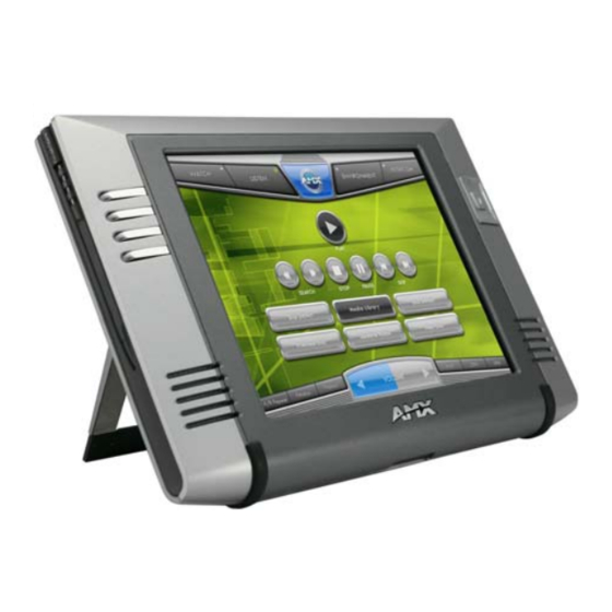
7.5" & 8.4” touch panels
Hide thumbs
Also See for Modero ViewPoint MVP-8400:
- Quick start manual (2 pages) ,
- Datasheet (2 pages) ,
- Dimension manual (1 page)

Related Manuals for AMX Modero ViewPoint MVP-8400


Summary of Contents for AMX Modero ViewPoint MVP-8400
- Page 1 Operation/Reference Guide MVP-7500/8400 ® ® 7.5" & 8.4” Modero ViewPoint Touch Panels Touch Panels L a s t R e v i s e d : 4 /5 / 2 0 1 1...
- Page 2 AMX is not responsible for products returned without a valid RMA number. AMX is not liable for any damages caused by its products or for the failure of its products to perform. This includes any lost profits, lost savings, incidental damages, or consequential damages.
- Page 3 LICENSE GRANT. AMX grants to Licensee the non-exclusive right to use the AMX Software in the manner described in this License. The AMX Software is licensed, not sold. This license does not grant Licensee the right to create derivative works of the AMX Software.
-
Page 5: Table Of Contents
Table of Contents MVP Modero Viewpoint Wireless Touch Panels ...1 Overview ... 1 MVP Specifications ... 2 MVP-BP Power Pack ...5 Overview ... 5 MVP-BP Specifications ... 5 Installing MVP-BP Batteries ... 5 NXA-CFSP Compact Flash ...7 Overview ... 7 Compact Flash Card - Security ... - Page 6 Table of Contents Using the Site Survey tool ... 22 Step 2: Configure the Card’s Wireless Security Settings ... 24 Configuring the Modero’s wireless card for unsecured access to a WAP200G ... 25 Configuring the Modero’s wireless card for secured access to a WAP200G ... 27 Automatically set SSID ...
- Page 7 EAP-TTLS Settings... 74 EAP-TLS Settings... 76 Client certificate configuration... 77 Calibration Page... 79 G4 Web Control Settings/G4 Web Control Page ... 80 Other Settings... 82 Cache Settings/Cache Setup Page ... 83 Setting the image cache... 85 Clearing the image cache ... 85 Checking image cache status ...
- Page 8 Table of Contents @PHP ... 112 @PHT ... 113 @PPA ... 113 @PPF... 113 @PPG ... 113 @PPK ... 114 @PPM... 114 @PPN ... 114 @PPT... 115 @PPX ... 115 @PSE ... 115 @PSP ... 115 @PST ... 115 PAGE ... 116 PPOF...
- Page 9 ^BSO ... 133 ^BVL... 134 ^BVN... 134 ^BVP ... 134 ^BVT ... 134 ^BWW ... 134 ^CPF... 135 ^DLD ... 135 ^DPF ... 135 ^ENA... 135 ^FON ... 136 ^GDI... 136 ^GIV ... 136 ^GLH ... 137 ^GLL... 137 ^GRD... 137 ^GRU...
- Page 10 Table of Contents ?BOP... 148 ?BRD ... 149 ?BRT... 149 ?BWW ... 150 ?CHR ... 150 ?FBC ... 150 ?FON ... 151 ?ICO... 151 ?JSB ... 152 ?JSI ... 152 ?JST ... 153 ?LOG... 153 ?MCO... 153 ?MUT ... 153 ?PIF ...
- Page 11 ^VKS ... 161 Embedded codes ... 162 Panel Setup Commands ... 163 ^MUT ... 163 @PWD ... 163 ^PWD ... 163 @RPP ... 163 ^VOL ... 163 Dynamic Image Commands... 164 ^BBR ... 164 ^RAF ... 164 ^RFR... 164 ^RAF, ^RMF - Embedded Codes ... 165 ^RMF...
- Page 12 Table of Contents ^PHN-MSGWAITING ... 170 ^PHN-PRIVACY... 170 ^PHN-REDIAL ... 170 ^PHN-TRANSFERRED ... 170 ?PHN-AUTOANSWER ... 171 ^PHN-CALL... 171 ^PHN-DTMF ... 171 ^PHN-HANGUP ... 171 ^PHN-HOLD ... 171 ?PHN-LINESTATE... 171 ^PHN-PRIVACY... 171 ?PHN-PRIVACY ... 171 ^PHN-SETUP-DOMAIN ... 172 ^PHN-SETUP-ENABLE ... 172 ^PHN-SETUP-PASSWORD ...
- Page 13 Step 1: Configure The Panel For a USB Connection Type ... 190 Step 2: Prepare NetLinx Studio For Communication Via the USB Port ... 190 AMX Certificate Upload Utility ... 191 Uploading a Certificate File ... 191 Appendix C: Troubleshooting ...193 Overview ...
- Page 14 Table of Contents MVP-7500/8400 Modero Viewpoint Wireless Touch Panels...
-
Page 15: Mvp Modero Viewpoint Wireless Touch Panels
"5965-02.kit" file. MVP panels support AMX Computer Control, which enables remote viewing and control of any networked computer directly from the panel. This gives the user the ability to launch digital music from a PC, cruise the Internet, check and respond to E-mail, open software files, and launch applications. -
Page 16: Mvp Specifications
MVP Modero Viewpoint Wireless Touch Panels MVP Specifications The MVP-7500 (FG5965-01) utilizes a 7.5" Color Passive LCD to display a 640 x 480 pixel image with 4096 colors. The MVP-8400 panel (FG5965-02) utilizes an 8.4" Color Active LCD to display an 800 x 600 pixel resolution using 256K colors. - Page 17 MVP Specifications Memory (factory default): Weight: MVP-7500 LCD Specifications: MVP-8400 LCD Specifications: Active Screen Area: External Components: Docking station interface connector: LEDs: Mini-USB connector: Power connector: Stylus slot: External Buttons: Internal Components: Wireless Interface card: IR Emitters: Internal buzzer: Internal speakers: Internal microphone Battery compartment: MVP-7500/8400 Modero Viewpoint Wireless Touch Panels...
- Page 18 Environment: Certifications: Included Accessories: Other AMX Equipment: Button assignments can only be adjusted in TPD4 and not on the panels. • Button channel range: 1 - 4000 button push and feedback (per address port) • Button variable text range: 1 - 4000 (per address port) •...
-
Page 19: Mvp-Bp Power Pack
MVP-BP Power Pack Overview The MVP-BP Power Pack (FG5965-20) is a rechargeable Lithium-Ion battery used to provide power to the MVP touch panels. One MVP-BP is included with each MVP-7500 touch panel. Two MVP-BPs are included with each MVP-8400 touch panel. FIG. - Page 20 MVP-BP Power Pack Battery connector Battery pins FIG. 4 Installing MVP-BP batteries into the MVP battery slots If you are only using one battery, use Battery Slot #1. 4. To replace the battery compartment cover, use the alignment guide holes to align the cover with the edges of the battery compartment, and slide it back into place until it snaps shut.
-
Page 21: Nxa-Cfsp Compact Flash
NXA-CFSP Compact Flash Overview Every MVP panel is shipped with a 64 MB Compact Flash card. Compact Flash Card - Security All security user names and passwords (for the docking station) are stored in the Compact Flash card. After installing the Compact Flash card upgrade, all security user names and passwords need to be re- entered to enable security. -
Page 22: Removing The Installed Card
NXA-CFSP Compact Flash Rear outer housing Trim fits inside the grooves around the edges of the panel Circuit board housing attachment locations (4) FIG. 5 Removing the MVP enclosure (housing) Removing the Installed Card 1. Discharge any static electricity from your body by touching a grounded metal object and then locate the card slot on the main circuit board (FIG. - Page 23 IR Emitters Compact Flash card FIG. 6 Location and orientation of the Compact Flash cards (both MVP panels) 2. Place the circuit board on a flat level surface so that the IR Emitters are pointing away from you (FIG. 6). 3.
- Page 24 NXA-CFSP Compact Flash MVP-7500/8400 Modero Viewpoint Wireless Touch Panels...
-
Page 25: Wireless Interface Cards
FIG. 8 802.11b Wireless Interface Card The wireless interface card works with 802.11b/g Wireless Access Points, such as the NXA-WAP200G. The NXA-WAP200G uses a default SSID of AMX. Follow your particular WAP’s instruction manual for setup procedures. Specifications 802.11b Wireless Interface Card Specifications... -
Page 26: Nxa-Wc80211Gcf 802.11G Wireless Interface Card
Wireless Interface Cards 802.11b Wireless Interface Card Specifications (Cont.) Power Consumption: Radio Data Rate: Receive Sensitivity: RF Output Power: Security: Wireless Restrictions: Certifications: The only time the wireless card should be removed is in case of failure or when upgrading to the 802.11g Wi-Fi card. NXA-WC80211GCF 802.11g Wireless Interface Card Optionally, MVP panels can be upgraded with the field-installable 802.11g Wi-Fi card (FG2255-07), purchased separately as a Wi-Fi Upgrade Kit. -
Page 27: Specifications
- 13: (Ch 1 - 13) - Japan (802.11g) - 14: (Ch 1 - 14) - Japan (802.11b) Note: To alter the card’s default country code (North America), contact an AMX Technical Support representative for detailed procedures and information. Wireless Interface Cards... - Page 28 Wireless Interface Cards NXA-WC80211GCF Specifications (Cont.) Operating Environment: Operating Voltage: Power Consumption: Radio Data Rate: Radio Technology: Receiver Sensitivity: RF Frequency Ranges: Standard Conformance: Transmit Output Power: Wireless LAN Security: • Temperature: 0°C ~ 45°C (32°F to 113°F) (operating) and -20°C ~ 70°C (-4°F to 158°F) (storage) •...
-
Page 29: Installing The 802.11G Card And Antenna
NXA-WC80211GCF Specifications (Cont.) Touch Panel Compatibility: Included Accessories: Installing the 802.11g Card and Antenna Upgrading the cards on an MVP involves opening the panel enclosure, removing the existing card, replacing it with the upgrade, and then closing the panel enclosure, as described below. Firmware Requirements The NXA-WC80211GCF requires panel firmware versions 5965-01(MVP-7500), and 5965-02 (MVP- 8400). -
Page 30: Installing The Nxa-Wc80211Gcf
Wireless Interface Cards FIG. 10 Installing the Mounting Template Installing the NXA-WC80211GCF 1. Grip the sides of the NXA-WC80211GCF and insert it into the slot opening at a downward angle until the contact pins are securely attached to the pin sockets. 2. -
Page 31: Closing And Securing The Mvp Enclosure
5. Grip the antenna by its sides and carefully peel-off the remaining protective film on the double- sided tape. 6. Align the antenna into the long vertical groove in the cutout and firmly adhere it to the inner surface of the housing. Make sure the wire is threaded along the left side of the cutout, this helps in the removal of the cutout. - Page 32 Wireless Interface Cards 8. Grab the battery cover and align it over the edges of the battery compartment. Apply downward pressure to the traction grooves on the Battery Compartment cover and slide it back towards the metal plate to reinstall the cover. Once the wireless CF card has been installed, be careful not to disconnect or damage the antenna when subsequentally opening the MVP’s housing.
-
Page 33: Configuring Communications
Modero Setup and System Settings AMX Modero panels feature on-board Setup pages. Use the options in the Setup pages to access panel information and make various configuration changes. Accessing the Setup and Protected Setup Pages 1. -
Page 34: Setting The Panel's Device Number
Appendix B - Wireless Technology section on page 185. For more information on utilizing the AMX Certificate Upload Utility in conjunction with the EAP security, refer to the section of the document entitled: Appendix B - Wireless Technology section on page 185. -
Page 35: Configuring A Wireless Network Access
Configuring a Wireless Network Access When working with a wireless card, the first step is to configure wireless communication parameters within the Wireless Settings page. This page only configures the card to communicate to a target WAP (such as the NXA-WAP200G), it is still necessary to tell the panel which Master it should be communicating with. -
Page 36: Wireless Communication Using A Static Ip Address
Configuring Communications This information can be found in either the Workspace - System name > Define Device section of your code (that defines the properties for your panel), or in the Device Addressing/Network Addresses section of the Tools > NetLinx Diagnostics dialog. - Page 37 FIG. 16 Site Survey page In the Protected Setup page: 1. Press the Wireless Settings button (located on the lower-left) to open the Wireless Settings page. 2. Navigate to the Access Point MAC Address section of this page and press the on-screen Site Survey button.
-
Page 38: Step 2: Configure The Card's Wireless Security Settings
Configuring Communications 4. Select a desired Access Point by touching the corresponding row. The up arrow and down arrow will be grayed out if there are ten or less access points detected. If there are more, then they will be enabled as appropriate so that the user can scroll through the list. -
Page 39: Configuring The Modero's Wireless Card For Unsecured Access To A Wap200G
Configuring the Modero’s wireless card for unsecured access to a WAP200G In the Protected Setup page: 1. Press the Wireless Settings button (located on the lower-left) to open the Wireless Settings page. connection IP info. FIG. 17 Wireless Settings page (showing a sample unsecured configuration) 2. -
Page 40: Required Information
The card should be given the SSID used by the target WAP. If this field is left blank, the unit will attempt to connect to the first available WAP. By default, all WAP200Gs use AMX as their assigned SSID value. -
Page 41: Configuring The Modero's Wireless Card For Secured Access To A Wap200G
Configuring the Modero’s wireless card for secured access to a WAP200G After logging into the WAP200G, the default Status page appears within the web browser. These read-only values are "pulled" from some of the other user-configurable Configuration Utility pages. By default, wireless Modero panels are configured for unsecured communication to a Wireless Access Point. -
Page 42: Manually Set Ssid
The card should be given the SSID used by the target WAP. If this field is left blank, the unit will attempt to connect to the first available WAP. By default, all WAP200Gs use AMX as their assigned SSID value. - Page 43 As an example, if you use TECHPUBS as your SSID, you must match this word and the case within both the Network Name (SSID) field on the touch panel’s Network Name SSID field and on the WAP’s Basic Wireless Configuration page. 5.
- Page 44 Configuring Communications As an example, enter the word AMXPanel using a 128-bit hex digit encryption. After pressing Done, the on-screen Current Key field displays a long string of characters (separated by colons) which represents the encryption key equivalent to the word AMXPanel. ...
-
Page 45: Configuring Multiple Wireless Moderos To Communicate To A Target Wap200G
NetLinx Studio can be setup to run a Virtual Master where the PC acts as the Master by supplying its own IP Address for communication to the panel. For a PC to establish a USB connection with a Modero panel, it must have the AMX USBLAN driver installed. MVP-7500/8400 Modero Viewpoint Wireless Touch Panels... -
Page 46: Prepare Your Pc For Usb Communication With The Panel
Configuring Communications The AMX USBLAN driver is included with both NetLinx Studio2 and TPDesign4, and can also be downloaded as a stand-alone application from www.amx.com. Prepare your PC for USB communication with the panel If you haven’t already done so, download and install the latest versions of NetLinx Studio2 and TPDesign4 (from www.amx.com), and restart your PC. -
Page 47: Configure A Virtual Netlinx Master Using Netlinx Studio
It also indicates that the AMX USBLAN driver does not contain a Microsoft signature. FIG. 27 USB driver installation popup window 8. Click Yes to proceed with the driver installation. Once the installation is complete, the panel and PC are ready to communicate via USB. - Page 48 Configuring Communications FIG. 28 Assigning Communication Settings for a Virtual Master 3. Click the Communications Settings button to open the Communications Settings dialog. 4. Click the NetLinx Master radio button (from the Platform Selection section). 5. Click the Virtual Master radio button (from the Transport Connection Option section). 6.
-
Page 49: Ethernet
1. Verify the panel has been configured to communicate with the Wireless Access Point and verify the signal strength quality bargraph is On. 2. Launch NetLinx Studio 2.x (default location is Start > Programs > AMX Control Disc > NetLinx Studio 2 > NetLinx Studio 2). - Page 50 Configuring Communications Enter this IP into the Master IP/URL field on the System Settings page FIG. 29 Assigning Communication Settings and TCP/IP Settings for a Virtual Master 4. Click the Communications Settings button to open the Communications Settings dialog. 5. Click on the NetLinx Master radio button (from the Platform Selection section) to indicate that you are working as a NetLinx Master.
- Page 51 By selecting URL, the System Number field becomes read-only (grey) because the panel pulls this value directly from the communicating target Master (virtual or not). A Virtual Master system value can be set within the active AMX software applications such as: NetLinx Studio, TPD4, or IREdit.
-
Page 52: Using G4 Web Control To Interact With A G4 Panel
Refer to the G4 Web Control Settings/G4 Web Control Page section on page 80 for more detailed field information. Verify your NetLinx Master (ME260/64 or NI-Series) has been installed with the latest firmware KIT file from www.amx.com. Refer to your NetLinx Master instruction manual for more detailed information on the use of the new web-based NetLinx Security. - Page 53 9. From the Web Name keyboard, enter a unique alpha-numeric string to identify this panel. This information is used by the NetLinx Security Web Server to display on-screen links to the panel. The on-screen links use the IP Address of the panel and not the name for communication (FIG. 32). FIG.
-
Page 54: Using Your Netlinx Master To Control The G4 Panel
If the Master has been previously configured for secured communication, click OK to accept the AMX SSL certificate (if SSL is enabled) and then enter a valid username and password into the fields within the Login dialog. 4. Click OK to enter the information and proceed to the Master’s Manage WebControl Connections window. - Page 55 6. Click on the G4 panel name link associated with the target panel. A secondary web browser window appears on the screen (FIG. 34). FIG. 34 Web Control VNC installation and Password entry screens 7. Click Yes from the Security Alert popup window to agree to the installation of the G4 WebControl application on your computer.
- Page 56 Configuring Communications 10. Enter the Web Control session password into the Session Password field (FIG. 35). This password was previously entered into the Web Control Password field within the G4 Web Control page on the panel. 11. Click OK to send the password to the panel and begin the session. A confirmation message appears stating "Please wait, Initial screen loading..".
-
Page 57: Upgrading Mvp Firmware
Upgrading MVP Firmware Except for the MVP-KS (Kickstand for MVP Panels), all MVP panels and their accessories have on- board firmware which is upgradeable through the use of the latest NetLinx Studio. The MVP acts as a bridge between the NetLinx Studio program and the installed docking station. Studio can download firmware to the target docking station by using the connected MVP to pass-along the Kit file to the docking station. -
Page 58: Upgrading The Modero Firmware Via The Usb Port
8. Navigate back to the System Settings page. Step 2: Prepare Studio for communication via the USB port 1. Launch NetLinx Studio 2.x (default location is Start > Programs > AMX Control Disc > NetLinx Studio 2 > NetLinx Studio 2). -
Page 59: Step 3: Confirm And Upgrade The Firmware Via The Usb Port
FIG. 36 Assigning Communication Settings for a Virtual Master 6. Click the Edit Settings button (on the Communications Settings dialog) to open the Virtual NetLinx Master Settings dialog (FIG. 36). 7. From within this dialog enter the System number (default is 1). 8. - Page 60 The panel-specific firmware is shown on the right of the listed panel. Download the latest firmware file from www.amx.com and then save the Kit file to your computer. Note that each kit file is intended for download to its corresponding panel.
-
Page 61: Upgrading The Docking Station Firmware Via Usb
10. Click the Reboot Device checkbox. This causes the touch panel to reboot after the firmware update process is complete. The reboot of the panel can take up 30 seconds after the firmware process has finished. 11. Click Send to begin the transfer. The file transfer progress is indicated on the bottom-right of the dialog (B in FIG. -
Page 62: Step 2: Upgrade The Docking Station Firmware Via Usb
OnLine Tree tab of the Workspace window. The default Modero panel value is 10001. 5. Locate the latest firmware file from the www.amx.com > Tech Center > Downloadable Files > Firmware Files > Modero Panels firmware (MVP Docking Stations: MVP-TDS/WDS) section of the website. - Page 63 FIG. 41 Send to NetLinx Device dialog (showing docking station firmware update via USB) Firmware upgrades can not be done directly to the docking station but must be routed through the MVP panel. 10. Click the Reboot Device checkbox. This causes the touch panel to reboot after the firmware update process is complete.
- Page 64 Upgrading MVP Firmware Although firmware upgrades can be done over wireless Ethernet; it is recommended that firmware KIT files be transferred over a direct USB connection and only when the panel is connected to a power supply. If battery power or wireless connection fails during a firmware upgrade, the panel flash file system may become corrupted.
-
Page 65: Setup Pages
Setup Pages AMX Modero panels feature on-board Setup pages. Use the options in the Setup pages to access panel information and make various configuration changes. To access the Setup pages, press the two lower external pushbuttons on either side of the panel simultaneously and hold for 3 seconds (FIG. - Page 66 Setup Pages Setup Page (Cont.) Connection Status icon: The icon in the upper-right corner of each Setup page shows online/offline state of Connection Status: Display Timeout: Display Timeout on Battery Power (MVP-8400 only) Inactivity Page Flip Timeout: Panel Brightness: (MVP-8400 only) LCD Control: (MVP-7500 only) the panel to the master.
-
Page 67: Navigation Buttons
The custom logo feature allows a user to customize the boot splash screen with a JPEG image. The custom logo will be displayed a short time after the standard AMX logo appears and will be visible until the user pages are loaded. Adding a custom logo to a panel is done by importing an image into the resource manager of the user pages in TPDesign. -
Page 68: Protected Setup Pages
Setup Pages Protected Setup Pages The Protected Setup page (FIG. 46 and FIG. 47) provides secured access to advanced panel configuration options, including communication and security settings. Enter the factory default password (1988) into the password keypad to access this page. FIG. - Page 69 • Remove User Pages - allows you remove all TPD4 touch panel pages currently on the panel, including the pre-installed AMX Demo pages. This option invokes a Confirmation dialog, prompting you to confirm your selection before removing the panel pages.
-
Page 70: Protected Setup Navigation Buttons
Setup Pages Channel Code Channel Port 3,132 BUTTON Level Port Channel Code FIG. 48 Function Show example Protected Setup Navigation Buttons The Protected Setup Navigation Buttons (FIG. 49 and FIG. 50) appear on the left of the panel screen when the Protected Setup page is currently active. FIG. -
Page 71: Security Settings
You MUST use the new default of 1988 (Standard Security) or Amx1234! (Secure or DoD) to re-enter the Protected Settings page. For more information on configuring AMX devices for a secure environment, please refer to the guide Security Profiles: Configuring AMX Devices For Installation Into a Secure Environment, available at www.amx.com. -
Page 72: System Settings Page
Setup Pages System Settings Page The System Settings page (FIG. 51 and FIG. 52) displays sets the NetLinx Master’s communication settings. FIG. 51 System Settings page (MVP-7500) FIG. 52 System Settings page (MVP-8400) MVP Modero ViewPoint Touch Panels... - Page 73 The elements of this page include: System Settings Page Elements Back: WiFi/Wired icon: Connection Status icon: Master Connection: Type Master Connection (Cont.): Mode System Number Master IP/URL Master Port Number Username/Password Refer to the Step 3: Choose a Master Connection Mode section on page 31 for more detailed information on using the System Settings page.
-
Page 74: Wireless Settings Page
Setup Pages Wireless Settings Page Use the options on the Wireless Settings page (FIG. 53 and FIG. 54) to configure communication settings for the wireless CF card (802.11b/g), and read the device number assigned to the panel. FIG. 53 Wireless Settings Page (MVP-7500) MVP Modero ViewPoint Touch Panels... - Page 75 FIG. 54 Wireless Settings Page (MVP-8400) Features on this page include: Wireless Settings Page Back: WiFi/Wired icon: Connection Status icon: IP Settings: DHCP/STATIC IP Address Subnet Mask Gateway Host Name MVP Modero ViewPoint Touch Panels Saves all changes and returns to the previous page. The icon to the left of the Connection Status Icon displays whether the current connection to the Master is Wireless (image of a radio antenna) or Wired (image of three networked computers).
-
Page 76: Wireless Settings
Setup Pages Wireless Settings Page (Cont.) IP Settings (Cont.) Primary DNS Secondary DNS Domain MAC Address Active Roaming on Channels 1,6,11 Access Point MAC Address: Roaming: Channel Selection: Information: Enter the address of the primary DNS server used by this panel for host name lookups. - Page 77 Wireless Settings Page (Cont.) Site Survey: Information/Configuration: • Mode - Displays the current Security Type selected via either the Simple or Simple/Enterprise: Pressing the Simple or Enterprise buttons at the bottom of the Information/Configuration section open an appropriate Wireless Security window for Simple Mode or Enterprise Mode. Simple Mode is best used for smaller installations that use a single Master, such as for residences or smaller office environments.
- Page 78 Setup Pages FIG. 55 Wireless Security: Simple Mode Wireless Security: Simple Mode Security Type: SSID: Password: WEP Keys: Default Key: Current Key: Authentication: Cancel/Save: This field may be switched between WEP, WPA-PSK, and Open. If WEP is selected, the button to the right may be switched between 64 and 128. •...
- Page 79 (Refer to the EAP-PEAP Settings section on page 72 for details. For information on uploading a certificate file, refer to the AMX Certificate Upload Utility section on page 191.) • EAP-TTLS security is designed for wireless environments where it is necessary to first have a Radius server directly validate the identity of the client (panel) before allowing it access to the network.
-
Page 80: Wireless Settings
Setup Pages Wireless Security: Enterprise Mode (Cont.) Password: Certificate Authority: PEAP Version: Inner Auth. Type: Client Certificate: Private key: Private Key Password: Auto PAC Provisioning: PAC File Location: Auto Key Renewal: Cancel/Save: Wireless Settings The options on the Wireless Security: Simple Mode and Wireless Security: Enterprise Mode windows allow you to select from the wireless security methods supported by the NXA-WC80211GCF Wi-Fi card. -
Page 81: Open Settings
• Make sure this setting is the same for all points in your wireless network. • NXA-WAP200Gs use AMX as their default SSID. • If this field is left blank, the panel will attempt to connect to the first available WAP. - Page 82 • The Passphrase generator is case sensitive. Note: This Key generator is unique to Modero panels and does not generate the same keys as non-AMX wireless devices. For example, a Current Key string generated anywhere else will not match those created on Modero panels.
-
Page 83: Wpa-Psk Settings
• Make sure this setting is the same for all points in your wireless network. • NXA-WAP200Gs use AMX as their default SSID. • If this field is left blank, the panel will attempt to connect to the first available WAP. -
Page 84: Eap-Leap Settings
This works in tandem with the Password string which is similar to the password entered to gain access to a secured workstation. Typically, this is in the form of a username such as: jdoe@amx.com. Opens an on-screen keyboard. Enter the network password string specified... -
Page 85: Eap-Fast Settings
This works in tandem with the Password string which is similar to the password entered to gain access to a secured workstation. Typically, this is in the form of a username such as: jdoe@amx.com. Opens an on-screen keyboard. Enter an IT provided alpha-numeric string which (similar to the username) used as the identity, but that does not represent a real user. -
Page 86: Eap-Peap Settings
This works in tandem with the Password string which is similar to the password entered to gain access to a secured workstation. Typically, this is in the form of a username such as: jdoe@amx.com. MVP Modero ViewPoint Touch Panels... - Page 87 EAP-PEAP Settings (Cont.) Password: Certificate Authority: PEAP Version: Inner Authentication Type: Save/Cancel: Refer to the EAP Authentication section on page 188 for further details on these security options. Refer to the Using the Site Survey tool section on page 22 for more information on using this feature.
-
Page 88: Eap-Ttls Settings
This works in tandem with the Password string which is similar to the password entered to gain access to a secured workstation. Typically, this is in the form of a username such as: jdoe@amx.com. Opens an on-screen keyboard. Enter an IT provided alpha-numeric string which (similar to the username) used as the identity, but that does not represent a real user. - Page 89 EAP-TTLS Settings (Cont.) Certificate Authority: Inner Authentication Type: Save/Cancel: Refer to the EAP Authentication section on page 188 for further details on these security options. Refer to the Using the Site Survey tool section on page 22 for more information on using this feature.
-
Page 90: Eap-Tls Settings
This works in tandem with the Password string which is similar to the password entered to gain access to a secured workstation. Typically, this is in the form of a username such as: jdoe@amx.com. When pressed, the panel displays an on-screen Certificate Authority (CA) File Location keyboard which allows you to enter the name of the certificate authority file which is used to validate the server certificate. -
Page 91: Client Certificate Configuration
Single file contains both the client certificate and the private key. Format is: PKCS12 First file contains the client certificate, second file contains the private key. Format is: PKCS12 AMX supports the following security certificates PEM (Privacy Enhanced Mail) ... - Page 92 Setup Pages It is important to note which certificate types are supported by the different certificate fields used on the configuration screens (PEAP, TTLS, and TLS). The following table outlines the firmware fields and their supported certificate types. Certificate Types Supported by the Modero Firmware Configuration Field Name Certificate File Type Supported Certificate Authority field Client Certificate field...
-
Page 93: Calibration Page
Calibration Page This page (FIG. 57) allows you to calibrate the touch panel for accurate button selection. FIG. 57 Calibration Page Press and hold the two lower button on both sides of the display for 6 seconds to access the Calibration page (see FIG. -
Page 94: G4 Web Control Settings/G4 Web Control Page
Setup Pages G4 Web Control Settings/G4 Web Control Page An on-board VNC (Virtual Network Computing) server allows the panel to connect to any remote PC running a VNC client. Once connected, the client can view and control the panel remotely. The options on the MVP-7500 G4 Web Control Settings page (FIG. - Page 95 Features on this page include: G4 Web Control Page Back: WiFi/Wired icon: Connection Status icon: G4 Web Control Settings: Enable/Enabled Network Interface Select Web Control Name Web Control Password Web Control Port Maximum Number of Connections Current Connection Count G4 Web Control Timeout: Refer to the Using G4 Web Control to Interact with a G4 Panel section on page 38 for instructions on using the G4 Web Control page with the web-based NetLinx Security application.
-
Page 96: Other Settings
Setup Pages Other Settings The Other Settings button (FIG. 60 and FIG. 61) provides a menu to select the Cache Settings/Cache Setup page, Password Setup page, or SIP Settings page (MVP-8400 only). Select any option to access its page. FIG. 60 Other Settings Menu (MVP-7500) FIG. -
Page 97: Cache Settings/Cache Setup Page
Setup Pages Cache Settings/Cache Setup Page The Cache Settings page (MVP-7500, FIG. 62) and Cache Setup page (MVP-8400, FIG. 63) configures the allocation of memory for image caching. The G4 graphics engine caches images to decrease load time of previously viewed images. RAM caching is always enabled, and images (both static and dynamic) are stored in the RAM cache as they are viewed. - Page 98 Setup Pages FIG. 63 Cache Setup Page (MVP-8400) The elements of this page include: Cache Settings/Cache Setup Page Elements Back: WiFi/Wired icon: Connection Status icon: Image Cache Settings: Flash Cache Size Flash/RAM Cache Expires Enable: Clear Cache: Image Cache Status: Saves all changes and returns to the previous page.
-
Page 99: Setting The Image Cache
Cache Settings/Cache Setup Page Elements (Cont.) RAM Max Size RAM Current Size RAM Hit Rate Items in Cache (RAM) Flash Current Size Flash Hit Rate Items in Cache (Flash) Setting the image cache In the Protected Setup page: 1. Press the Cache button in the Protected Setup Navigation Buttons section. This opens the Cache Settings/Cache Setup page. -
Page 100: Password Setup Page
Setup Pages Password Setup Page The options on the Password Setup page enable you to assign the passwords required for users to access the Protected Setup page, and to release the MVP from a MVP-TDS or MVP-WDS docking station (FIG. 64). FIG. -
Page 101: Sip Settings Page (Mvp-8400 Only)
Password Setup Page (Cont.) User Access: SIP Settings Page (MVP-8400 only) The options on the SIP Settings page for the MVP-8400 (FIG. 65) enable you to establish network settings for using your touch panel as an IP phone. With a CSG SIP Communications Gateway (FG2182-01, -02, -03), you can use your touch panel to make and receive local, long distance, and international phone calls, and have access to phone features like call waiting, caller ID, call forwarding, call queuing, and voice mail. - Page 102 Setup Pages FIG. 65 SIP Settings Page (MVP-8400 only) Features on this page include: SIP Settings Page Back: WiFi/Wired icon: Connection Status icon: Status: Connection State: Proxy Address: Port Number: STUN Address: Local Domain: User Name: Saves all changes and returns to the previous page. The icon to the left of the Connection Status Icon displays whether the current connection to the Master is Wireless (image of a radio antenna) or Wired (image of three networked computers).
-
Page 103: Tools
SIP Settings Page (Cont.) Password: Tools The Tools button(FIG. 66 and FIG. 67) provides a menu to select either the Panel Connection Logs/ Panel Logs Page section on page 89, the Panel Statistics Page section on page 92, or the Connection Utility Page section on page 95. -
Page 104: Checking The Panel Connection Logs
Setup Pages FIG. 69 Panel Logs page (MVP-8400) Features on this page include: Panel Logs Page Back: WiFi/Wired icon: Connection Status icon: Connection Logs Clear Refresh Page Checking the Panel Connection Logs 1. Press the Tools button in the Protected Setup Navigation Buttons section. This opens the Tools menu. -
Page 105: Refreshing The Panel Connections Log
Refreshing the Panel Connections Log 1. Press the Tools button in the Protected Setup Navigation Buttons section. This opens the Tools menu. 2. Within the Tools menu, press the Panel Logs button. 3. Push the Refresh button. Clearing the Panel Connections Log 1. -
Page 106: Panel Statistics Page
Setup Pages Panel Statistics Page The options on the Panel Statistics page (FIG. 70 and FIG. 71) allow you to track the connection status for the panel. The Panel Statistics page tracks ICSP messages, Blink messages, Ethernet connection statistics, and Wireless connection statistics. FIG. -
Page 107: Checking The Panel Statistics
Features on this page include: Panel Statistics Page Back: WiFi/Wired icon: Connection Status icon: The icon in the upper-right corner of each Setup page shows online/offline state of ICSP Messages Total Last 15 Minutes Blink Messages Total Last 15 Minutes Ethernet Statistics Wireless Statistics Clear... -
Page 108: Clearing The Panel Statistics
Setup Pages Clearing the Panel Statistics 1. Press the Tools button in the Protected Setup Navigation Buttons section. This opens the Tools menu. 2. Within the Tools menu, press the Panel Statistics button. 3. Push the Clear button. 4. Confirm your selection. MVP Modero ViewPoint Touch Panels... -
Page 109: Connection Utility Page
Connection Utility Page The options on the Connection Utility page (FIG. 72 and FIG. 73) allow you to utilize your panel as a site survey tool. While in this page, move around your wireless network coverage area and see if there are any weak points within the spaces between your WAPs FIG. - Page 110 Setup Pages Connection Utility Page (Cont.) Connection Status icon: Connection Information Master IP Panel IP Wireless Information WAP MAC SSID Channel Signal Level Value (MVP-7500) Data Rate (MVP-8400) Signal Level (MVP-7500) Link Quality (MVP-8400) Signal Strength (MVP-8400) Connection Statistics Query Messages Sent Responses Received Responses Missed The icon in the upper-right corner of each Setup page shows online/offline state...
-
Page 111: Using The Connection Utility
Using the Connection Utility 1. Press the Tools button in the Protected Setup Navigation Buttons section. This opens the Tools menu. 2. Within the Tools menu, press the Connection Utility button. This launches the Connection Utility popup. 3. Move the panel throughout your wireless network, and changes within the utility. The Connection Information notes the IP of the connected master and the IP of your panel. -
Page 112: Information
Setup Pages Information The Information button (FIG. 74 and FIG. 75) provides a menu to select either the Project Information Page section on page 99 or the Panel Information Page section on page 101. Select either option to access that page. FIG. -
Page 113: Project Information Page
Project Information Page The Project Information page (FIG. 76 and FIG. 77) displays the project properties of the TPDesign4 project file currently loaded on the panel. FIG. 76 Project Information Page (MVP-7500) FIG. 77 Project Information page (MVP-8400) and corresponding TPD4 project properties tabs MVP Modero ViewPoint Touch Panels Setup Pages... - Page 114 Receivers tab). • For example if you set the AMX IR 38K Port to 7 and then put a button on the panel with a channel code of 5 and a port of 7, it will trigger the IR code in slot 5 of the AMX IR 38K Port.
-
Page 115: Panel Information Page
Panel Information Page The Panel Information page (FIG. 78 and FIG. 79) provides detailed panel information. FIG. 78 Panel Information Page (MVP-7500) FIG. 79 Panel Information Page (MVP-8400) MVP Modero ViewPoint Touch Panels Setup Pages... - Page 116 Setup Pages Features on this page include: Panel Information Page Back: WiFi/Wired icon: Connection Status icon: Panel Type: Firmware Version: Setup Port: High Port: High Address: High Channel: High Level: Serial Number: Setup Pages Version: Screen Width: Screen Height: Screen Refresh Rate: Screen Rotation: Power Up Pages: Start Up String:...
-
Page 117: Time & Date Setup
Time & Date Setup The options on the Time & Date Setup page (FIG. 80 and FIG. 81) allow you to set and adjust time and date information on the NetLinx Master. If the time and/or date on the Master is modified, all connected devices will be updated to reflect the new information. - Page 118 Setup Pages Features on this page include: Time & Date Setup Page Back: WiFi/Wired icon: Connection Status icon: The icon in the upper-right corner of each Setup page shows online/offline state of Time Date Refresh/Set: Time Display fields: Date Display fields: Set Date/Time: Saves all changes and returns to the previous page.
-
Page 119: Audio Settings
Audio Settings The MVP-8400 provides an Audio Settings page (FIG. 82 and FIG. 83) with options that allow you to adjust volume levels, set intercom sound and microphone levels, and set panel sounds. FIG. 82 Audio Settings Page (MVP-7500) FIG. 83 Audio Settings Page (MVP-8400) Features on these pages include: Volume Page... -
Page 120: Wav Files - Supported Sample Rates
Setup Pages Volume Page (Cont.) Master Volume: Digital Audio Level: Panel Sounds: Environmental acoustics, personal voice level and ambient noise are all deciding factors when setting your mic and panel sound levels. Consider your environment when adjusting sound levels and use caution so as not to damage the speaker. -
Page 121: Battery Settings/Batteries
Battery Settings/Batteries The options on the MVP-7500 Battery Settings page (FIG. 84) and the MVP-8400 Batteries page (FIG. 85) allow you to set power warning preferences, monitor battery status information, and adjust the display times for battery warnings. This page is populated with information from MVP-BP batteries in the panel, as well as batteries in a connected MVP-TDS/WDS docking station. - Page 122 Setup Pages Features on this page include: Batteries Page Back: WiFi/Wired icon: Connection Status icon: Battery Power Brightness Limit: Panel Shutdown: Low Battery Warning: Very Low Battery Warning: The UP/DN buttons adjust the time value (in minutes) available on the battery Saves all changes and returns to the previous page.
-
Page 123: Eap Security & Server Certificates - Overview
Batteries Page (Cont.) Battery Status: EAP Security & Server Certificates - Overview The following EAP types all support a server certificate: EAP-PEAP EAP-TTLS EAP-TLS All three of these certificate-using security methods are documented in the following sections. EAP Authentication goes a step beyond just encrypting data transfers, but also requires that a set of credentials be validated before the client (panel) is allowed to connect to the rest of the network (FIG. - Page 124 Setup Pages If a server certificate is used, it should first be downloaded into the panel and the Certificate Authority field should then be set to the name of that certificate file. No file path should be used for this setting as all certificates are stored in a specific directory that the user cannot control or change.
-
Page 125: Programming
Programming Overview You can program this touch panel, using the commands in this section, to perform a wide variety of operations using Send_Commands and variable text commands. A device must first be defined in the NetLinx programming language with values for the Device: Port: System (in all programming examples - Panel is used in place of these values and represents all Modero panels). -
Page 126: Cpg
Programming Page Commands (Cont.) @CPG Syntax: Clear all popup pages from Variable: specified popup group. Example: Clears all popup pages from the popup group ’Group1’. @DPG Syntax: Delete a specific popup page from Variable: specified popup group if it exists. Example: Deletes the popup page ’Popup1’... -
Page 127: Pht
Page Commands (Cont.) @PHT Syntax: Set the hide effect time for the Variable: specified popup page. Example: Sets the Popup1 hide effect time to 5 seconds. @PPA If the page name is empty, the current page is used. Same as the ’Clear Page’ command in TPDesign4. -
Page 128: Ppk
Programming Page Commands (Cont.) @PPK Kill refers to the deactivating (Off) of a popup window from all pages. If the pop-up page is part of a group, the whole group is deactivated. This command works in the same way as Kill a specific the 'Clear Group' command in TPDesign 4. -
Page 129: Ppx
Page Commands (Cont.) @PPX This command works in the same way as the 'Clear All' command in TPDesign 4. Close all Syntax: popups on all pages. Example: Close all popups on all pages. @PSE Syntax: Set the show effect for the Variable: specified popup page to the... -
Page 130: Ppof
Programming Page Commands (Cont.) PPOF If the page name is empty, the current page is used (see example 2). If the popup page is part of a group, the whole group is deactivated. This command works in the same way as Deactivate a the ’Hide Popup’... -
Page 131: Programming Numbers
Programming Numbers The following information provides the programming numbers for colors, fonts, and borders. Colors can be used to set the colors on buttons, sliders, and pages. The lowest color number represents the lightest color-specific display; the highest number represents the darkest display. For example, 0 represents light red, and 5 is dark red. - Page 132 Programming RGB Values for all 88 Basic Colors (Cont.) Index No. Name Very Light Cyan Light Cyan Cyan Medium Cyan Dark Cyan Very Dark Cyan Very Light Aqua Light Aqua Aqua Medium Aqua Dark Aqua Very Dark Aqua Very Light Blue Light Blue Blue Medium Blue...
-
Page 133: Font Styles And Id Numbers
Courier New Courier New Courier New Courier New Courier New AMX Bold AMX Bold AMX Bold You must import fonts into a TPDesign4 project file. The font ID numbers are assigned by TPDesign4. These values are also listed in the Generate Programmer’s Report. -
Page 134: Border Styles And Programming Numbers
You cannot use the following number values for programming purposes when changing border styles. TPD4 border styles can ONLY be changed by using the name. TPD4 Border Styles by Name Border styles None AMX Elite -L AMX Elite -M AMX Elite -S Bevel -L Bevel -M... - Page 135 TPD4 Border Styles by Name (Cont.) Border styles Diamond 85 Diamond 95 Diamond 105 Diamond 115 Diamond 125 Diamond 135 Diamond 145 Diamond 155 Diamond 165 Diamond 175 Diamond 185 Diamond 195 Double Bevel -L Double Bevel -M Double Bevel -S Double Line Fuzzy Glow-L...
-
Page 136: Button Commands
Programming TPD4 Border Styles by Name (Cont.) Border styles Menu Right Rounded 105 Menu Right Rounded 115 Menu Right Rounded 125 Menu Right Rounded 135 Menu Right Rounded 145 Menu Right Rounded 155 Menu Right Rounded 165 Menu Right Rounded 175 Menu Right Rounded 185 Menu Right Rounded 195 Menu Left Rounded 15... -
Page 137: Apf
"^" Button Commands (Cont.) ^APF Syntax: Add page flip action to a button Variable: if it does not already exist. Example: Assigns a button to a standard page flip with page name 'Main Page'. ^BAT Syntax: Append non-unicode text. Variable: Example: Appends the text 'Enter City' to the button’s OFF state. -
Page 138: Bcb
Programming "^" Button Commands (Cont.) ^BCB Only if the specified border color is not the same as the current color. Set the border Note: Color can be assigned by color name (without spaces), number or R,G,B value color to the (RRGGBB or RRGGBBAA). -
Page 139: Bdo
"^" Button Commands (Cont.) ^BDO Determines what order each layer of the button is drawn. Set the button Syntax: draw order. Variable: Example: Sets the button’s variable text 530 ON/OFF state draw order (from bottom to top) to Border, Fill, Text, Icon, and Image. Example 2: Sets all states of a button back to its default drawing order. -
Page 140: Bln
Programming "^" Button Commands (Cont.) ^BLN The maximum number of lines to remove is 240. A value of 0 will display the incoming video signal unaffected. This command is used to scale non 4x3 video images into non Set the number of 4x3 video buttons. -
Page 141: Bmf
"^" Button Commands (Cont.) ^BMC (Cont.) Example 2: Copies the OFF state border, font, Text, bitmap, icon, fill color and text color of the button with a variable text address of 315 onto the OFF state border, font, Text, bitmap, icon, fill color and text color of the button with a variable text address of 150. - Page 142 Programming "^" Button Commands (Cont.) ^BMF (Cont.) Example: Sets the button OFF state as well as the Border, Fill Color, Border Color, Text Color, and Bitmap. For some of these commands and values, refer to theRGB Values for all 88 Basic Colors table on page 117.
-
Page 143: Bmi
"^" Button Commands (Cont.) ^BMI Mask image is used to crop a borderless button to a non-square shape. This is typically used with a bitmap. Set the button mask image. Syntax: Variable: Example: Sets the button with variable text 530 ON/OFF state mask image to 'newmac.png'. ^BML If this value is set to zero (0) there is no max length. -
Page 144: Bnn
Programming "^" Button Commands (Cont.) ^BNN Syntax: Set the TakeNote network name for Variable: the specified Addresses. Example: Sets the TakeNote button network name to 192.168.169.99. ^BNT Syntax: Set the TakeNote network port for Variable: the specified Addresses. Example: Sets the TakeNote button network port to 5000. ^BOP The button opacity can be specified as a decimal between 0 - 255, where zero (0) is invisible and 255 is opaque, or as a HEX code, as used in the color commands by... -
Page 145: Bor
Sets the border by number (#10) to those buttons with the variable text range of 500-504 & 510-515. Sets the border by name (AMX Elite) to those buttons with the variable text range of 500-504 & 510-515. The border style is available through the TPDesign4 border-style drop-down list. Refer to theTPD4 Border Styles by Name table on page 120 for more information. -
Page 146: Brd
Programming "^" Button Commands (Cont.) ^BRD Only if the specified border is not the same as the current border. The border names are available through the TPDesign4 border-name drop-down list. Set the border of a button state/ Syntax: states. Variable: Example: Sets the border by name (Quad Line) to those buttons with the variable text range of 500-504 &... -
Page 147: Bvl
"^" Button Commands (Cont.) ^BVL Syntax: Log-On/Log-Off the computer Variable: control connection. Example: Logs-off the computer control connection of the button. ^BVN Syntax: Set the computer control remote Variables: host for the specified address. Example: Sets the remote host to '191.191.191.191' for the specific computer control button. ^BVP Syntax: Set the network... -
Page 148: Cpf
Programming "^" Button Commands (Cont.) ^CPF Syntax: Clear all page flips from a button. Variable: Example: Clears all page flips from the button. ^DLD Syntax: Set the disable cradle LED flag. Variable: Example: Disables the cradle LEDs. ^DPF Syntax: Delete page flips from button if it Variable: already exists. -
Page 149: Fon
"^" Button Commands (Cont.) ^FON Font ID numbers are generated by the TPDesign4 programmers report. Set a font to a Syntax: specific Font ID value for those Variable: buttons with a defined address range. Example: Sets the font size to font ID #4 for the On and Off states of buttons with the variable text range of 500-504 &... -
Page 150: Glh
Programming "^" Button Commands (Cont.) ^GLH Syntax: Change the bargraph upper Variable: limit. Example: Changes the bargraph upper limit to 1000. ^GLL Syntax: Change the bargraph lower Variable: limit. Example: Changes the bargraph lower limit to 150. ^GRD Syntax: Change the bargraph Variable: ramp-down time... -
Page 151: Gsn
"^" Button Commands (Cont.) ^GSN Slider names and cursor names can be found in the TPDesign4 slider name and cursor drop-down list. Change the bargraph slider Syntax: name or joystick cursor name. Variable: Example: Changes the bargraph slider name or the Joystick cursor name to ’Ball’. ^ICO Syntax: Set the icon to a... -
Page 152: Jsb
Programming "^" Button Commands (Cont.) ^JSB The alignment of 0 is followed by ',<left>,<top>'. The left and top coordinates are relative to the upper left corner of the button. Set bitmap/ picture alignment Syntax: using a numeric keypad layout for those buttons with Variable: a defined address... -
Page 153: Jst
"^" Button Commands (Cont.) ^JST The alignment of 0 is followed by ',<left>,<top>'. The left and top coordinates are relative to the upper left corner of the button. Set text alignment using a Syntax: numeric keypad layout for those buttons with a Variable: defined address range. -
Page 154: Skt
Programming "^" Button Commands (Cont.) ^SKT Syntax: Receive touch information on specified socket. Only socket values equal to or greater than 1024 are valid. The panel will open up a TCP listening socket on the port specified. User or 3rd party program can connect to the panel using this port/socket number and receive touch/release/move strings. -
Page 155: Miscellaneous Mvp Strings Back To The Master
"^" Button Commands (Cont.) ^TXT Sets Non-Unicode text. Assign a text Syntax: string to those buttons with a Variable: defined address range. Example: Sets the On and Off state text for buttons with the variable text ranges of 500-504 & 510-515. ^UNI For the ^UNI command (%UN and ^BMF command), the Unicode text is sent as ASCII-HEX nibbles. -
Page 156: Mvp Panel Lock Passcode Commands
Programming MVP Panel Lock Passcode commands These commands are used to maintain a passcode list. From certain panels a password must be entered to remove the panel from its cradle. Only the passcode is entered. The user is just for identifying the passcodes. -
Page 157: Text Effects Names
Text Effects Names The following is a listing of text effects names (associated with the ^TEF command on page 141). Text Effects • Glow -S • Glow -M • Glow -L • Glow -X • Outline -S • Outline -M •... -
Page 158: Text Effects Names
Programming Button Query Commands Button Query commands reply back with a custom event. There will be one custom event for each button/state combination. Each query is assigned a unique custom event type. The following example is for debug purposes only: NetLinx Example: CUSTOM_EVENT[device, Address, Custom event type] DEFINE_EVENT CUSTOM_EVENT[TP,529,1001]... -
Page 159: Bcb
These fields are populated differently for each query command. The text length (String Encode) field is not used in any command. Button Query Commands ?BCB Syntax: Get the current border color. Variable: Example: Gets the button 'OFF state' border color. information. The result sent to the Master would be: MVP-7500/8400 Modero Viewpoint Wireless Touch Panels "'?BCB-<vt addr range>,<button states range>'"... -
Page 160: Bcf
Programming Button Query Commands (Cont.) ?BCF Syntax: Get the current fill color. Variable: Example: Gets the button 'OFF state' fill color information. The result sent to the Master would be: ?BCT Syntax: Get the current text color. Variable: Example: Gets the button 'OFF state' text color information. The result sent to Master would be: "'?BCF-<vt addr range>,<button states range>'"... -
Page 161: Bmp
Button Query Commands (Cont.) ?BMP Syntax: Get the current bitmap name. Variable: Example: Gets the button 'OFF state' bitmap information. The result sent to the Master would be: ?BOP Syntax: Get the overall button opacity. Variable: Example: Gets the button 'OFF state' opacity information. The result sent to the Master would be: MVP-7500/8400 Modero Viewpoint Wireless Touch Panels "'?BMP-<vt addr range>,<button states range>'"... -
Page 162: Brd
Programming Button Query Commands (Cont.) ?BRD Syntax: Get the current border name. Variable: Example: Gets the button 'OFF state' border information. The result sent to the Master would be: ?BRT Returned in Custom event. Get the current Value1=panel brightness value panel brightness. -
Page 163: Bww
Button Query Commands (Cont.) ?BWW Syntax: Get the current word wrap flag Variable: status. Example: Gets the button 'OFF state' word wrap flag status information. The result sent to the Master would be: ?CHR Returned in Custom event. Get the charging Value1=status(0=not charging,1=charging) status. - Page 164 Programming Button Query Commands (Cont.) ?FON Syntax: Get the current font index. Variable: Example: Gets the button 'OFF state' font type index information. The result sent to the Master would be: ?ICO Syntax: Get the current icon index. Variable: Example: Gets the button 'OFF state' icon index information.
- Page 165 Button Query Commands (Cont.) ?JSB Syntax: Get the current bitmap Variable: justification. Example: Gets the button 'OFF state' bitmap justification information. The result sent to the Master would be: ?JSI Syntax: Get the current icon Variable: justification. Example: Gets the button 'OFF state' icon justification information. The result sent to the Master would be: MVP-7500/8400 Modero Viewpoint Wireless Touch Panels "'?JSB-<vt addr range>,<button states range>'"...
-
Page 166: Jst
Programming Button Query Commands (Cont.) ?JST Syntax: Get the current text justification. Variable: Example: Gets the button 'OFF state' text justification information. The result sent to the Master would be: ?LOG Returned in MULTIPLE Custom events (size of strings are limited per message). Values in Custom event displays the number of messages and how many total bytes of xml data. -
Page 167: Pif
Button Query Commands (Cont.) ?PIF Returned in Custom event. Get the panel file Text=<Filesystem Info>,<RAM Info>,<Panel Start Time> system, RAM, and panel start time information. ?STA Returned in MULTIPLE Custom events (size of strings are limited per message). Values in the Custom event displays the number of messages and how many total bytes of xml Get the XML data. -
Page 168: Tec
Programming Button Query Commands (Cont.) ?TEC Syntax: Get the current text effect color. Variable: Example: Gets the button 'OFF state' text effect color information. The result sent to the Master would be: ?TEF Syntax: Get the current text effect name. Variable: Example: Gets the button 'OFF state' text effect name information. -
Page 169: Panel Runtime Operations
Button Query Commands (Cont.) ?TXT Syntax: Get the current text information. Variable: Example: Gets the button 'OFF state' text information. The result sent to the Master would be: ?WIF Returned in Custom event. Get the wireless Text=<WAP MAC address>,<SSID>,<Channel #>,<Signal Level Value> network information. -
Page 170: Akb
Programming Panel Runtime Operation Commands (Cont.) @AKB Keyboard string is set to null on power up and is stored until power is lost. The Prompt Text is optional. Pop up the keyboard icon and Syntax: initialize the text string to that Variables: specified. -
Page 171: Akr
Panel Runtime Operation Commands (Cont.) @AKR Remove keyboard or keypad that was displayed using 'AKEYB', 'AKEYP', 'PKEYP', @AKB, @AKP, @PKP, @EKP, or @TKP commands. Remove the Keyboard/ Syntax: Keypad. Example: Removes the Keyboard/Keypad. BEEP Syntax: Output a beep. Example: Outputs a beep. BRIT Syntax: Set the panel... -
Page 172: Pkeyp
Programming Panel Runtime Operation Commands (Cont.) PKEYP Pops up the keypad icon and initializes the text string to that specified. Keypad displays a '*' instead of the numbers typed. The Prompt Text is optional. Present a private keypad. Syntax: Variables: Example: Pops up the Keypad and initializes the text string '123456789' in '*'. -
Page 173: Tkp
Panel Runtime Operation Commands (Cont.) @TKP Pops up the keypad icon and initializes the text string to that specified. The Prompt Text is optional. Present a telephone Syntax: keypad. Variables: Example: Pops-up the Keypad and initializes the text string '999.222.1211' with prompt text 'Enter Phone Number'. -
Page 174: Input Commands
Programming Input Commands These Send Commands are case insensitive. Input Commands ^CAL Syntax: Put panel in calibration mode. Example: Puts the panel in calibration mode. ^KPS Syntax: Set the keyboard Variable: passthru. Example: Sets the keyboard passthru to the Master. Option 5 sends keystrokes directly to the Master via the Send Output String mechanism. -
Page 175: Embedded Codes
Embedded codes The following is a list of G4 compatible embedded codes: Embedded Codes Decimal numbers Hexidecimal values MVP-7500/8400 Modero Viewpoint Wireless Touch Panels Virtual keystroke ($08) Backspace ($0D) Enter ($1B) ($80) CTRL key down ($81) ALT key down ($82) Shift key down ($83) ($84) -
Page 176: Panel Setup Commands
Programming Panel Setup Commands These commands are case insensitive. Panel Setup Commands ^MUT Syntax: Set the panel mute state. Variable: Example: Sets the panel’s master volume to mute. @PWD @PWD sets the level 1 password only. Set the page flip Syntax: password. -
Page 177: Dynamic Image Commands
Adds a new resource. • The resource name is ’New Image’ • %P (protocol) is an HTTP • %H (host name) is AMX.COM • %A (file path) is Lab/Test_file • %F (file name) is test.jpg. Note that the %%5F in the file path is actually encoded as %5F. -
Page 178: Dynamic Image Commands
Programming Dynamic Image Commands (Cont.) ^RMF Modifies any and all resource parameters by sending embedded codes and data. Since the embedded codes are preceded by a '%' character, any '%' character contained Modify an in the URL must be escaped with a second '%' character (see example). existing resource. -
Page 179: Escape Sequences
Channel port Level code Level port X Resolution of Current button Y Resolution of Current button Name of Button For instance, http://www.amx.com/img.asp?device=$DV would become http://www.amx.com/img.asp?device=10001. MVP-7500/8400 Modero Viewpoint Wireless Touch Panels Description The number of seconds between refreshes in which the resource is downloaded again. -
Page 180: Intercom Commands
Programming Intercom Commands The following is a list of Intercom Commands: Intercom Commands ^MODEL? Panel model name. If the panel supports intercom hardware it will respond with its model name as shown in the response below. Older hardware or newer hardware that has inter- Sets model name. -
Page 181: Icm-Talk
Intercom Commands (Cont.) ^ICM-TALK Intercom modify command. For backwards compatibility both versions are supported. ^ICM-LISTEN In this release, however, the TALK and LISTEN subcommands are ignored. The microphone and/or speaker are activated based on the initial mode value of the intercom Intercom modify start command and the audio data packet flow is started upon receipt of this command by command. -
Page 182: Sip Commands
= The name associated with the caller number. connection id = The identifying number of the connection. timestamp = The current time in MM/DD/YY HH:MM:SS format. SEND_COMMAND Panel,"'^PHN-INCOMING, 2125551000, AMX, 07/22/08 12:00:00, 1'" "'^PHN-LINESTATE, <connection id>, <state>, <connection id>, <state>,...'"... -
Page 183: Sip Commands
SIP Commands (Cont.) ^PHN- Syntax: MSGWAITING Indicates the number of Variable: messages waiting the user’s voice mail box. Example: ^PHN-PRIVACY Syntax: Indicates the state of the privacy Variable: feature. Example: ^PHN-REDIAL Syntax: Indicates the panel is redialing Variable: the number. Example: ^PHN- Syntax:... -
Page 184: Phn-Call
Programming SIP Commands (Cont.) ?PHN- The panel responds with the ^PHN-AUTOANSWER, <state> message. AUTOANSWER Syntax: Queries the state of the Example: auto-answer feature. ^PHN-CALL Syntax: Calls the provided number. Variable: Example: ^PHN-DTMF Syntax: Sends DTMF codes. Variable: Example: ^PHN-HANGUP Syntax: Hangs up the call. -
Page 185: Phn-Setup-Domain
SIP Commands (Cont.) ^PHN-REDIAL Syntax: Redials the last number. Example: ^PHN- Syntax: TRANSFER Transfers the call Variable: to the provided number. Example: The following table lists and describes SIP setup commands. Using any of these commands causes the current user to go offline. SIP Setup Commands ^PHN-SETUP- Syntax:... -
Page 186: Phn-Setup-Stunaddr
Programming SIP Commands (Cont.) ^PHN-SETUP- Syntax: STUNADDR Sets the IP Variable: address for the STUN server. Example: ^PHN-SETUP- Syntax: USERNAME Sets the user Variable: name for authentication with the proxy Example: server. "’^PHN-SETUP-STUNADDR, <IP>’" IP = The IP address for the STUN server SEND_COMMAND Panel,"’^PHN-SETUP-STUNADDR, 192.168.223.111’"... - Page 187 Programming MVP-7500/8400 Modero Viewpoint Wireless Touch Panels...
- Page 188 Programming MVP-7500/8400 Modero Viewpoint Wireless Touch Panels...
-
Page 189: Panel Calibration
Modero panels are factory setup with specific demo touch panel pages. The first splash screen that appears indicates the panel is receiving power, beginning to load firmware, and preparing to display the default touch panel pages. When the panel is ready, the AMX Splash Screen is replaced by the Initial Panel Page (FIG. 87). -
Page 190: Testing Your Calibration
Panel Calibration FIG. 89 Touch Panel Calibration Screens If the calibration was improperly set and you cannot return to the Calibration page (through the panel’s firmware); you can then access this firmware page via G4 WebControl where you can navigate to the Protected Setup page and press the Calibrate button through your VNC window. -
Page 191: If Calibration Is Not Working
Panel Calibration If Calibration Is Not Working Cycling power to the panel should provide a baseline calibration for the particular touch panel. Re- calibrate the panel. MVP-7500/8400 Modero Viewpoint Wireless Touch Panels... - Page 192 Panel Calibration MVP-7500/8400 Modero Viewpoint Wireless Touch Panels...
-
Page 193: Appendix A: Text Formatting
Appendix A: Text Formatting Text Formatting Codes for Bargraphs/Joysticks Text formatting codes for bargraphs provide a mechanism to allow a portion of a bargraphs text to be dynamically provided information about the current status of the level (multistate and traditional). These codes are entered into the text field along with any other text. -
Page 194: Text Area Input Masking
Appendix A: Text Formatting Text Area Input Masking Text Area Input Masking may be used to limit the allowed/correct characters that are entered into a text area. For example, in working with a zip code, a user could limit the entry to a max length of only 5 characters; with input masking, this limit could be changed to 5 mandatory numerical digits and 4 optional numerical digits. -
Page 195: Input Mask Ranges
Input Mask Ranges These ranges allow a user to specify the minimum and maximum numeric value for a field. Only one range is allowed per field. Using a range implies a numeric entry ONLY. Input Mask Ranges Character Meaning Start range End range Range Separator An example from the above table:... -
Page 196: Input Mask Output Examples
URL indicates that the protocol in use is http (HyperText Transport Protocol) and that the information resides on a host machine named www.amx.com. The image on that host machine is given an assignment (by the program) name of company-info-home.asp (Active Server Page). - Page 197 Other used escape sequences include: Escape Sequences Sequence MVP-7500/8400 Modero Viewpoint Wireless Touch Panels Panel Information Device Number System Number IP Address Host Name Mac Address Neuron ID X Resolution of current panel mode/file Y Resolution of current panel mode/file X Resolution of current button Y Resolution of current button Name of button...
- Page 198 Appendix A: Text Formatting MVP-7500/8400 Modero Viewpoint Wireless Touch Panels...
-
Page 199: Appendix B - Wireless Technology
Appendix B - Wireless Technology Overview of Wireless Technology 802.11b/2.4 GHz and 802.11a/5 GHz are the two major WLAN standards and both operate using radio frequency (RF) technology. Together the two standards are together called Wi-Fi and operate in frequency bands of 2.4 GHz and 5 GHz respectively. The 802.11b specification was the first to be finalized and reach the marketplace. -
Page 200: Terminology
The certificate authority (CA) is a trusted external third party which "signs" or validates the certificate. When a certificate has been signed, it gains some cryptographic properties. AMX supports the following security certificates within three different formats: ... -
Page 201: Wpa2
To resolve problems with WEP, the Wi-Fi Alliance released WPA (FIG. 91), which integrated 802.1x, TKIP and MIC. Within the WPA specifications, the RC4 cipher engine was maintained from WEP. RC4 is widely used in SSL (Secure Socket Layer) to protect internet traffic. FIG. -
Page 202: Eap Authentication
Appendix B - Wireless Technology EAP Authentication EAP (Extensible Authentication Protocol) is an Enterprise authentication protocol that can be used in both a wired and wireless network environment. EAP requires the use of an 802.1x Authentication Server, also known as a RADIUS server. Although over 40 different EAP methods are currently defined, the current internal Modero 802.11g wireless card and accompanying firmware only support the following EAP methods (listed from simplest to most complex): ... -
Page 203: Eap Communication Overview
EAP Communication Overview EAP Authentication goes a step beyond just encrypting data transfers, but also requires that a set of credentials be validated before the client (panel) is allowed to connect to the rest of the network (FIG. 93). Below is a description of this process. -
Page 204: Configuring Modero Firmware Via The Usb Port
From the Start menu in Windows XP, open the Network Connections dialog (Start > Settings > Network Connections > Local Area Connection). Look for the Local Area Connection reading Local Area Connection, AMX USB Device Link and double- click on it to open the Local Status. -
Page 205: Amx Certificate Upload Utility
PVK (Private Key file) Uploading a Certificate File Install the latest AMX USB LAN LINK driver onto your computer by installing the latest versions of either TPDesign4 or NetLinx Studio2. This USB driver prepares your computer for proper communication with the panel. - Page 206 Appendix B - Wireless Technology Once the list is complete, click on the File drop-down menu and select the Save option. This launches a Save dialog to assign a name to the current list of addresses and then save the information as a TXT (text) file to a known location.
-
Page 207: Appendix C: Troubleshooting
To keep the battery from being damaged from operating at too low a level, the firmware places it into a protected state. The panel must have the latest firmware. If it doesn’t, the firmware can be found at www.amx.com Dealers/ Tech Center > Firmware Files.> Modero. -
Page 208: Panel Isn't Appearing In The Online Tree Tab
Appendix C: Troubleshooting Panel Isn’t Appearing In The Online Tree Tab Verify that the System number is the same on both the NetLinx Project Navigator window and the System Settings page on the device. Verify the proper NetLinx Master IP and connection methods entered into the Master Connection section of the System Settings page. -
Page 209: Only One Modero Panel In My System Shows Up
Compact Flash. Panel will not boot, or gets stuck on "AMX" splash screen. Other problems also started after downloading to a new panel or a panel with a TPD4 file that takes up a considerable amount of the available Compact Flash. - Page 210 Appendix C: Troubleshooting MVP-7500/8400 Modero Viewpoint Wireless Touch Panels...
- Page 211 Appendix C: Troubleshooting MVP-7500/8400 Modero Viewpoint Wireless Touch Panels...
- Page 212 It’s Your World - Take Control™ 3000 RESEARCH DRIVE, RICHARDSON, TX 75082 USA • 800.222.0193 • 469.624.8000 • 469-624-7153 fax • 800.932.6993 technical support • www.amx.com...
Need help?
Do you have a question about the Modero ViewPoint MVP-8400 and is the answer not in the manual?
Questions and answers