AMX MVP-9000i Installation Manual
Modero wireless touch panel with intercom
Hide thumbs
Also See for MVP-9000i:
- Operation and reference manual (202 pages) ,
- Quick start manual (2 pages) ,
- Quick start manual (2 pages)
Advertisement
Quick Links
Overview
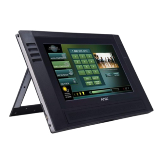
The AMX MVP-9000i-XX Modero Wireless Touch Panel is a mobile device that
communicates with a NetLinx Master via a standard 802.11a/b/g Wireless
Access Point. Panel to panel communication is enabled via a full duplex VoIP
intercom interface with SIP integration. The MVP-9000i utilizes a 9" Color Active
LCD to display a 800 x 480 pixel image using over 16.7M colors, offers control
via four programmable capacitive touch buttons and a capacitive touch
directional pad in addition to its touch screen, and features programmable
firmware that can be upgraded via the device's mini-USB port. The MVP-9000i
comes in black (MVP-9000i-GB, FG5967-01) and white (MVP-9000i-GW,
FG5967-02).
For detailed installation, configuration, programming, file transfer, and operating
instructions, refer to the MVP-9000i Operation/Reference Guide, available
on-line at www.amx.com.
Microphone
Stylus
C
MicroSD
memory
card slot
Mini-USB
connector
DC power
Docking Station interface connector
jack
FIG. 1
MVP-9000i-GB Touch Panel components
Specifications
MVP-9000i Specifications (FG5967-01/02)
Dimensions (HWD): • 7.62" x 10.98" x 1.06" (19.35 cm x 27.89 cm x 2.69 cm)
Weight:
• 3.40 lbs (1.54 kg)
Power Requirement
• Constant current draw: 1.7 A @ 12 VDC
(without charging):
• Startup current draw: 1.9 A @ 12 VDC
• If panel is mounted onto a TDS or WDS, add 0.1 A to the
above figures.
Power Requirement
Panel while charging battery:
(while charging):
• Constant current draw: 3.3 A @ 12 VDC
• Startup current draw: 3.9 A @ 12 VDC
• If panel is mounted onto a TDS or WDS, add 0.1 A to the
above figures.
Minimum power
• PS3.0 Power Supply (FG423-30)
supply required:
• PS-POE-AT High Power PoE Injector (FG423-81) through
the Table Docking Station and Wall Docking Station
Power Modes:
• ON: All necessary modules are powered up and device
remains online with the Netlinx Master.
• ASLEEP: Only the backlight will be turned off after the user
selectable time of inactivity has elapsed. Panel resumes
the ON mode in ~ 1 second.
• STANDBY: Power to all components other than the touch
screen is turned off after the user selectable time of
inactivity has elapsed. Device will turn back on by touching
the screen.
• SHUTDOWN: Power to all peripherals and components is
turned off. The system remains in this mode until it is
rebooted.
Certifications:
• FCC Class B
• CE
• IEC60950
• RoHS
• UL
• Telec - Japan approval (pending)
MVP-9000i
Directional pad
Capacitive touch buttons (4)
Speaker
Modero Wireless Touch Panel with Intercom
MVP-9000i Specifications (Cont.)
Battery Duration:
• Four days of normal use (25% On state, 25% Standby, and
• Five hours of continuous use (continuous On state).
Memory:
• 2GB internal microSD (1.5GB accessible to user)
Screen Properties:
• Screen resolution: 800 x 480 pixels (HV) @ 60 Hz refresh
• Aspect ratio: 16 x 9
• Brightness (luminance): 400 cd/m2
• Channel transparency: 8-bit Alpha blending
• Contrast ratio: 900:1 max.
• Display colors: 16.7M colors (8-bit color depth)
• Dot/pixel pitch: 0.246 mm
• Panel type: TFT Color Active-Matrix
Active Screen Area: • 7.75" x 7.40" (196.80 mm x 188.08 mm)
• 9" diagonal)
Viewing Angle:
• Up/Down/Left/Right: 85/85/85/85
Audio:
• Mono speaker: 4 Ohm, 2 Watts 300Hz cutoff frequency
Infrared
• IR Transmit only, including AMX 38KHz, AMX 455KHz, and
Communication:
Operating/Storage
• Operating Temperature: 0° C (32° F) to 40° C (104° F)
Environments:
• Operating Humidity: 20% - 85% RH
C
• Storage Temperature: -20° C (-4° F) to 60° C (140° F)
• Storage Humidity: 5% - 85% RH
Included
• PS4.4 Power Supply (FG423-45)
Accessories
• Stylus (pre-installed onto the left side of the unit)
Other AMX
• MVP-TDS-9-GB Black Table Docking Station (FG5967-10)
Equipment:
• MVP-TDS-9-GW White Table Docking Station (FG5967-11)
• MVP-WDS-9-GB Black Wall Docking Station (FG5967-12)
• MVP-WDS-9-GW White Wall Docking Station (FG5967-13)
• CC-MINIUSB Mini USB to PC Cable Adapter (FG5967-20)
• MVP-BP-9 Replacement Battery Pack (FG5967-21)
• PS-POE-AT High Power PoE Injector (FG423-81)
Connector Locations
Kickstand
FIG. 2
MVP-9000i-GW Kickstand View, showing connector locations
With the unit facing you, the microSD card slot (for loading and saving files such
as photos), the mini-AB USB port (for programming and downloading firmware)
and the DC power jack are located on the lower left side of the device. The
connector for the Table Docking Station is located on the bottom of the device.
The MVP-9000i may be operated while docked in a Table Docking Station or
Wall Docking Station, connected via the included power supply, or through
battery power.
The MVP-9000i supports an Ethernet over USB driver for panel downloads and
firmware updates through its mini-USB port instead of through a standard
Ethernet port. The mini-USB port may also be used, with an adaptor, with USB
memory sticks and USB headphones.
Note: The mini-USB port cannot be used to power the device or charge the
battery. Operation and charging must be done through the Docking Station
connector or through the power jack.
Warning: Although firmware upgrades can be done over wireless Ethernet; it is
strongly recommended that firmware KIT files be transferred over a direct USB
connection and only when the panel is connected to a power supply. If battery
Installation Guide
50% Shutdown).
rate
3rd party IR.
Stylus
MiicroSD
memory
card slot
Mini-USB port
DC power jack
Advertisement

Related Manuals for AMX MVP-9000i


Summary of Contents for AMX MVP-9000i
-
Page 1: Installation Guide
Panel resumes the ON mode in ~ 1 second. The MVP-9000i may be operated while docked in a Table Docking Station or • STANDBY: Power to all components other than the touch Wall Docking Station, connected via the included power supply, or through screen is turned off after the user selectable time of battery power. -
Page 2: Setup Pages
©2010 AMX. All rights reserved. AMX and the AMX logo are registered trademarks of AMX. AMX reserves the right to alter specifications without notice at any time. 3000 RESEARCH DRIVE, RICHARDSON, TX 75082 • 800.222.0193 • fax 469.624.7153 • technical support 800.932.6993 • www.amx.com...
Need help?
Do you have a question about the MVP-9000i and is the answer not in the manual?
Questions and answers