
Related Manuals for AMX MVP-8400ii


Summary of Contents for AMX MVP-8400ii
- Page 1 Operation/Reference Guide MVP-8400i ® ® 8.4" Modero ViewPoint Touch Panel with Intercom Touch Panels L a s t R e v i s e d : 1 /4 / 2 0 1 3...
- Page 2 AMX is not responsible for products returned without a valid RMA number. AMX is not liable for any damages caused by its products or for the failure of its products to perform. This includes any lost profits, lost savings, incidental damages, or consequential damages.
- Page 3 LICENSE GRANT. AMX grants to Licensee the non-exclusive right to use the AMX Software in the manner described in this License. The AMX Software is licensed, not sold. This license does not grant Licensee the right to create derivative works of the AMX Software.
- Page 4 FCC Information This device complies with Part 15 of the FCC Rules. Operation is subject to the following two conditions: (1) this device may not cause harmful interference, and (2) this device must accept any interference received; including interference that may cause undesired operation. Federal Communications Commission (FCC) Statement This equipment has been tested and found to comply with the limits for a Class B digital device, pursuant to Part 15 of...
-
Page 5: Table Of Contents
Table of Contents Table of Contents MVP-8400i Modero Viewpoint Wireless Touch Panel With Intercom ....1 Overview ........................1 Specifications ......................2 MVP-BP Power Pack ...................5 Overview ........................5 MVP-BP Specifications ....................5 Installing MVP-BP Batteries ..................5 NXA-CFSP Compact Flash ..................7 Overview ........................ - Page 6 Table of Contents USB..........................24 Prepare your PC for USB communication with the panel ..........24 Configure the panel for USB communication ..............24 Configure a Virtual NetLinx Master using NetLinx Studio ..........26 Ethernet ........................27 Master Connection to a Virtual Master via Ethernet ............. 27 Using G4 Web Control to Interact with a G4 Panel ..........
- Page 7 Table of Contents Calibrate Page......................72 G4 Web Control Settings Page ................73 Other Settings......................74 Cache Settings Page ..................... 74 Setting the image cache....................76 Clearing the image cache ....................76 Checking image cache status ..................76 Password Settings Page ....................77 SIP Settings Page ......................
- Page 8 Table of Contents Page Commands ..................... 95 @APG ............................. 95 @CPG ............................. 95 @DPG ............................. 96 @PDR ............................. 96 @PHE............................96 @PHP............................96 @PHT............................96 @PPA............................97 @PPF ............................97 @PPG ............................. 97 @PPK............................97 @PPM ............................. 98 @PPN ............................. 98 @PPT ............................
- Page 9 Table of Contents ^BRD ............................ 115 ^BSF............................. 116 ^BSM............................ 116 ^BSO ............................ 116 ^BSP............................. 116 ^BVL............................. 116 ^BVN............................ 117 ^BVP ............................ 117 ^BVT............................. 117 ^BWW ..........................117 ^CPF............................. 117 ^DLD ............................ 117 ^DPF ............................ 118 ^DTO............................ 118 ^ENA............................ 118 ^FON ........................... 118 ^GDI.............................
- Page 10 Table of Contents ?BCF............................. 128 ?BCT............................. 129 ?BMP............................ 129 ?BOP ............................ 130 ?BRD ............................ 130 ?BRT ............................. 130 ?BWW ..........................131 ?CHR ............................ 131 ?DTO ............................ 131 ?FBC............................. 131 ?FON............................ 132 ?ICO ............................. 132 ?JSB ............................. 133 ?JSI............................133 ?JST............................134 ?LOG ............................
- Page 11 Table of Contents ^KPS............................. 141 TPAGEON ..........................141 TPAGEOFF ........................... 141 @VKB............................ 141 WAKE ........................... 141 ^MBT............................ 142 ^MDC ........................... 142 ^MPS............................ 142 ^VKS ............................ 142 Embedded codes ....................143 Panel Setup Commands..................144 CLOCK..........................144 ^CFE............................. 144 ^CPR ............................ 144 ^CFS.............................
- Page 12 Table of Contents $BX ............................149 $BY............................149 $BN ............................149 Intercom Commands ..................... 150 ^ICE ............................. 150 ^ICM ............................ 150 ^ICS ............................. 150 ^MODEL?..........................150 SIP Commands ...................... 151 ^PHN-AUTOANSWER ......................151 ^PHN-CALL .......................... 151 ^PHN-DECLINE ........................151 ^PHN-INCOMING ........................ 151 ^PHN-LINESTATE.........................
- Page 13 How to Upload a Certificate File ................169 Erasing All Certificates From the Touch Panel............. 170 Appendix C: Troubleshooting ................171 Checking AMX USBLAN Device Connections via Windows Device Manager ....171 Checking AMX USBLAN Device Connections via NetLinx Studio ........ 172 USB Driver........................173 Panel Not in Listed as a Connected Device ..............
- Page 14 Table of Contents MVP-8400i 8.4" Modero® ViewPoint® Touch Panel with Intercom...
-
Page 15: Mvp-8400I Modero Viewpoint Wireless Touch Panel With Intercom
MVP panels feature programmable firmware that can be upgraded via either the wireless interface card or the mini-USB port. MVP panels utilize unique firmware kit files that can be downloaded from www.amx.com. MVP panels support AMX Computer Control, which enables remote viewing and control of any networked computer directly from the panel. -
Page 16: Specifications
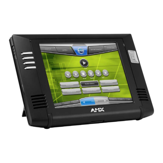
MVP-8400i Modero Viewpoint Wireless Touch Panel With Intercom Specifications The MVP-8400i panel utilizes an 8.4" Color Active LCD to display an 800 x 600 pixel resolution using 256K colors. Stylus Microphone Directional pad w/center select button Pushbuttons (4) Mini-USB connector Docking station interface connector Speaker Power connector... - Page 17 MVP-8400i Modero Viewpoint Wireless Touch Panel With Intercom MVP-8400i Specifications (FG5965-04) (Cont.) Weight: 1.85 lbs (0.84 kg) • with 1 battery: 2.25 lbs (1.02 kg) • with 2 batteries: 2.65 lbs (1.20 kg) MVP-8400i LCD • Aspect ratio: 4 x 3 Specifications: •...
- Page 18 • 80211xCF Wireless Interface Compact Flash card (Type 1) - pre-installed • PS4.4 Power Supply (FG423-44) • Stylus Other AMX Equipment: • CB-MVPWDS Rough-In Box (FG037-10) • CC-USB (Type A) to Mini-B 5-Wire programming cable (FG10-5965) • MVP-BP Power Pack (additional/spare) (FG5965-20) •...
-
Page 19: Mvp-Bp Power Pack
MVP-BP Power Pack MVP-BP Power Pack Overview The MVP-BP Power Pack (FG5965-20) is a rechargeable Lithium-Ion battery used to provide power to the MVP touch panels. Two MVP-BPs are included with each MVP-8400i touch panel. FIG. 3 MVP-BP Power Pack MVP-BPs can be charged with either a Table Top Docking Station (MVP-TDS), Wall/Flush Mount Docking Station (MVP-WDS), or the MVP panel itself. - Page 20 MVP-BP Power Pack Battery Compartment Cover Alignment Guide hole openings Battery connector Traction Grooves Battery pins Battery Battery slot 2 Removal Battery slot 1 Straps FIG. 4 Installing MVP-BP batteries into the MVP battery slots If you are only using one battery, use Battery Slot #1. To replace the battery compartment cover, use the alignment guide holes to align the cover with the edges of the battery compartment, and slide it back into place until it snaps shut.
-
Page 21: Nxa-Cfsp Compact Flash
NXA-CFSP Compact Flash NXA-CFSP Compact Flash Overview Every MVP panel is shipped with a 128 MB Compact Flash card. Compact Flash Card - Security All security user names and passwords (for the docking station) are stored in the Compact Flash card. After installing the Compact Flash card upgrade, all security user names and passwords need to be re-entered to enable security. -
Page 22: Removing The Installed Card
NXA-CFSP Compact Flash Grasp the bottom rim of the rear housing just above the MVP interface connector, and carefully pull the bottom rim away from the IR Emitter and up, to expose the internal components. Remove the trim from the top rim of the circuit board (FIG. 5). Removing the Installed Card Discharge any static electricity from your body by touching a grounded metal object and then locate the card slot on the main circuit board (FIG. - Page 23 NXA-CFSP Compact Flash Card removal grooves On-board Compact Flash connector (with pins) Insert with arrow facing towards the pins Connector opening FIG. 7 Removing/installing a Compact Flash Memory card Insert the new card firmly into the slot opening connector (FIG. 7) until the contact pins are completely inside the card and securely attached to the pin sockets.
- Page 24 NXA-CFSP Compact Flash MVP-8400i 8.4" Modero® ViewPoint® Touch Panel with Intercom...
-
Page 25: Panel Calibration
Modero panels are factory setup with specific demo touch panel pages. The first splash screen that appears indicates the panel is receiving power, beginning to load firmware, and preparing to display the default touch panel pages. When the panel is ready, the AMX Splash Screen is replaced by the Initial Panel Page. Calibrating the MVP Panels Press and hold the two lower external pushbuttons on both sides of the MVP (FIG. -
Page 26: Testing Your Calibration
Panel Calibration If the calibration was improperly set and you cannot return to the Calibration page (through the panel’s firmware); you can then access this firmware page via G4 WebControl where you can navigate to the Protected Setup page and press the Calibrate button through your VNC window. -
Page 27: Configuring Communications
Modero Setup and System Settings AMX Modero panels feature on-board Setup pages. Use the options in the Setup pages to access panel information and make various configuration changes. Accessing the Setup and Protected Setup Pages Press down and hold both the bottom, left pushbutton and down on the directional pad simultaneously for 3-5 seconds. -
Page 28: Configuring A Wireless Network Access
Appendix B - Wireless Technology section on page 163. For more information on utilizing the AMX Certificate Upload Utility in conjunction with the EAP security, refer to the section of the document entitled: Appendix B - Wireless Technology section on page 163. -
Page 29: Wireless Communication Using A Static Ip Address
Configuring Communications Modero connection IP info. Wireless Access Point Site Survey Button FIG. 13 Wireless Settings page (IP Settings section) Press Done after you are finished assigning the alpha-numeric string of the host name. The remaining greyed-out fields in the IP Settings section cannot be altered manually. Once the panel is rebooted, these values are obtained by the unit and displayed in the DNS fields after power-up. -
Page 30: Simple Versus Enterprise Configuration
Configuring Communications Simple versus Enterprise Configuration The Information/Configuration section of the Wireless Settings page includes two options for security, depending upon the intended network. The Simple setting is intended for small networks, such as with residential or small office applications. The Enterprise setting is intended for larger networks, with higher demands for security. To select configuration for a Simple network: From the Protected Settings page, select the Wireless Settings button on the upper-left to open the Wireless Settings page (FIG. - Page 31 Configuring Communications When selecting WEP as a Security Type, the button to the right of the Security Type may be toggled between 64 and 128. While the Password and Current Key fields are greyed out, the WEP keys are enabled: press each one to open the appropriate WEP Key keyboard and enter a WEP key, if necessary, and press Done to close the keyboard.
-
Page 32: Using The Site Survey Tool
Configuring Communications Using the Site Survey tool This tool allows a user to "sniff-out" all transmitting Wireless Access Points within the detection range of the internal NXA-WC80211GCF. Once pressed, the panel displays the Site Survey page, which contains categories such as:. ... -
Page 33: Step 2: Configure The Card's Wireless Security Settings
Configuring Communications Select a desired Access Point by touching the corresponding row. The up arrow and down arrow will be grayed out if there are ten or less access points detected. If there are more, then they will be enabled as appropriate so that the user can scroll through the list. -
Page 34: Configuring The Modero's Wireless Card For Secured Access To A Wap200G
The card should be given the SSID used by the target WAP. If this field is left blank, the unit will attempt to connect to the first available WAP. By default, all WAP200Gs use AMX as their assigned SSID value. -
Page 35: Automatically Set Ssid
Configuring Communications Automatically set SSID In the Protected Setup page: Select Wireless Settings. Press the Site Survey button. Select a WEP secured WAP from within the Wireless Site Survey page, and press the Connect button. Select a target WAP with the desired level of security Connecting to the... - Page 36 You must maintain the same case when entering this information. ABC is not the same as Abc. The alpha-numeric string is by default AMX but can later be changed to any 32-character entry. This string must be duplicated within the Network Name (SSID) field on the WAP. ...
-
Page 37: Configuring Multiple Wireless Moderos To Communicate To A Target Wap200G
Configuring Communications FIG. 23 WEP Key # Keyboard If you are entering a Current Key generated either by your target WAP or another Modero panel, within the WEP Keys section, touch the Key # button to launch the WEP Key # keyboard (FIG. 23), enter the characters and press Done when finished. -
Page 38: Step 3: Choose A Master Connection Mode
NetLinx Studio can be setup to run a Virtual Master where the PC acts as the Master by supplying its own IP Address for communication to the panel. For a PC to establish a USB connection with a Modero panel, it must have the AMX USBLAN driver installed. - Page 39 The first time the panel is recognized by the PC as a new USB device, a USB driver installation popup window (FIG. 26) is displayed. This window notifies you that the panel has been detected as a USB device, and the appropriate USB driver is being installed to establish communication with the panel. It also indicates that the AMX ®...
-
Page 40: Configure A Virtual Netlinx Master Using Netlinx Studio
Configuring Communications Configure a Virtual NetLinx Master using NetLinx Studio A Virtual NetLinx Master (VNM) is used when the target panel is not connected to a physical NetLinx Master. In this situation, the PC takes on the functions of a Master via a Virtual NetLinx Master. This connection is made by either using the PC’s Ethernet Address (via TCP/IP using a known PC’s IP Address as the Master) or using a direct mini-USB connection to communicate directly to the panel. -
Page 41: Ethernet
Verify the panel has been configured to communicate with the Wireless Access Point and verify the signal strength quality bargraph is On. Launch NetLinx Studio 2.x (default location is Start > Programs > AMX Control Disc > NetLinx Studio 2 > NetLinx Studio 2). - Page 42 Master (virtual or not). A Virtual Master system value can be set within the active AMX software applications such as: NetLinx Studio, TPD4, or IREdit. Press the Master IP/URL field to open a Keyboard and enter the IP Address of the PC used as the Virtual Master.
-
Page 43: Using G4 Web Control To Interact With A G4 Panel
Refer to the G4 Web Control Settings Page section on page 73 for more detailed field information. Verify your NetLinx Master (ME260/64 or NI-Series) has been installed with the latest firmware KIT file from www.amx.com. Refer to your NetLinx Master instruction manual for more detailed information on the use of the new web-based NetLinx Security. - Page 44 Configuring Communications From the Web Name keyboard, enter a unique alpha-numeric string to identify this panel. This information is used by the NetLinx Security Web Server to display on-screen links to the panel. The on-screen links use the IP Address of the panel and not the name for communication (FIG.
-
Page 45: Using Your Netlinx Master To Control The G4 Panel
Both HTTP and HTTPS Ports are enabled by default (via the Manage System > Server page). If the Master has been previously configured for secured communication, click OK to accept the AMX SSL certificate (if SSL is enabled) and then enter a valid username and password into the fields within the Login dialog. - Page 46 Configuring Communications FIG. 33 Web Control VNC installation and Password entry screens The G4 Web Control application is sent by the panel to the computer that is used for communication. Once the application is installed, this popup will no longer appear. This popup will only appear if you are connecting to the target panel using a different computer.
-
Page 47: Upgrading Mvp Firmware
Upgrading MVP Firmware Upgrading MVP Firmware Except for the MVP-KS (Kickstand for MVP Panels), all MVP panels and their accessories have on-board firmware which is upgradeable through the use of the latest NetLinx Studio. The MVP acts as a bridge between the NetLinx Studio program and the installed docking station. -
Page 48: Step 1: Configure The Panel For A Usb Connection Type
Navigate back to the System Settings page. Step 2: Prepare Studio for communication via the USB port Launch NetLinx Studio 2.x (default location is Start > Programs > AMX Control Disc > NetLinx Studio 2 > NetLinx Studio 2). Select Settings > Master Communication Settings, from the Main menu to open the Master Communication Settings dialog (FIG. -
Page 49: Step 3: Confirm And Upgrade The Firmware Via The Usb Port
Note that each kit file is intended for download to its corresponding panel. If the panel firmware version is not the latest available; locate the latest firmware file from www.amx.com. Click on the desired Kit file link and after you’ve accepted the Licensing Agreement, verify you have downloaded the Modero Kit file to a known location. -
Page 50: Upgrading The Docking Station Firmware Via Usb
Upgrading MVP Firmware Select Tools > Firmware Transfers > Send to NetLinx Device from the Main menu to open the Send to NetLinx Device dialog (B in FIG. 37). Verify the panel’s System and Device number values match those values listed within the System folder in the OnLine Tree tab of the Workspace window (A in FIG. -
Page 51: Step 2: Upgrade The Docking Station Firmware Via Usb
OnLine Tree tab of the Workspace window. The default Modero panel value is 10001. Locate the latest firmware file from the www.amx.com > Tech Center > Downloadable Files > Firmware Files > Modero Panels firmware (MVP Docking Stations: MVP-TDS/WDS) section of the website. - Page 52 Upgrading MVP Firmware Select Tools > Firmware Transfers > Send to NetLinx Device from the Main menu to open the Send to NetLinx Device dialog (FIG. 40). Verify the panel’s System and Device number values match those values listed within the System folder in the OnLine Tree tab of the Workspace window.
- Page 53 Upgrading MVP Firmware Although firmware upgrades can be done over wireless Ethernet; it is recommended that firmware KIT files be transferred over a direct USB connection and only when the panel is connected to a power supply. If battery power or wireless connection fails during a firmware upgrade, the panel flash file system may become corrupted.
- Page 54 Upgrading MVP Firmware MVP-8400i 8.4" Modero® ViewPoint® Touch Panel with Intercom...
-
Page 55: Setup Pages
Setup Pages Setup Pages AMX Modero panels feature on-board Setup pages. Use the options in the Setup pages to access panel information and make various configuration changes. To access the Setup pages, press the two lower external pushbuttons on either side of the panel simultaneously and hold for 3 seconds (FIG. -
Page 56: Setup Pages
Setup Pages Setup Pages The Setup page (FIG. 43) allows quick access to several basic panel properties: FIG. 43 MVP-8400 Setup page Features on this page include: Setup Page Navigation Buttons: The buttons along on the left side of the page provide access to secondary Setup pages (see following sections). -
Page 57: Information
Setup Pages Setup Page (Cont.) Display Timeout: Indicates the length of time that the panel can remain idle before activating Sleep mode (causing the LCD to power down). • Press the UP/DN buttons to increase/decrease the Display Timeout setting. Range = 0 - 240 (minutes). •... -
Page 58: Project Information Page
Receivers tab). • For example if you set the AMX IR 38K Port to 7 and then put a button on the panel with a channel code of 5 and a port of 7, it will trigger the IR code in slot 5 of the AMX IR 38K Port. -
Page 59: Panel Information Page
Project Information Page (Cont.) AMX IR 455K Port: Displays the AMX 455 kHz IR channel port used by the IR Emitter on the panel. IR User Def 1 Port: Displays the User Defined IR channel port used by the IR Emitter on the panel. - Page 60 Setup Pages Features on this page include: Panel Information Page Back: Saves all changes and returns to the previous page. The icon to the left of the Connection Status Icon displays whether the current WiFi/Wired icon: connection to the Master is Wireless (image of a radio antenna) or Wired (image of three networked computers).
-
Page 61: Time & Date Settings
Setup Pages Time & Date Settings The options on the Time & Date Settings page (FIG. 47) allow you to set and adjust time and date information on the NetLinx Master. If the time and/or date on the Master is modified, all connected devices will be updated to reflect the new information. -
Page 62: Audio Settings
Setup Pages Time & Date Settings Page (Cont.) Set Date/Time: Use the UP/DN arrow buttons to adjust the Master’s calendar date and time. The blue icon indicates which field is currently selected (see FIG. 47). • Year range = 2000 - 2037 •... -
Page 63: Wav Files - Supported Sample Rates
Setup Pages Audio Settings Page (Cont.) Master Volume: This section allows you to alter the current master volume level: • Use the UP/DN buttons to adjust the volume level (range = 0 - 100). • The Master Volume bargraph indicates the current volume level. •... -
Page 64: Battery Settings
Setup Pages Battery Settings The options on this page allow you to set power warning preferences, monitor battery status information, and adjust the display times for battery warnings. This page is populated with information from MVP-BP batteries in the panel, as well as batteries in a connected MVP-TDS/WDS docking station (FIG. - Page 65 Setup Pages Battery Settings Page (Cont.) Panel Shutdown: This value determines the number of minutes that would need to pass before the panel automatically shuts-down. Once shutdown, the unit would have to be restarted. The UP/DN buttons alter the timeout value (in minutes). A value of 0 disables this feature.
-
Page 66: Protected Setup Pages
Setup Pages Protected Setup Pages The Protected Setup page (FIG. 50) provides secured access to advanced panel configuration options, including communication and security settings. Enter the factory default password (1988) into the password keypad to access this page. FIG. 50 Protected Setup page showing default values Features on the Protected Setup page include: Protected Setup Page... - Page 67 System Recovery: • Remove User Pages - allows you remove all TPD4 touch panel pages currently on the panel, including the pre-installed AMX Demo pages. This option invokes a Confirmation dialog, prompting you to confirm your selection before removing the panel pages.
-
Page 68: Protected Setup Navigation Buttons
Setup Pages Channel Code Channel Port 3,132 BUTTON 3,50 Level Port Address Port Channel Code Address Code FIG. 51 Function Show example Protected Setup Navigation Buttons The Protected Setup Navigation Buttons (FIG. 52) appear on the left of the panel screen when the Protected Setup page is currently active. -
Page 69: System Settings Page
Setup Pages System Settings Page The System Settings page (FIG. 53) displays sets the NetLinx Master’s communication settings. FIG. 53 System Settings page The elements of this page include: System Settings Page Elements Back: Saves all changes and returns to the previous page. The icon to the left of the Connection Status Icon displays whether the current ... - Page 70 Setup Pages System Settings Page Elements Master Connection (Cont.): Mode Cycles between the connection modes: URL, Listen, and Auto. (Ethernet Only - disabled when USB is selected) • URL - In this mode, enter the IP/URL, Master Port Number, and username/password (if used) on the Master.
-
Page 71: Wireless Settings Page
Setup Pages Wireless Settings Page Use the options on the Wireless Settings page (FIG. 54) to configure communication settings for the wireless CF card (802.11g), and read the device number assigned to the panel. FIG. 54 Wireless Settings page (reads from and assigns values to the WAP) Features on this page include: Wireless Settings Page Back:... - Page 72 Setup Pages Wireless Settings Page (Cont.) IP Settings (Cont.): MAC Address This unique address identifies the wireless Ethernet card in the panel (read-only). Active Roaming on When enabled, the device is actively roaming on the channels 1, 6, and 11. By Channels 1,6,11 default, Active Roaming is disabled.
- Page 73 Setup Pages FIG. 55 Wireless Security: Simple Mode Wireless Security: Simple Mode Security Type: This field may be switched between WEP, WPA-PSK, and Open. If WEP is selected, the button to the right may be switched between 64 and 128. •...
- Page 74 (panel) before allowing it access to the network. (Refer to the EAP- TTLS Settings section on page 68 for details. For information on uploading a certificate file, refer to the AMX Certificate Upload Utility section on page 167.) • EAP-TLS security is designed for wireless environments where it is necessary to securely transmit data over a wireless network by adding an additional level of security protocol via the use of a private key.
-
Page 75: Wireless Settings
Setup Pages Wireless Security: Enterprise Mode (Cont.) Press this field to enter a password for wireless access in the Password Password: keypad. (NOTE: this field is greyed out when selecting EAP-TLS as a Security Type.) Certificate Authority: Press this field to enter the file location for a Certificate Authority certificate in the Certificate Authority (CA) keypad. -
Page 76: Open Settings
• The SSID is case sensitive and must not exceed 32 characters. • Make sure this setting is the same for all points in your wireless network. • NXA-WAP200Gs use AMX as their default SSID. • If this field is left blank, the panel will attempt to connect to the first available WAP. - Page 77 • The Passphrase generator is case sensitive. Note: This Key generator is unique to Modero panels and does not generate the same keys as non-AMX wireless devices. For example, a Current Key string generated anywhere else will not match those created on Modero panels.
-
Page 78: Wpa-Psk Settings
• The SSID is case sensitive and must not exceed 32 characters. • Make sure this setting is the same for all points in your wireless network. • NXA-WAP200Gs use AMX as their default SSID. • If this field is left blank, the panel will attempt to connect to the first available WAP. -
Page 79: Eap-Leap Settings
This works in tandem with the Password string which is similar to the password entered to gain access to a secured workstation. Typically, this is in the form of a username such as: jdoe@amx.com. Password: Opens an on-screen keyboard. Enter the network password string specified... -
Page 80: Eap-Fast Settings
This works in tandem with the Password string which is similar to the password entered to gain access to a secured workstation. Typically, this is in the form of a username such as: jdoe@amx.com. Anonymous Identity: Opens an on-screen keyboard. Enter an IT provided alpha-numeric string which (similar to the username) used as the identity, but that does not represent a real user. -
Page 81: Eap-Peap Settings
This works in tandem with the Password string which is similar to the password entered to gain access to a secured workstation. Typically, this is in the form of a username such as: jdoe@amx.com. Password: Opens an on-screen keyboard. Enter the network password string specified... -
Page 82: Eap-Ttls Settings
• The SSID is case sensitive and must not exceed 32 characters. • Make sure this setting is the same for all points in your wireless network. • NXA-WAP200Gs use AMX as their default SSID. • With EAP security, the SSID of the WAP must be entered. If it is left blank, the panel will try to connect to the first access point detected that supports EAP. - Page 83 This works in tandem with the Password string which is similar to the password entered to gain access to a secured workstation. Typically, this is in the form of a username such as: jdoe@amx.com. Anonymous Identity: Opens an on-screen keyboard. Enter an IT provided alpha-numeric string which (similar to the username) used as the identity, but that does not represent a real user.
-
Page 84: Eap-Tls Settings
This works in tandem with the Password string which is similar to the password entered to gain access to a secured workstation. Typically, this is in the form of a username such as: jdoe@amx.com. Certificate Authority: When pressed, the panel displays an on-screen Certificate Authority (CA) File Location keyboard which allows you to enter the name of the certificate authority file which is used to validate the server certificate. -
Page 85: Client Certificate Configuration
Format is: PKCS12 First file contains the client certificate, second file not supported not supported contains the private key. Format is: PKCS12 AMX supports the following security certificates PEM (Privacy Enhanced Mail) DER (Distinguished Encoding Rules) ... -
Page 86: Calibrate Page
Setup Pages Calibrate Page This page (FIG. 57) allows you to calibrate the touch panel for accurate button selection. FIG. 57 Calibration page Press and hold the two lower button on both sides of the display for 6 seconds to access the Calibration page (see FIG. -
Page 87: G4 Web Control Settings Page
Setup Pages G4 Web Control Settings Page An on-board VNC (Virtual Network Computing) server allows the panel to connect to any remote PC running a VNC client. Once connected, the client can view and control the panel remotely. The options on this page allow you to enable/ disable G4 Web Control functionality(FIG. -
Page 88: Other Settings
Setup Pages G4 Web Control Page (Cont.) Maximum Number of Displays the maximum number of users that can be simultaneously connected Connections to this panel via VNC. Default = 1. Current Connection Count Displays the number of users currently connected to this panel via VNC. G4 Web Control Timeout: Sets the length of time (in minutes) that the panel can remain idle (no cursor movements) before the G4 Web Control session is terminated. - Page 89 DynaMo is an extension of the Dynamic images feature of AMX G4 devices that provides playback of M-JPEG images. DynaMo Images are Motion-JPEG (or "M-JPEG") images that exist on an HTTP server, external to the panel.
-
Page 90: Setting The Image Cache
Setup Pages Cache Settings Page Elements (Cont.) Flash/RAM Cache Expires Press the Up and Down arrows to change the amount of time the images stay in cache memory. The options are: • Never • 2 Hours • 8 Hours • 1 Day •... -
Page 91: Password Settings Page
Setup Pages Press the Cache button in the Protected Setup Navigation Buttons section. This opens the Image Cache page. All status information is located in the Image Cache Status section of the page. Password Settings Page The options on the Password Settings page enable you to assign the passwords required for users to access the Protected Setup page, and to release the MVP from a MVP-TDS or MVP-WDS docking station (FIG. -
Page 92: Sip Settings Page
Setup Pages Password Settings Page (Cont.) User Access: Use these buttons to access and modify the user name/password combinations required for removing the panel from a docking station. The number of user access passwords on the panel is limited only by the amount of storage memory available. - Page 93 Setup Pages Features on this page include: SIP Settings Page Back: Saves all changes and returns to the previous page. The icon to the left of the Connection Status Icon displays whether the current WiFi/Wired icon: connection to the Master is Wireless (image of a radio antenna) or Wired (image of three networked computers).
-
Page 94: Tools
Setup Pages Tools The Tools button provides a menu to select either the Panel Connection Logs Page section on page 80, the Panel Statistics Page section on page 82, or the Connection Utility Page section on page 83. Select any of the options to access that page. -
Page 95: Checking The Panel Connection Logs
Setup Pages Features on this page include: Panel Connection Logs Page Back: Saves all changes and returns to the previous page. The icon to the left of the Connection Status Icon displays whether the current WiFi/Wired icon: connection to the Master is Wireless (image of a radio antenna) or Wired (image of three networked computers). -
Page 96: Panel Statistics Page
Setup Pages Panel Statistics Page The options on the Panel Statistics page allow you to track the connection status for the panel. The Panel Statistics page tracks ICSP messages, Blink messages, Ethernet connection statistics, and Wireless connection statistics (FIG. 61). FIG. -
Page 97: Checking The Panel Statistics
Setup Pages Panel Statistics Page (Cont.) Total • Received - The total Blink messages received by the panel. • Missed - The total Blink messages missed by the panel. Last 15 Minutes • Received - The total Blink messages received by the panel in the last 15 minutes. -
Page 98: Using The Connection Utility
Setup Pages Features on this page include: Connection Utility Page Connection Status icon: The icon in the upper-right corner of the utility provides a constant visual indication of current connection status. A message is sent to the master once per second and expects a response. •... -
Page 99: Eap Security & Server Certificates
EAP Security & Server Certificates EAP Security & Server Certificates Overview The following EAP types all support a server certificate: EAP-PEAP EAP-TTLS EAP-TLS All three of these certificate-using security methods are documented in the following sections. EAP Authentication goes a step beyond just encrypting data transfers, but also requires that a set of credentials be validated before the client (panel) is allowed to connect to the rest of the network (FIG. - Page 100 EAP Security & Server Certificates MVP-8400i 8.4" Modero® ViewPoint® Touch Panel with Intercom...
-
Page 101: Full Duplex Intercom
Incorporating an intercom capable panel into your NetLinx system Download the module for the intercom panel from www.amx.com, and include it in your NetLinx project file. For searching purposes, the module manufacturer is AMX and the model is Intercom. -
Page 102: Setting Intercom Auto Answer
Full Duplex Intercom Extend Call Popup FIG. 69 Press Exit when you are finished. Setting Intercom Auto Answer Select the Setup button on your intercom page. Press the button beneath Auto-Answer to toggle the option. The button indicates its current state. Press Exit when you are finished. -
Page 103: Allowing A Panel To Monitor
Full Duplex Intercom Press the button beneath Allow This Panel to be Monitored to toggle the option. The button indicates its current state. (FIG. 71) Room Monitored FIG. 71 Press Back to return to the intercom setup pages. Press Exit when you are finished. Allowing a panel to monitor Select the Setup button on your intercom page. -
Page 104: Sample Intercom Page
Full Duplex Intercom Sample Intercom Page The module for duplex intercom capable panels includes user pages. While you can create your own intercom directory page (see Creating Intercom Pages section on page 93), it is possible to use the panel with the page below. Sample Intercom Page FIG. - Page 105 Full Duplex Intercom Sample Intercom Page (Cont.) No. Name Description Channel Address Level Port:Code Port:Code Port:Code Panel Directory Room Name The name of a panel in the intercom directory. You can call the panel, enact privacy against the panel and monitor the panel.
-
Page 106: Answering An Incoming Call
Full Duplex Intercom Sample Intercom Page (Cont.) No. Name Description Channel Address Level Port:Code Port:Code Port:Code Monitor Panel Display only; indicates the 1:35 panel is being monitored by another panel. Intercom Microphone Level A Bargraph in TPDesign4 that 0:10 sets the volume of the intercom microphone. -
Page 107: Creating Intercom Pages
Creating Intercom Pages The easiest method of creating your own intercom pages is to start with the pages provided by AMX in the module download .ZIP file. You can change the aesthetics of the pages as long as the channel, address, level and links remain untouched. - Page 108 Full Duplex Intercom MVP-8400i 8.4" Modero® ViewPoint® Touch Panel with Intercom...
-
Page 109: Programming
Programming Programming Overview You can program the touch panel, using the commands in this section, to perform a wide variety of operations using Send_Commands and variable text commands. A device must first be defined in the NetLinx programming language with values for the Device: Port: System (in all programming examples - Panel is used in place of these values and represents all Modero panels). -
Page 110: Dpg
Programming Page Commands (Cont.) @DPG Syntax: "'@DPG-<popup page name>;<popup group name>'" Delete a specific popup page from Variable: specified popup popup page name = 1 - 50 ASCII characters. Name of the popup page. group if it exists. popup group name = 1 - 50 ASCII characters. Name of the popup group. Example: SEND_COMMAND Panel,"'@DPG-Popup1;Group1'"... -
Page 111: Ppa
Programming Page Commands (Cont.) @PPA If the page name is empty, the current page is used. Same as the ’Clear Page’ command in TPDesign4. Close all popups Syntax: on a specified page. "'@PPA-<page name>'" Variable: page name = 1 - 50 ASCII characters. Name of the page the popup is displayed On. Example: SEND_COMMAND Panel,"'@PPA-Page1'"... -
Page 112: Ppm
Programming Page Commands (Cont.) @PPM A Modal popup page, when active, only allows you to use the buttons and features on that popup page. All other buttons on the panel page are inactivated. Set the modality Syntax: of a specific popup page to "'@PPM-<popup page name>;<mode>'"... -
Page 113: Psp
Programming Page Commands (Cont.) @PSP Only 1 coordinate is ever needed for an effect; however, the command will specify both. This command sets the location at which the effect will begin at. Set the show Syntax: effect position. "'@PSP-<popup page name>;<x coordinate>,<y coordinate>'" Variable: popup page name = 1 - 50 ASCII characters. -
Page 114: Ppog
Programming Page Commands (Cont.) If the page name is empty, the current page is used (see example 2). Toggling refers to the PPOG activating/deactivating (On/Off) of a popup page. This command works in the same way Toggle a as the ’Toggle Popup’... -
Page 115: Programming Numbers
Programming Programming Numbers The following information provides the programming numbers for colors, fonts, and borders. Colors can be used to set the colors on buttons, sliders, and pages. The lowest color number represents the lightest color- specific display; the highest number represents the darkest display. For example, 0 represents light red, and 5 is dark red. RGB triplets and names for basic 88 colors RGB Values for all 88 Basic Colors Index No. - Page 116 Programming RGB Values for all 88 Basic Colors (Cont.) Index No. Name Green Blue Cyan Medium Cyan Dark Cyan Very Dark Cyan Very Light Aqua Light Aqua Aqua Medium Aqua Dark Aqua Very Dark Aqua Very Light Blue Light Blue Blue Medium Blue Dark Blue...
-
Page 117: Font Styles And Id Numbers
Arial Courier New Arial Courier New Arial Courier New Arial AMX Bold Arial AMX Bold Arial Bold AMX Bold Arial Bold 32 - Variable Fonts start at 32. You must import fonts into a TPDesign4 project file. The font ID numbers are ... -
Page 118: Border Styles And Programming Numbers
You cannot use the following number values for programming purposes when changing border styles. TPD4 border styles can ONLY be changed by using the name. TPD4 Border Styles by Name Border styles Border styles None Circle 155 AMX Elite -L Circle 165 AMX Elite -M Circle 175 AMX Elite -S Circle 185 Bevel -L... - Page 119 Programming TPD4 Border Styles by Name (Cont.) Border styles Border styles Diamond 145 Menu Top Rounded 15 Diamond 155 Menu Top Rounded 25 Diamond 165 Menu Top Rounded 35 Diamond 175 Menu Top Rounded 45 Diamond 185 Menu Top Rounded 55 Diamond 195 Menu Top Rounded 65 Double Bevel -L...
-
Page 120: Button Commands
Programming TPD4 Border Styles by Name (Cont.) Border styles Border styles Menu Left Rounded 95 Menu Left Rounded 155 Menu Left Rounded 105 Menu Left Rounded 165 Menu Left Rounded 115 Menu Left Rounded 175 Menu Left Rounded 125 Menu Left Rounded 185 Menu Left Rounded 135 Menu Left Rounded 195 Menu Left Rounded 145... -
Page 121: Bat
Programming "^" Button Commands (Cont.) ^BAT Syntax: Append "'^BAT-<vt addr range>,<button states range>,<new text>'" non-unicode text. Variable: variable text address range = 1 - 4000. button states range = 1 - 256 for multi-state buttons (0 = All states, for General buttons 1 = Off state and 2 = On state). -
Page 122: Bcf
Programming "^" Button Commands (Cont.) ^BCF Only if the specified fill color is not the same as the current color. Note: Color can be assigned by color name (without spaces), number or R,G,B value Set the fill color to (RRGGBB or RRGGBBAA). the specified color. -
Page 123: Bfb
Programming "^" Button Commands (Cont.) ^BFB ONLY works on General-type buttons. Syntax: Set the feedback type of the button. "'^BFB-<vt addr range>,<feedback type>'" Variable: variable text address range = 1 - 4000. feedback type = (None, Channel, Invert, On (Always on), Momentary, and Blink). Example: SEND_COMMAND Panel,"'^BFB-500,Momentary'"... -
Page 124: Bmc
Programming "^" Button Commands (Cont.) ^BMC Note that the source is a single button state. Each state must be copied as a separate command. The <codes> section represents what attributes will be copied. All codes are Button copy 2 char pairs that can be separated by comma, space, percent or just ran together. -
Page 125: Bmf
Programming "^" Button Commands (Cont.) ^BMF Syntax: "'^BMF-<vt addr range>,<button states range>,<data>'" Set any/all button parameters by Variables: sending variable text address char array = 1 - 4000. embedded codes button states range = 1 - 256 for multi-state buttons (0 = All states, for General buttons and data. - Page 126 Programming "^" Button Commands (Cont.) ^BMF For some of these commands and values, refer to theRGB Values for all 88 Basic (Cont.) Colors table on page 101. ’%CF<on fill color>’ = Set Fill Color. ’%CB<on border color>’ = Set Border Color. ’%CT<on text color>’...
-
Page 127: Bmi
Programming "^" Button Commands (Cont.) ^BMI Mask image is used to crop a borderless button to a non-square shape. This is typically used with a bitmap. Set the button Syntax: mask image. "'^BMI-<vt addr range>,<button states range>,<mask image>'" Variable: variable text address range = 1 - 4000. button states range = 1 - 256 for multi-state buttons (0 = All states, for General buttons... -
Page 128: Bnc
Programming "^" Button Commands (Cont.) ^BNC Syntax: Clear current "'^BNC-<vt addr range>,<command value>'" TakeNote Variable: annotations. variable text address range = 1 - 4000. command value = (0= clear, 1= clear all). Example: SEND_COMMAND Panel,"'^BNC-973,0'" Clears the annotation of the TakeNote button with variable text 973. ^BNN Syntax: Set the TakeNote ... -
Page 129: Bor
Sets the border by number (#10) to those buttons with the variable text range of 500-504 & 510-515. SEND_COMMAND Panel,"'^BOR-500.504&510,AMX Elite -M'" Sets the border by name (AMX Elite) to those buttons with the variable text range of 500-504 & 510-515. The border style is available through the TPDesign4 border-style drop-down list. Refer to theTPD4 Border Styles by Name table on page 104 for more information. -
Page 130: Bsf
Programming "^" Button Commands (Cont.) ^BSF Note: Select one button at a time (single variable text address). Do not assign a variable text address range to set focus to multiple buttons. Only one variable text address can be Set the focus to in focus at a time. -
Page 131: Bvn
Programming "^" Button Commands (Cont.) ^BVN Syntax: "'^BVN-<vt addr range>,<network name>'" Set the network name for the Variable: specified address. variable text address range = 1 - 4000. network name = 1 - 50 ASCII characters. Example: SEND_COMMAND Panel,"'^BVN-500,191.191.191.191'" Sets the network name to ’191.191.191.191’ for the specific control button. ^BVP Syntax: Set the network ... -
Page 132: Dpf
Programming "^" Button Commands (Cont.) ^DPF Syntax: "'^DFP-<vt addr range>,<actions>,<page name>'" Delete page flips from button if it Variable: already exists. variable text address range = 1 - 4000. actions = Stan[dardPage] - Flip to standard page Prev[iousPage] - Flip to previous page Show[Popup] - Show Popup page ... -
Page 133: Gdi
Programming "^" Button Commands (Cont.) ^GDI Syntax: Change the "'^GDI-<vt addr range>,<bargraph drag increment>'" bargraph drag Variable: increment. variable text address range = 1 - 4000. bargraph drag increment = The default drag increment is 256. Example: SEND_COMMAND Panel,"'^GDI-7,128'" Sets the bargraph with variable text 7 to a drag increment of 128. -
Page 134: Gru
Programming "^" Button Commands (Cont.) ^GRU Syntax: Change the "'^GRU-<vt addr range>,<bargraph ramp up time>'" bargraph Variable: ramp-up time in variable text address range = 1 - 4000. 1/10th of a bargraph ramp up time = In 1/10th of a second intervals. second. -
Page 135: Irm
Programming "^" Button Commands (Cont.) ^IRM Pulse the given IR channel for onTime in tenths of seconds. Delay offTime in tenths of a second before the next IR pulse is allowed. ^IRM allows the command itself to specify the Set the IR port number. -
Page 136: Jst
Programming "^" Button Commands (Cont.) ^JST The alignment of 0 is followed by ',<left>,<top>'. The left and top coordinates are relative to the upper left corner of the button. Set text Syntax: alignment using a numeric keypad "'^JST-<vt addr range>,<button states range>,<new text layout for those alignment>'"... -
Page 137: Skt
Programming "^" Button Commands (Cont.) ^SKT Syntax: "'^SKT'" Enable socket touch Example: SEND COMMAND Panel,"'^SKT'" Example: Press,34,203 Release,34,21 Move,30,20 Opens up a listening TCP socket on port specified by send_command (must be > 1023). User can connect to socket and read touch values for the panel. Format of the output is: <Press/Release/Move>,<x-coordinate>,<y-coordinate>... -
Page 138: Top
Programming "^" Button Commands (Cont.) ^TOP If enabled, Press/Move/Release events are sent to the Master as string events. Syntax: Enables/disables touch output to "'^TOP-<state>'" Master <state> is 0(disable) 1(presses/releases), 2(moves), 3(press/move/release). Note: Move should be used with caution. This setting can generate a significant amount of traffic to the master depending on user interaction. -
Page 139: Miscellaneous Mvp Strings Back To The Master
Programming Miscellaneous MVP Strings back to the Master The following two strings are sent by the MVP panel back to the communicating Master: MVP Strings to Master undock <master> This is sent to the target Master when the MVP is undocked. •... -
Page 140: Text Effects Names
Programming Text Effects Names The following is a listing of text effects names (associated with the ^TEF command on page 123). Text Effects • Glow -S • Medium Drop Shadow 1 • Hard Drop Shadow 1 • Glow -M • Medium Drop Shadow 2 •... -
Page 141: Button Query Commands
Programming Button Query Commands Button Query commands reply back with a custom event. There will be one custom event for each button/state combination. Each query is assigned a unique custom event type. The following example is for debug purposes only: NetLinx Example: CUSTOM_EVENT[device, Address, Custom event type] DEFINE_EVENT CUSTOM_EVENT[TP,529,1001]... -
Page 142: Bcb
Programming These fields are populated differently for each query command. The text length (String Encode) field is not used in any command. Button Query Commands ?BCB Syntax: "'?BCB-<vt addr range>,<button states range>'" Get the current border color. Variable: variable text address range = 1 - 4000. button states range = 1 - 256 for multi-state buttons (0 = All states, for General buttons... -
Page 143: Bct
Programming Button Query Commands (Cont.) ?BCT Syntax: "'?BCT-<vt addr range>,<button states range>'" Get the current text color. Variable: variable text address range = 1 - 4000. button states range = 1 - 256 for multi-state buttons (0 = All states, for General buttons 1 = Off state and 2 = On state). -
Page 144: Bop
Programming Button Query Commands (Cont.) ?BOP Syntax: "'?BOP-<vt addr range>,<button states range>'" Get the overall button opacity. Variable: variable text address range = 1 - 4000. button states range = 1 - 256 for multi-state buttons (0 = All states, for General buttons 1 = Off state and 2 = On state). -
Page 145: Bww
Programming Button Query Commands (Cont.) ?BWW Syntax: "'?BWW-<vt addr range>,<button states range>'" Get the current word wrap flag Variable: status. variable text address range = 1 - 4000. button states range = 1 - 256 for multi-state buttons (0 = All states, for General buttons 1 = Off state and 2 = On state). -
Page 146: Fon
Programming Button Query Commands (Cont.) ?FON Syntax: "'?FON-<vt addr range>,<button states range>'" Get the current font index. Variable: variable text address range = 1 - 4000. button states range = 1 - 256 for multi-state buttons (0 = All states, for General buttons 1 = Off state and 2 = On state). -
Page 147: Jsb
Programming Button Query Commands (Cont.) ?JSB Syntax: "'?JSB-<vt addr range>,<button states range>'" Get the current bitmap Variable: justification. variable text address range = 1 - 4000. button states range = 1 - 256 for multi-state buttons (0 = All states, for General buttons 1 = Off state and 2 = On state). -
Page 148: Jst
Programming Button Query Commands (Cont.) ?JST Syntax: "'?JST-<vt addr range>,<button states range>'" Get the current text justification. Variable: variable text address range = 1 - 4000. button states range = 1 - 256 for multi-state buttons (0 = All states, for General buttons 1 = Off state and 2 = On state). -
Page 149: Sta
Programming Button Query Commands (Cont.) ?STA Syntax: "'?STA'" Dump XML Panel Stats Returned in MULTIPLE Custom events (size of strings are limited per message). Values in Custom event will state the number of messages and how many total bytes of xml data. Value 1 = 1 (which one of multiple events is this (1 based)) Value 2 = 5 (total number of events required to send this string) Value 3 = total size in bytes of string... -
Page 150: Tef
Programming Button Query Commands (Cont.) ?TEF Syntax: "'?TEF-<vt addr range>,<button states range>'" Get the current text effect name. Variable: variable text address range = 1 - 4000. button states range = 1 - 256 for multi-state buttons (0 = All states, for General buttons 1 = Off state and 2 = On state). -
Page 151: Panel Runtime Operations
Programming Button Query Commands (Cont.) ?VOL Syntax: ?VOL-<volume value> Show the Master Volume Variable: information. Value1=master volume value ?WIF Syntax: Show the Text=<WAP MAC address>,<SSID>,Channel # Wireless Settings Variable: information Value1=Link Quality (percent) Value2=Signal Strength (percentage) Panel Runtime Operations Serial Commands are used in the AxcessX Terminal Emulator mode. -
Page 152: Akeyr
Programming Panel Runtime Operation Commands (Cont.) AKEYR Remove keyboard or keypad that was displayed using 'AKEYB', 'AKEYP', 'PKEYP', @AKB, @AKP, @PKP, @EKP, or @TKP commands. Remove the Syntax: Keyboard/ Keypad. "'AKEYR'" Example: SEND COMMAND Panel,"'AKEYR'" Removes the Keyboard/Keypad. @AKP Keypad string is set to null on power up and is stored until power is lost. The Prompt Text is optional. -
Page 153: Ekp
Programming Panel Runtime Operation Commands (Cont.) @EKP Pops up the keypad icon and initializes the text string to that specified. The Prompt Text is optional. Extend the Syntax: Keypad. "'@EKP-<initial text>;<prompt text>'" Variables: initial text = 1 - 50 ASCII characters. prompt text = 1 - 50 ASCII characters. -
Page 154: Sou
Programming Panel Runtime Operation Commands (Cont.) @SOU Syntax: "'@SOU-<sound name>'" Play a sound file. Variables: sound name = Name of the sound file. Supported sound file formats are: WAV & MP3. Example: SEND COMMAND Panel,"'@SOU-Music.wav'" Plays the 'Music.wav' file. @SSL Syntax: Change Sleep "'@SSL-<string>'"... -
Page 155: Input Commands
Programming Panel Runtime Operation Commands (Cont.) TPAGEON This command turns On page tracking, whereby when the page or popups change, a string is sent to the Master. This string may be captured with a CREATE_BUFFER Turn On page command for one panel and sent directly to another panel. tracking. -
Page 156: Mbt
Programming Input Commands (Cont.) ^MBT Syntax: "'^MBT-<0-3>'" Set the mouse button mode for Variable: the virtual PC. 0 = None. 1 = Left. 2 = Middle. 3 = Right. Example: SEND COMMAND Panel,"'^MBT-1'" Sets the mouse button mode for the virtual PC to LEFT. ^MDC Syntax: Set the mouse... -
Page 157: Embedded Codes
Programming Embedded codes The following is a list of G4 compatible embedded codes: Embedded Codes Decimal numbers Hexidecimal values Virtual keystroke ($08) Backspace ($0D) Enter ($1B) ($80) CTRL key down ($81) ALT key down ($82) Shift key down ($83) ($84) ($85) ($86) ($87) -
Page 158: Panel Setup Commands
Programming Panel Setup Commands These commands are case insensitive. Panel Setup Commands CLOCK Syntax: Sets the time and date “’CLOCK mm-dd-yy hh:mm:ss’” on the panel. Variables: mm = Month dd = Day yy = Year hh = Hour mm = Minute ss = Second Example: SEND_COMMAND Panel, “’CLOCK 04-19-76 19:16:00’”... -
Page 159: Cfsm
Programming Panel Setup Commands (Cont.) ^CFSM Syntax: “’^CFSM’” Sets the Flash cache to the maximum Variable: available size allowed There is no parameter for this command. for backup Flash cache. Example: (determined by taking SEND_COMMAND Panel, “’^CFSM’” 75% of free Flash Modifies the Flash cache size to the maximum available size for the device. -
Page 160: Icm-Speakerlevel
Programming Panel Setup Commands (Cont.) ^ICM-SPEAKERLEVEL Syntax: "'^ICM-SPEAKERLEVEL,<level>'" Set the speaker level during an intercom call. Variables: 0 - 100 volume levels Example: SEND_COMMAND Panel, “^ICM-SPEAKERLEVEL,55” Sets the speaker volume level to 55. ^ICM-MICLEVEL Syntax: Used to set the "'^ICM-MICLEVEL,<level>'"... -
Page 161: Dynamic Image Commands
Adds a new resource. •The resource name is ’New Image’ •%P (protocol) is an HTTP •%H (host name) is AMX.COM •%A (file path) is Lab/Test_file •%F (file name) is test.jpg. Note that the %%5F in the file path is actually encoded as %5F. -
Page 162: Raf, ^Rmf - Embedded Codes
Programming Dynamic Image Commands (Cont.) ^RMF Modifies any and all resource parameters by sending embedded codes and data. Modify an Since the embedded codes are preceded by a '%' character, any '%' character contained in the URL must be escaped with a second '%' character (see example). existing resource. -
Page 163: Escape Sequences
Current state Address code Address port Channel code Channel port Level code Level port X Resolution of Current button Y Resolution of Current button Name of Button For instance, http://www.amx.com/img.asp?device=$DV would become http://www.amx.com/img.asp?device=10001. MVP-8400i 8.4" Modero® ViewPoint® Touch Panel with Intercom... -
Page 164: Intercom Commands
Programming Intercom Commands The following is a listing and descriptions of panel intercom commands. Intercom Commands ^ICE Syntax: Ends an "'^ICE'" intercom call. Example: SEND_COMMAND Panel,"'^ICE'" Ends a call. ^ICM For backwards compatibility, both ^ICM-TALK and ^ICM-LISTEN are supported. In this release, however, the TALK and LISTEN subcommands are ignored. -
Page 165: Sip Commands
= The phone number of the incoming call. caller name = The name associated with the caller number. connection id = The identifying number of the connection. timestamp = The current time in MM/DD/YY HH:MM:SS format. Example: SEND_COMMAND Panel,"'^PHN-INCOMING, 2125551000, AMX, 07/22/08 12:00:00, 1'" ^PHN- Syntax: LINESTATE "'^PHN-LINESTATE, <connection id>, <state>, <connection id>,... -
Page 166: Phn-Answer
Programming SIP Commands (Cont.) ^PHN- Syntax: MSGWAITING "'^PHN-MSGWAITING, <messages>, <new message count>, <old message Indicates the count>, <new urgent message count>, <old urgent message count>'" number of Variable: messages waiting messages = 0 or 1 (1 indicates new messages) the user’s voice new message count = The number of new messages. -
Page 167: Phn-Autoanswer
Programming SIP Commands (Cont.) ?PHN- The panel responds with the ^PHN-AUTOANSWER, <state> message. AUTOANSWER Syntax: Queries the state "’?PHN-AUTOANSWER’" of the Example: auto-answer SEND_COMMAND Panel,"'?PHN-AUTOANSWER'" feature. ^PHN-CALL Syntax: "’^PHN-CALL, <number>’" Calls the provided number. Variable: number = The provided phone number Example: SEND_COMMAND Panel,"'^PHN-CALL, 2125551000'"... -
Page 168: Phn-Setup-Domain
Programming SIP Commands (Cont.) ^PHN-REDIAL Syntax: "’^PHN-REDIAL’" Redials the last number. Example: SEND_COMMAND Panel,"'^PHN-REDIAL'" ^PHN- Syntax: TRANSFER "’^PHN-TRANSFER, <connection id>, <number>’" Transfers the call Variable: to the provided connection id = The identifying number of the connection number. number = The number to which you want to transfer the call. Example: SEND_COMMAND Panel,"'^PHN-TRANSFER, 1, 2125551000'"... -
Page 169: Phn-Setup-Username
Programming SIP Commands (Cont.) ^PHN-SETUP- Syntax: USERNAME "’^PHN-SETUP-USERNAME,<username>’" Sets the user Variable: name for username = The user name (usually the phone extension) authentication Example: with the proxy SEND_COMMAND Panel,"’^PHN-SETUP-USERNAME,6003’" server. MVP-8400i 8.4" Modero® ViewPoint® Touch Panel with Intercom... - Page 170 Programming MVP-8400i 8.4" Modero® ViewPoint® Touch Panel with Intercom...
-
Page 171: Appendix A: Text Formatting
Appendix A: Text Formatting Appendix A: Text Formatting Text Formatting Codes for Bargraphs/Joysticks Text formatting codes for bargraphs provide a mechanism to allow a portion of a bargraphs text to be dynamically provided information about the current status of the level (multistate and traditional). These codes are entered into the text field along with any other text. -
Page 172: Text Area Input Masking
Appendix A: Text Formatting Text Area Input Masking Text Area Input Masking can be used to limit the allowed/correct characters that are entered into a text area. For example, in working with a zip code, a user could limit the entry to a max length of only 5 characters but, with input masking, you could limit them to 5 mandatory numerical digits and 4 optional numerical digits. -
Page 173: Input Mask Ranges
Appendix A: Text Formatting Input mask ranges These ranges allow a user to specify the minimum and maximum numeric value for a field. Only one range is allowed per field. Using a range implies a numeric entry ONLY. Input Mask Ranges Character Meaning Start range End range... -
Page 174: Input Mask Output Examples
Appendix A: Text Formatting evaluated. Overflow continues to work until a field with no overflow value is set or there are no more fields left (i.e. reached first field). If a character is typed and that character appears in the Next Field list, the keyboard should move the focus to the next field. -
Page 175: Url Resources
(HyperText Transport Protocol) and that the information resides on a host machine named www.amx.com. The image on that host machine is given an assignment (by the program) name of company-info-home.asp (Active Server Page). - Page 176 Appendix A: Text Formatting MVP-8400i 8.4" Modero® ViewPoint® Touch Panel with Intercom...
-
Page 177: Appendix B - Wireless Technology
Appendix B - Wireless Technology Appendix B - Wireless Technology Overview of Wireless Technology 802.11b/2.4 GHz and 802.11a/5 GHz are the two major WLAN standards and both operate using radio frequency (RF) technology. Together the two standards are together called Wi-If and operate in frequency bands of 2.4 GHz and 5 GHz respectively. - Page 178 The certificate authority (CA) is a trusted external third party which "signs" or validates the certificate. When a certificate has been signed, it gains some cryptographic properties. AMX supports the following security certificates within three different formats: - PEM (Privacy Enhanced Mail)...
- Page 179 Appendix B - Wireless Technology FIG. 75 WPA Overview The 802.11i architecture contains the following components: 802.1X for authentication (entailing the use of EAP and an authentication server), RSN for keeping track of associations, and AES-based CCMP to provide confidentiality, integrity and origin authentication. WPA2 implements the full standard, but will not work with some older network cards.
-
Page 180: Eap Authentication
Appendix B - Wireless Technology EAP Authentication EAP (Extensible Authentication Protocol) is an Enterprise authentication protocol that can be used in both a wired and wireless network environment. EAP requires the use of an 802.1x Authentication Server, also known as a Radius server. Although there are currently over 40 different EAP methods defined, the current internal Modero 802.11g wireless card and accompanying firmware only support the following EAP methods (listed from simplest to most complex): ... -
Page 181: Amx Certificate Upload Utility
Ability to browse both a local and network drive to find a desired certificate file. Ability to create a list of target AMX G4 touch panels based on IP Addresses Compatible panels include: MVPs, NXD/T-CV10 and NXD/T-CV7, ... -
Page 182: Configuring Your G4 Touch Panel For Usb Communication
Step 2: Confirm the Installation of the USB Driver on the PC The first time each AMX touch panel is connected to the PC it is detected as a new hardware device and the USBLAN driver becomes associated with it (panel specific). Each time thereafter the panel is "recognized" as a unique USBLAN device and the association to the driver is done in the background. -
Page 183: How To Upload A Certificate File
Complete the USB driver installation process by clicking Yes and then installing the new AMX USB LAN LINK when told that a new USB device was found. This action accepts the installation of the new AMX USB driver. Reboot the panel. Once restarted, the panel is now configured to communicate directly with the PC. -
Page 184: Erasing All Certificates From The Touch Panel
Once the Status field for each entry reads Done, your upload was successfully completed. The AMX Certificate Upload Utility is intended to be used for only one certificate at a time on the touch panel, and has no indicator that a certification has been loaded onto a touch panel. After a certification has been loaded onto a panel using the Certificate Upload Utility, you should immediately enter the certificate name (including file extension) into the Client Certificate field for the specified SSID. -
Page 185: Appendix C: Troubleshooting
Confirm that a new USB detection icon (FIG. 79) appears in the lower-right taskbar on the PC display window. Double-click on the icon to open the Unplug or Eject Hardware window and confirm the AMX USB LAN LINK has been installed and is operating properly. -
Page 186: Checking Amx Usblan Device Connections Via Netlinx Studio
Appendix C: Troubleshooting If there is a yellow exclamation point next to the AMX USB LAN LINK device (within the hardware devices section of the Unplug or Eject Hardware window), stop and close the USB operation. Reconnect the USB cable to the panel and repeat the setup procedures. -
Page 187: Usb Driver
Plug in the USB cable into the G4 panel. You should see a USB icon show up in the System Tray. Double click on the icon to bring up the list of USB devices. The "AMX USB LAN LINK" device should appear in the list. -
Page 188: Batteries Will Not Hold Or Take A Charge
To keep the batteries from being damaged (from operating at too low a level), the firmware places them into a protected state. The panel must have the latest firmware (if it doesn’t, the firmware can be found at amx.com, in the Dealers/Tech Center > Firmware Files.> Modero). -
Page 189: Netlinx Studio Only Detects One Of My Connected Masters
Compact Flash. Panel will not boot, or gets stuck on "AMX" splash screen. Other problems also started after downloading to a new panel or a panel with a TPD4 file that takes up a considerable amount of the available Compact Flash. -
Page 190: Panel Fails To Charge In Mvp-Wds
Appendix C: Troubleshooting Panel Fails to Charge in MVP-WDS Should the panel fail, either the unit has no display or fails to boot passed the AMX logo, or does not charge in the MVP- WDS follow these steps: One person must hold down the blue button on the front of the docking station. - Page 191 Appendix C: Troubleshooting MVP-8400i 8.4" Modero® ViewPoint® Touch Panel with Intercom...
- Page 192 It’s Your World - Take Control™ 3000 RESEARCH DRIVE, RICHARDSON, TX 75082 USA • 800.222.0193 • 469.624.8000 • 469-624-7153 fax • 800.932.6993 technical support • www.amx.com...
Need help?
Do you have a question about the MVP-8400ii and is the answer not in the manual?
Questions and answers