Xerox Phaser 4620 Service Manual
Hide thumbs
Also See for Phaser 4620:
- Service manual (409 pages) ,
- User manual (150 pages) ,
- Supplementary manual (4 pages)

Related Manuals for Xerox Phaser 4620


Summary of Contents for Xerox Phaser 4620
-
Page 1: Service Manual
Phaser ® 4600/4620 Laser Printer Phaser 4600/4620 ® Service Manual Xerox Internal-Use Only... - Page 2 United States and/or other countries. service personnel only. Xerox does not warrant or represent that such documentation is com- plete, nor does Xerox represent or warrant that it will notify or provide to such customer any SWOP® is a trademark of SWOP, Inc.
-
Page 3: Table Of Contents
Health and Safety Incident reporting................Regulatory Specifications....................Translation of Warnings ....................viii Phaser 4600/4620 Overview ................... Printer Options ........................ Control Panel Layout....................... xiii Routine Maintenance Items .................... Consumables ........................Revision - Xerox Internal Use Only Introduction 5/2011 Phaser 4600/4620 Printer Service Manual... - Page 4 Introduction Revision - Xerox Internal Use Only 5/2011 Phaser 4600/4620 Printer Service Manual...
-
Page 5: About This Manual
The Phaser 4600/4620 Printer Service Manual is part of a multinational service documentation Always start with the Service Call Procedures, Section 1. Perform Initial Actions and verify the system organized in the standard Xerox EDOC service manual format. This manual is the pri- problem, then follow the directions given. -
Page 6: Service Safety Summary
Do not use aerosol cleaners. The use of supplies that are not approved may cause poor performance and could create a hazardous condition. • Do not burn any consumables or routine maintenance items. For information on Xerox supplies recycling programs, go to www.xerox.com/gwa. Introduction... -
Page 7: Symbols Used On The Product
Figure 3 Hot Surface Symbol The surface is hot while the printer is running. After turning off the power, wait 30 minutes. Figure 4 Wait 30 Minutes Symbol Revision - Xerox Internal Use Only Introduction 5/2011 Symbols Used On The Product... -
Page 8: Health And Safety Incident Reporting
Input Power 100 V 90 VAC TO 135 VAC Input Power 120 V 90 VAC TO 135 VAC To enable prompt resolution of health and safety incidents involving Xerox products and to ensure Xerox regulatory compliance. +5 VDC +4.75 VDC TO +5.25 VDC +24 VDC +23.37 VDC TO +27.06 VDC... -
Page 9: Regulatory Specifications
United States (FCC Regulations) Field Service Operations shall: Preserve the Xerox product involved and the scene of the incident inclusive of any The Phaser 4600/4620 has been tested and found to comply with the limits for a Class A digital associated equipment located in the vicinity of the incident. -
Page 10: Translation Of Warnings
La A signed copy of the Declaration of Conformity for this product can be obtained from Xerox. electricidad puede causar daños o la muerte. Las partes móviles pueden causar daños. - Page 11 Follow the service procedure exactly as written. Use of controls or adjustments other Use only Xerox materials and components. This product is safety certified using Xerox than those specified in this manual, may result in an exposure to invisible laser radia- materials and components.
-
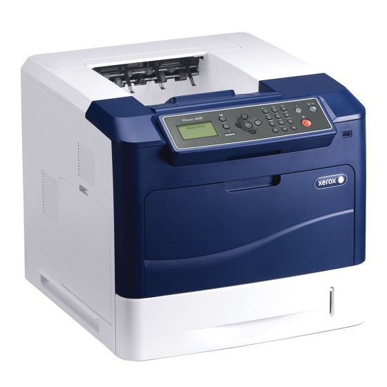
Page 12: Phaser 4600/4620 Overview
Filter Cover Top Cover Printer Stand Toner Cartridge 2000-Sheet Feeder Drum Cartridge Media level Indicator Tray 1 (bypass) 520-Sheet Feeder(s) Tray 1 Media Extension Introduction Revision - Xerox Internal Use Only 5/2011 Phaser 4600/4620 Overview Phaser 4600/4620 Printer Service Manual... -
Page 13: Printer Options
• 200 Pin DDR2 SODIMM • Unbuffered, Non-parity The printer’s Configuration page lists the amount of RAM installed in the printer. Revision - Xerox Internal Use Only Introduction 5/2011 Printer Options Phaser 4600/4620 Printer Service Manual... - Page 14 One 2000-Sheet Feeder (Tray 3) • Up to 2 520-Sheet Feeders (Trays 3, 4) and 1 2000-Sheet Feeder (Tray 5). Figure 4 Optional Mailbox Figure 3 2000-Sheet Feeder Introduction Revision - Xerox Internal Use Only 5/2011 Printer Options Phaser 4600/4620 Printer Service Manual...
-
Page 15: Control Panel Layout
Illuminates when the printer is in Power Saver mode. Press to enter or exit from Power Saver mode. Stop Press to cancel the current activity. Revision - Xerox Internal Use Only Introduction 5/2011 Printer Options, Control Panel Layout Phaser 4600/4620 Printer Service Manual... -
Page 16: Routine Maintenance Items
Drum Cartridge 60,000 cycles Waste Toner Cartridge Provided with new Toner Cartridge Staple Cartridge 15,000 Maintenance Kit (Fuser, Feed Rollers, Transfer 200,000 cycles Roller) Introduction Revision - Xerox Internal Use Only 5/2011 Routine Maintenance Items Phaser 4600/4620 Printer Service Manual... - Page 17 SCP 3 Normal Call Actions ..................... SCP 4 Fault Analysis ...................... SCP 5 Subsystem Maintenance ..................SCP 6 Final Actions ......................SCP 7 Configurations and Options ................. Revision - Xerox Internal Use Only Service Call Procedures 5/2011 Phaser 4600/4620 Printer Service Manual...
- Page 18 Service Call Procedures Revision - Xerox Internal Use Only 5/2011 Phaser 4600/4620 Printer Service Manual...
-
Page 19: Service Call Procedures
Use the Repair procedures to replace the part. Final Checkout • Test the printer to verify the problem is corrected and no new problems arose. Revision - Xerox Internal Use Only Service Call Procedures 5/2011 Service Call Procedures Phaser 4600/4620 Printer Service Manual... -
Page 20: Scp 1 Initial Actions
If this is the first service call to this machine perform SCP 2 First Call Actions, otherwise go to SCP 3 Normal Call Actions. Service Call Procedures Revision - Xerox Internal Use Only 5/2011 SCP 1, SCP 2 Phaser 4600/4620 Printer Service Manual... -
Page 21: Scp 3 Normal Call Actions
Separate System Modules • GP 15 How to Safely Move heavy Modules • GP 16 Machine Lubrication • GP 17 Installation Space Requirements Revision - Xerox Internal Use Only Service Call Procedures 5/2011 SCP 3, SCP 4 Phaser 4600/4620 Printer Service Manual... -
Page 22: Scp 5 Subsystem Maintenance
Plastic parts will deteriorate when unspecified grease and chemicals are used. To avoid dam- age to the printer, use only Rheolube 768 grease. • Rheolube 768 Grease: Part Number 070E00890 Service Call Procedures Revision - Xerox Internal Use Only 5/2011 SCP 4, SCP 5 Phaser 4600/4620 Printer Service Manual... -
Page 23: Scp 6 Final Actions
100k impressions PL 9.10 Item 2 reset. Fuser Total prints after the last HFSI 200k impressions PL 10.10 Item 1 reset. Revision - Xerox Internal Use Only Service Call Procedures 5/2011 SCP 5, SCP 6 Phaser 4600/4620 Printer Service Manual... -
Page 24: Scp 7 Configurations And Options
1200 Class 1200 Class * All configurations have one memory slot supporting a 512 MB DDR2 DIMM, to a maximum 768 MB total. Service Call Procedures Revision - Xerox Internal Use Only 5/2011 SCP 7 Phaser 4600/4620 Printer Service Manual... - Page 25 07-430-00, 07-431-00 Jam in Tray 5 RAP ..............2-29 12-500-00 Full Stack RAP....................2-59 07-500-00 Paper Empty in Tray 1 RAP................2-30 12-605-00 Staples Low RAP ................... 2-60 Revision - Xerox Internal Use Only Status Indicator RAPS 5/2011 Phaser 4600/4620 Printer Service Manual...
- Page 26 17-700-00, 17-710-00 BOOTP Server Error RAP ............2-73 17-800-00, 17-810-00 DHCP Server Error RAP ............. 2-73 17-900-00 802.1X Authentication Error RAP ..............2-74 17-910-00 Firmware Upgrade Fault RAP................ 2-74 Status Indicator RAPS Revision - Xerox Internal Use Only 5/2011 Phaser 4600/4620 Printer Service Manual...
-
Page 27: Top Door Open Rap
Rear Door, PL 28.25 Item 1 MCU Board, PL 3.10 Item 3 Joint Board, PL 9.15 Item 7 Exit Assembly, PL 10.30 Item 25 Revision - Xerox Internal Use Only Status Indicator RAPS 5/2011 01-100-00, 01-102-00 Phaser 4600/4620 Printer Service Manual... -
Page 28: Finisher Door Open Rap
PL 10.30 Item 24 IOT Upper Option Harness, PL 10.30 Item 24 MCU Board, PL 3.10 Item 3 MCU Board, PL 3.10 Item 3 Status Indicator RAPS Revision - Xerox Internal Use Only 5/2011 01-500-00, 01-700-00 Phaser 4600/4620 Printer Service Manual... -
Page 29: Mailbox Rear Door Open Rap
PL 11.30 Item 4 Mailbox Control Board, PL 11.15 Item 1 IOT Upper Option Harness, PL 10.30 Item 24 MCU Board, PL 3.10 Item 3 Revision - Xerox Internal Use Only Status Indicator RAPS 5/2011 01-900-00, 03-100-00, 03-110-00 Phaser 4600/4620 Printer Service Manual... -
Page 30: Mailbox Interface Error Rap
Replace these components in order until the error is corrected. Feeder Board, PL 8.30 Item 7 MCU Board, PL 3.10 Item 3 Status Indicator RAPS Revision - Xerox Internal Use Only 5/2011 03-115-00, 03-120-00, 03-940-00 Phaser 4600/4620 Printer Service Manual... -
Page 31: Tray 4 Communications Fault Rap
PL 8.30 Item 7 Feeder Board, PL 8.30 Item 7 MCU Board, PL 3.10 Item 3 MCU Board, PL 3.10 Item 3 Revision - Xerox Internal Use Only Status Indicator RAPS 5/2011 03-130-00, 03-950-00, 03-140-00, 03-960-00 Phaser 4600/4620 Printer Service Manual... -
Page 32: Tray 6 Communications Fault Rap
Replace these components in order until the error is corrected. HCF Control Board, PL 7.25 Item 18 MCU Board, PL 3.10 Item 3 Status Indicator RAPS Revision - Xerox Internal Use Only 5/2011 03-150-00, 03-965-00, 03-160-00, 03-990-00 Phaser 4600/4620 Printer Service Manual... -
Page 33: Configuration Card Not Present Rap
Replace these components in order until the error is corrected. IP Board, PL 3.10 Item 2 Configuration Card, PL 3.10 Item 6 IP Board, PL 3.10 Item 2 Revision - Xerox Internal Use Only Status Indicator RAPS 5/2011 03-305-00, 03-315-00, 03-325-00 Phaser 4600/4620 Printer Service Manual... -
Page 34: Configuration Card Not Configured Rap
Replace these components in order until the error is corrected. Size Switch, PL 3.10 Item 9 Tray, PL 7.10 Item 23 MCU Board, PL 3.10 Item 3 Status Indicator RAPS Revision - Xerox Internal Use Only 5/2011 03-335-00 , 03-410-00 2-10 Phaser 4600/4620 Printer Service Manual... -
Page 35: Tray 3 Paper Mismatch Rap
Size Switch, PL 3.10 Item 9 Tray, PL 7.10 Item 23 Feeder Board, PL 8.30 Item 7 MCU Board, PL 3.10 Item 3 Revision - Xerox Internal Use Only Status Indicator RAPS 5/2011 03-420-00, 03-430-00 Phaser 4600/4620 Printer Service Manual 2-11... -
Page 36: Tray 5 Paper Mismatch Rap
Size Switch, PL 3.10 Item 9 Tray, PL 7.10 Item 23 Feeder Board, PL 8.30 Item 7 MCU Board, PL 3.10 Item 3 Status Indicator RAPS Revision - Xerox Internal Use Only 5/2011 03-440-00, 03-450-00 2-12 Phaser 4600/4620 Printer Service Manual... -
Page 37: Tray 6 Paper Mismatch Rap
PL 8.30 Item 7 Size Switch, PL 7.25 Item 5 MCU Board, PL 3.10 Item 3 HCF Option Connector, PL 7.25 Item 15 Revision - Xerox Internal Use Only Status Indicator RAPS 5/2011 03-470-00, 03-480-00 Phaser 4600/4620 Printer Service Manual 2-13... -
Page 38: Memory Failure Rap
Remove optional memory, if installed and retest. The error message is displayed. Replace the optional memory using the instructions provided. Replace the IP Board, 3.6. Status Indicator RAPS Revision - Xerox Internal Use Only 5/2011 03-480-00, 03-600-00 2-14 Phaser 4600/4620 Printer Service Manual... -
Page 39: Hard Disk Drive Failure Rap
Replace the Hard Drive using the instructions provided. The error message is displayed. Complete. Complete. Replace the MCU Board, 3.4. Replace the IP Board, 3.6. Revision - Xerox Internal Use Only Status Indicator RAPS 5/2011 03-800-00, 03-970-00 Phaser 4600/4620 Printer Service Manual 2-15... -
Page 40: Tray 2 Lift Error Rap
Replace these components in order until the error is corrected. Tray Replace the MCU Board, 3.4. Tray 2 Level Sensor, PL 8.50 Item 25 MCU Board, REP 3.4 Status Indicator RAPS Revision - Xerox Internal Use Only 5/2011 04-100-00, 04-110-00 2-16 Phaser 4600/4620 Printer Service Manual... -
Page 41: Tray 3 Lift Error Rap
Check the Feeder Upper Option Harness. The harness is undamaged. Repair or replace the harness, 7.31. Replace the Lift Motor, 7.7, then retest. The Lift Motor rotates. Revision - Xerox Internal Use Only Status Indicator RAPS 5/2011 04-110-00, 04-200-00 Phaser 4600/4620 Printer Service Manual... -
Page 42: Tray 4 Lift Error Rap
The error message changes to the new feeder position. Check the IOT Lower Option Harness. The harness is undamaged. Replace the Lower Option Harness, 10.5. Replace the MCU Board, 3.4. Status Indicator RAPS Revision - Xerox Internal Use Only 5/2011 04-200-00, 04-300-00 2-18 Phaser 4600/4620 Printer Service Manual... -
Page 43: Tray 5 Lift Error Rap
Feeder positions. The error message changes to the new feeder position. Check the IOT Lower Option Harness. The harness is undamaged. Replace the Lower Option Harness, 10.5. Replace the MCU Board, 3.4. Revision - Xerox Internal Use Only Status Indicator RAPS 5/2011 04-300-00, 04-400-00 Phaser 4600/4620 Printer Service Manual 2-19... -
Page 44: Main Motor Failure Rap
Final Actions. Replace these components in order until the error is corrected. MCU Board, PL 3.10 Item 3 HVPS, PL 1.10 Item 1 Status Indicator RAPS Revision - Xerox Internal Use Only 5/2011 04-400-00, 04-500-00 2-20 Phaser 4600/4620 Printer Service Manual... -
Page 45: Hcf Lift Error Rap
Remove the IOT, Tray 3 and Tray 4 from the HCF and check the HCF Option Harness, 7.25 Item 15. The harness is undamaged. Replace the harness (). Check the IOT Lower Option Harness. The harness is undamaged. Revision - Xerox Internal Use Only Status Indicator RAPS 5/2011 04-730-00 Phaser 4600/4620 Printer Service Manual... -
Page 46: Rear Fan Failure Rap
PL 9.15 Item 7 Exit Assembly, PL 10.30 Item 25 Reassemble and perform SCP 6 Final Actions. Reassemble and perform SCP 6 Final Actions. Status Indicator RAPS Revision - Xerox Internal Use Only 5/2011 04-810-00, 04-930-00 2-22 Phaser 4600/4620 Printer Service Manual... -
Page 47: Lsu Error Rap
Reassemble and perform SCP 6 Final Actions. Reassemble and perform SCP 6 Final Actions. Reassemble and perform SCP 6 Final Actions. Revision - Xerox Internal Use Only Status Indicator RAPS 5/2011 06-100-00, 06-200-00, 07-110-00 Phaser 4600/4620 Printer Service Manual 2-23... -
Page 48: 07-120-00 Tray 2 Is Open Rap
The Feed Drive Assembly rotates. Replace the Feed Drive Assembly, 4.4. Reassemble and perform SCP 6 Final Actions. Replace the MCU Board, 3.4. Status Indicator RAPS Revision - Xerox Internal Use Only 5/2011 07-120-00, 07-130-00 2-24 Phaser 4600/4620 Printer Service Manual... -
Page 49: Paper Empty At Tray 3 Rap
Replace the MCU Board, 3.4. Reassemble and perform SCP 6 Final Actions. Reassemble and perform SCP 6 Final Actions. Replace the MCU Board, 3.4. Revision - Xerox Internal Use Only Status Indicator RAPS 5/2011 07-210-00, 07-220-00 Phaser 4600/4620 Printer Service Manual 2-25... -
Page 50: Jam In Tray 3 Rap
SCP 6 Final Actions. Feed Assembly, PL 8.40 Item 10 Pick Assembly, PL 8.20 Item 17 Replace the MCU Board, 3.4. Status Indicator RAPS Revision - Xerox Internal Use Only 5/2011 07-230-00, 07-231-00, 07-310-00 2-26 Phaser 4600/4620 Printer Service Manual... -
Page 51: Tray 4 Is Open Rap
Reassemble and perform SCP 6 Final Actions. Replace these components in order until the error is corrected. Feed Assembly, PL 8.40 Item 10 Revision - Xerox Internal Use Only Status Indicator RAPS 5/2011 07-320-00, 07-330-00, 07-331-00 Phaser 4600/4620 Printer Service Manual 2-27... -
Page 52: Paper Empty At Tray 5
Replace the Feeder Board, 7.28. Reassemble and perform SCP 6 Final Actions. Reassemble and perform SCP 6 Final Actions. Replace the MCU Board, 3.4. Status Indicator RAPS Revision - Xerox Internal Use Only 5/2011 07-330-00, 07-331-00, 07-410-00 2-28 Phaser 4600/4620 Printer Service Manual... -
Page 53: Tray 5 Is Open Rap
Reassemble and perform SCP 6 Final Actions. Replace these components in order until the error is corrected. Feed Assembly, PL 8.40 Item 10 Revision - Xerox Internal Use Only Status Indicator RAPS 5/2011 07-420-00, 07-430-00, 07-431-00 Phaser 4600/4620 Printer Service Manual 2-29... -
Page 54: Paper Empty In Tray 1 Rap
Replace the MCU Board, 3.4. Reassemble and perform SCP 6 Final Actions. Reassemble and perform SCP 6 Final Actions. Replace the MCU Board, 3.4. Status Indicator RAPS Revision - Xerox Internal Use Only 5/2011 07-430-00, 07-431-00, 07-500-00 2-30 Phaser 4600/4620 Printer Service Manual... - Page 55 Replace the Feeder Board, 7.28. Reassemble and perform SCP 6 Final Actions. Reassemble and perform SCP 6 Final Actions. Replace the MCU Board, 3.4. Revision - Xerox Internal Use Only Status Indicator RAPS 5/2011 07-510-00, 07-700-00, 07-520-00 Phaser 4600/4620 Printer Service Manual 2-31...
- Page 56 Reassemble and perform SCP 6 Final Actions. Replace these components in order until the error is corrected. Feed Assembly, PL 8.40 Item 10 Status Indicator RAPS Revision - Xerox Internal Use Only 5/2011 07-530-00, 07-531-00, 07-630-00 2-32 Phaser 4600/4620 Printer Service Manual...
- Page 57 7.39, reseat CN3 on the HCF Control Board, then retest. The sensor signal changes. Replace the HCF Control Board, 7.44. Reassemble and perform SCP 6 Final Actions. Revision - Xerox Internal Use Only Status Indicator RAPS 5/2011 07-531-00, 07-630-00, 07-710-00 Phaser 4600/4620 Printer Service Manual 2-33...
- Page 58 7.43), then retest. The signal changes. Remove the IOT and installed Feeders. Check the option harness connec- tions. The harnesses are undamaged. Status Indicator RAPS Revision - Xerox Internal Use Only 5/2011 07-710-00, 07-720-00 2-34 Phaser 4600/4620 Printer Service Manual...
- Page 59 7.39) and reseat CN7 on the HCF Control Board, then retest. The Feed Drive Assembly rotates. Replace the Feed Drive Assembly, 7.47. Revision - Xerox Internal Use Only Status Indicator RAPS 5/2011 07-720-00, 07-730-00, 07-731-00 Phaser 4600/4620 Printer Service Manual...
- Page 60 Replace these components in order until the error is corrected. Registration Roller Assembly, PL 8.45 Item 12 Registration Clutch, PL 4.10 Item 7 Status Indicator RAPS Revision - Xerox Internal Use Only 5/2011 07-730-00, 07-731-00, 08-100-00 2-36 Phaser 4600/4620 Printer Service Manual...
- Page 61 (REP 28.2) and reseat CN12 on the MCU Board, then retest. The Feed Drive Assembly rotates. Replace the Feed Drive Assembly, 4.4. Revision - Xerox Internal Use Only Status Indicator RAPS 5/2011 08-110-00, 08-200-00 Phaser 4600/4620 Printer Service Manual 2-37...
- Page 62 Reassemble and perform SCP 6 Final Actions. Select dC330 code 08-930 to test the Feed Drive. The Feed Drive Assembly rotates (on/ off). Status Indicator RAPS Revision - Xerox Internal Use Only 5/2011 08-200-00, 08-300-00 2-38 Phaser 4600/4620 Printer Service Manual...
- Page 63 Reassemble and perform SCP 6 Final Actions. Select dC330 code 08-940 to test the Feed Drive. The Feed Drive Assembly rotates (on/ off). Revision - Xerox Internal Use Only Status Indicator RAPS 5/2011 08-300-00, 08-400-00 Phaser 4600/4620 Printer Service Manual 2-39...
- Page 64 Reassemble and perform SCP 6 Final Actions. Select dC330 code 08-950 to test the Feed Drive. The Feed Drive Assembly rotates (on/ off). Status Indicator RAPS Revision - Xerox Internal Use Only 5/2011 08-400-00, 08-450-00 2-40 Phaser 4600/4620 Printer Service Manual...
- Page 65 28.3) and reseat CN1 on the Joint Board, then retest. The Fuser Release Drive rotates. Replace the Fuser Release Drive, 10.17. Reassemble and perform SCP 6 Final Actions. Revision - Xerox Internal Use Only Status Indicator RAPS 5/2011 08-450-00, 08-500-00 Phaser 4600/4620 Printer Service Manual 2-41...
- Page 66 The Duplex Drive Assembly rotates. Replace the Duplex Drive Assembly, 10.9. Reassemble and perform SCP 6 Final Actions. Replace the MCU Board, 3.4. Status Indicator RAPS Revision - Xerox Internal Use Only 5/2011 08-500-00, 08-600-00 2-42 Phaser 4600/4620 Printer Service Manual...
- Page 67 The Duplex Drive Assembly rotates. Replace the Duplex Drive Assembly, 10.9. Reassemble and perform SCP 6 Final Actions. Replace the MCU Board, 3.4. Revision - Xerox Internal Use Only Status Indicator RAPS 5/2011 08-610-00, 08-650-00 Phaser 4600/4620 Printer Service Manual 2-43...
- Page 68 Reassemble and perform SCP 6 Final Actions. Select dC330 code 08-960 to test the Feed Drive. The Feed Drive Assembly rotates (on/ off). Status Indicator RAPS Revision - Xerox Internal Use Only 5/2011 08-800-00 2-44 Phaser 4600/4620 Printer Service Manual...
- Page 69 Remove the Right Cover (REP 7.39) and reseat CN9 on the HCF Control Board, then retest. The clutch is engaged. Replace the Feed Clutch, 7.46. Revision - Xerox Internal Use Only Status Indicator RAPS 5/2011 08-850-00 Phaser 4600/4620 Printer Service Manual 2-45...
- Page 70 Replace these components in order until the error is corrected. Drum Cartridge, PL 9.10 Item 1 Main Drive Assembly, PL 4.10 Item 1 MCU Board, PL 3.10 Item 3 Status Indicator RAPS Revision - Xerox Internal Use Only 5/2011 09-003-00, 09-100-00 2-46 Phaser 4600/4620 Printer Service Manual...
- Page 71 Replace these components in order until the error is corrected. Toner Cartridge Drum Cartridge, PL 9.10 Item 1 MCU Board, PL 3.10 Item 3 Revision - Xerox Internal Use Only Status Indicator RAPS 5/2011 09-200-00, 09-220-00, 09-210-00, 09-270-00 Phaser 4600/4620 Printer Service Manual 2-47...
- Page 72 Replace these components in order until the error is corrected. MCU Board, PL 3.10 Item 3 Joint Board, PL 9.15 Item 7 MCU Board, PL 3.10 Item 3 Status Indicator RAPS Revision - Xerox Internal Use Only 5/2011 09-230-00, 09-250-00, 09-240-00 2-48 Phaser 4600/4620 Printer Service Manual...
- Page 73 If the printer is unsuccessful in automatically adjusting image quality, an error appears indicat- Follow procedures in 09-210-00, 09-270-00 to correct the ADC Sensor error. ing the problem. Use the information above to isolate the problem. Revision - Xerox Internal Use Only Status Indicator RAPS 5/2011 09-271-00, 09-290-00 Phaser 4600/4620 Printer Service Manual...
-
Page 74: 09-300-00 Drum Warning Rap
SCP 6 Final Actions. Replace the MCU Board, 9.8. Replace the MCU Board, 9.8. Replace the Drum Cartridge. Replace the Drum Cartridge. Status Indicator RAPS Revision - Xerox Internal Use Only 5/2011 09-300-00, 09-400-00 2-50 Phaser 4600/4620 Printer Service Manual... - Page 75 Replace these components in order until the error is corrected. Joint Board, PL 9.15 Item 7 MCU Board, PL 3.10 Item 3 Revision - Xerox Internal Use Only Status Indicator RAPS 5/2011 09-500-00, 09-508-00 Phaser 4600/4620 Printer Service Manual 2-51...
- Page 76 Replace these components in order until the error is corrected. Waste Toner Cartridge Detect Sensor, PL 9.15 Item 6 Joint Board, PL 9.15 Item 7 MCU Board, PL 3.10 Item 3 Status Indicator RAPS Revision - Xerox Internal Use Only 5/2011 09-589-00, 09-590-00 2-52 Phaser 4600/4620 Printer Service Manual...
- Page 77 PL 3.10 Item 3 Replace the Drum Cartridge. The error message is displayed. Perform SCP 6 Final Actions. Replace the MCU Board, 9.8. Revision - Xerox Internal Use Only Status Indicator RAPS 5/2011 09-591-00, 09-600-00 Phaser 4600/4620 Printer Service Manual 2-53...
- Page 78 Check the Toner Cartridge. The Toner Cartridge is installed correctly and the seal tape is injury. Moving parts can cause injury. removed. Replace the Toner Cartridge with a genuine Xerox cartridge with the proper SKU. The error Remove seal tape if present, then gently agitate the Toner Cartridge and install.
- Page 79 Remove the Transfer Roller and inspect the high voltage contact point. The contact is clean injury. Moving parts can cause injury. and undamaged. Replace the Drum Cartridge with a genuine Xerox cartridge with the proper SKU. The error message is displayed.
-
Page 80: Fuser Thermal Errors Rap
Replace these components in order until the error is corrected. Fuser, PL 10.10 Item 1 Fuser Drive Board, PL 1.15 Item 2 MCU Board, PL 3.10 Item 3 Status Indicator RAPS Revision - Xerox Internal Use Only 5/2011 10-100-00, 10-200-00, 10-300-00, 10-308-00 2-56 Phaser 4600/4620 Printer Service Manual... - Page 81 SCP 6 Final Actions. Reassemble and perform SCP 6 Final Actions. Replace the MCU Board, 3.4. Replace the MCU Board, 3.4. Revision - Xerox Internal Use Only Status Indicator RAPS 5/2011 10-500-00, 10-510-00, 10-700-00, 10-710-00 Phaser 4600/4620 Printer Service Manual 2-57...
- Page 82 Replace these components in order until the error is corrected. IOT Upper Option Harness, PL 10.30 Item 24 MCU Board, PL 3.10 Item 3 Status Indicator RAPS Revision - Xerox Internal Use Only 5/2011 12-100-00, 12-487-00, 12-200-00 2-58 Phaser 4600/4620 Printer Service Manual...
- Page 83 Replace these components in order until the error is corrected. IOT Upper Option Harness, PL 10.30 Item 24 MCU Board, PL 3.10 Item 3 Revision - Xerox Internal Use Only Status Indicator RAPS 5/2011 12-300-00, 12-488-00, 12-489-00, 12-500-00 Phaser 4600/4620 Printer Service Manual...
-
Page 84: Out Of Staples Rap
Replace these components in order until the error is corrected. MCU Board, PL 3.10 Item 3 IOT Upper Option Harness, PL 10.30 Item 24 MCU Board, PL 3.10 Item 3 Status Indicator RAPS Revision - Xerox Internal Use Only 5/2011 12-605-00, 12-610-00, 12-855-00 2-60 Phaser 4600/4620 Printer Service Manual... -
Page 85: Front Jogger Home Fault Rap
IOT Upper Option Harness, PL 10.30 Item 24 MCU Board, PL 3.10 Item 3 MCU Board, PL 3.10 Item 3 Revision - Xerox Internal Use Only Status Indicator RAPS 5/2011 12-715-00, 12-716-00, 12-725-00, 12-726-00 Phaser 4600/4620 Printer Service Manual 2-61... -
Page 86: Support Finger Home Fault Rap
MCU Board, PL 3.10 Item 3 IOT Upper Option Harness, PL 10.30 Item 24 MCU Board, PL 3.10 Item 3 Status Indicator RAPS Revision - Xerox Internal Use Only 5/2011 12-735-00, 12-736-00, 12-750-00, 12-755-00 2-62 Phaser 4600/4620 Printer Service Manual... -
Page 87: Stacker Fault Rap
Replace these components in order until the error is corrected. IOT Upper Option Harness, PL 10.30 Item 24 MCU Board, PL 3.10 Item 3 Revision - Xerox Internal Use Only Status Indicator RAPS 5/2011 12-760-00, 12-770-00, 12-870-00 Phaser 4600/4620 Printer Service Manual... -
Page 88: Jam In Mailbox Entrance Rap
IOT Upper Option Harness, PL 10.30 Item 24 MCU Board, PL 3.10 Item 3 MCU Board, PL 3.10 Item 3 Status Indicator RAPS Revision - Xerox Internal Use Only 5/2011 12-906-00, 12-907-00, 12-910-00, 12-920-00, 12-930-00, 2-64 Phaser 4600/4620 Printer Service Manual... -
Page 89: Mailbox Bin Jam
IOT Upper Option Harness, PL 10.30 Item 24 MCU Board, PL 3.10 Item 3 MCU Board, PL 3.10 Item 3 Revision - Xerox Internal Use Only Status Indicator RAPS 5/2011 12-911-00, 12-921-00, 12-931-00, 12-941-00, 12-912- Phaser 4600/4620 Printer Service Manual 2-65... -
Page 90: Diverter Fault Rap
Replace these components in order until the error is corrected. IOT Upper Option Harness, PL 10.30 Item 24 MCU Board, PL 3.10 Item 3 Status Indicator RAPS Revision - Xerox Internal Use Only 5/2011 12-913-00, 12-923-00, 12-933-00, 12-943-00, 12-915-00 2-66 Phaser 4600/4620 Printer Service Manual... -
Page 91: Upper Diverter Fault Home Rap
IOT Upper Option Harness, PL 10.30 Item 24 MCU Board, PL 3.10 Item 3 MCU Board, PL 3.10 Item 3 Revision - Xerox Internal Use Only Status Indicator RAPS 5/2011 12-925-00, 12-935-00, 12-945-00, 12-955-00 Phaser 4600/4620 Printer Service Manual 2-67... -
Page 92: Email Send Failed Rap
The SMTP server authentication may be supported but not enabled on the device or any 500 Enter the email address and resend the email. code is returned from the mail server. Resend the email. Status Indicator RAPS Revision - Xerox Internal Use Only 5/2011 15-110-00, 15-120-00 2-68... -
Page 93: Network Connection Failure Rap
Check network configuration. • Check account configuration parameters. • Check network configuration. Procedure Cycle system power. Procedure Enter valid user credentials. Revision - Xerox Internal Use Only Status Indicator RAPS 5/2011 15-300-00, 15-310-00, 15-600-00 Phaser 4600/4620 Printer Service Manual 2-69... -
Page 94: Mail Server Connection Failure Rap
Check network configuration. Procedure Check that the DNS server is online. Procedure Check that the SMTP port is open and working correctly. Status Indicator RAPS Revision - Xerox Internal Use Only 5/2011 15-320-00, 15-330-00, 15-700-00 2-70 Phaser 4600/4620 Printer Service Manual... -
Page 95: Ip Address Conflict Rap
Initial Actions • Check DHCP settings. • Check network configuration. • Check network configuration. Procedure Procedure Cycle system power. Cycle system power. Revision - Xerox Internal Use Only Status Indicator RAPS 5/2011 17-100-00, 17-110-00 Phaser 4600/4620 Printer Service Manual 2-71... -
Page 96: Server Not Found Rap
The amber LED flashing indicates that the network is good. Cycle system power. Procedure Reseat the network cable to the IP Board. Status Indicator RAPS Revision - Xerox Internal Use Only 5/2011 17-120-00, 17-200-00 2-72 Phaser 4600/4620 Printer Service Manual... -
Page 97: Bootp Server Error Rap
• Check DHCP settings. • Check network configuration. • Check network configuration. Procedure Procedure Cycle system power. Cycle system power. Revision - Xerox Internal Use Only Status Indicator RAPS 5/2011 17-700-00, 17-710-00, 17-800-00, 17-810-00 Phaser 4600/4620 Printer Service Manual 2-73... -
Page 98: X Authentication Error Rap
Cycle system power and repeat the upgrade procedure. Ensure that the 802.1X EAP type, user name and password for the machine authentication switch and authentication server match. Status Indicator RAPS Revision - Xerox Internal Use Only 5/2011 17-900-00, 17-910-00 2-74... - Page 99 IQS 1 Solid Area Density ....................3-21 IQS 2 Skew ........................3-22 IQS 3 Registration......................3-22 IQS 4 Transparencies ..................... 3-23 IQS 5 Image Area ......................3-23 Revision - Xerox Internal Use Only Image Quality 5/2011 Phaser 4600/4620 Printer Service Manual...
- Page 100 Image Quality Revision - Xerox Internal Use Only 5/2011 Phaser 4600/4620 Printer Service Manual...
-
Page 101: Iq1 Image Quality Entry Rap
Process Streaks Extraneous dark lines/bands in the process direction. IQ10 • Background contamination Scan Streaks Extraneous dark lines/bands in the direction of scan. IQ11 • Ghosting Revision - Xerox Internal Use Only Image Quality 5/2011 Phaser 4600/4620 Printer Service Manual... -
Page 102: Iq2 Deletions (Line, Band, Spots)
Check the media path for dirt, debris, or toner residue. The media path is clean. Clean the media path. Replace the Drum Cartridge and reprint the test print. The image contains spots. Perform SCP 6 Final Actions. Image Quality Revision - Xerox Internal Use Only 5/2011 IQ1, IQ2 Phaser 4600/4620 Printer Service Manual... -
Page 103: Iq3 Unfused Image
Check connections to the Fuser Drive Board. Connections to the Fuser Drive board are secure. Secure the connections between the Fuser Drive Board. Replace the Fuser Drive Board 1.3. Revision - Xerox Internal Use Only Image Quality 5/2011 IQ2, IQ3 Phaser 4600/4620 Printer Service Manual... -
Page 104: Iq4 Resolution
The check points (arrows 1, 2, and 3) meet specification. Replace the following as necessary: • Drum Cartridge PL 9.10 Item 1 • Fuser, PL 10.10 Item 1 Image Quality Revision - Xerox Internal Use Only 5/2011 Phaser 4600/4620 Printer Service Manual... -
Page 105: Iq5 Skewed Image
1. The difference is more than 1 MM or less for single side or 4 MM front to back on double sided prints. The printer is operating within specification. Perform SCP 6 Final actions Check the installation. The printer is on a level surface. Revision - Xerox Internal Use Only Image Quality 5/2011 Phaser 4600/4620 Printer Service Manual... -
Page 106: Iq6 Light Or Undertoned Print
Perform SCP 6 Final Actions. Remove the Transfer Roller and check for surface contamination or excessive wear. The Transfer Roller is good. Replace the Transfer Roller, 9.1. Image Quality Revision - Xerox Internal Use Only 5/2011 Phaser 4600/4620 Printer Service Manual... -
Page 107: Iq7 Spots
Replace the Drum Cartridge and reprint the test print. The image contains spots. Perform SCP 6 Final Actions. Remove the Transfer Roller and check for surface contamination or excessive wear. The Transfer Roller is good. Revision - Xerox Internal Use Only Image Quality 5/2011 Phaser 4600/4620 Printer Service Manual... -
Page 108: Iq8 Blank Print
Install a new Drum Cartridge and reprint the test print. The image is blank. Perform SCP 6 Final Actions. Remove the Transfer Roller and check for surface contamination or excessive wear. The Transfer Roller is good. Image Quality Revision - Xerox Internal Use Only 5/2011 3-10 Phaser 4600/4620 Printer Service Manual... -
Page 109: Iq9 Black Print
Install a new Drum Cartridge and reprint the test print. The image is black. Perform SCP 6 Final Actions. Check HVPS connections to the bias contacts. The connections are secure. Secure the connections. Revision - Xerox Internal Use Only Image Quality 5/2011 Phaser 4600/4620 Printer Service Manual... -
Page 110: Iq10 Process Streaks
Check the media path for dirt, debris, or toner residue. The media path is clean. Clean the media path. Replace the Drum Cartridge and reprint the test print. The image contains vertical streaks. Perform SCP 6 Final Actions. Image Quality Revision - Xerox Internal Use Only 5/2011 IQ10 3-12 Phaser 4600/4620 Printer Service Manual... -
Page 111: Iq11 Scan Streaks
Clean the media path. Remove the Drum Cartridge and clean the electrical contacts. Replace the Drum Cartridge and reprint the test print. The image has horizontal streaks. Perform SCP 6 Final Actions. Revision - Xerox Internal Use Only Image Quality 5/2011 IQ11... -
Page 112: Iq12 Damaged Print
Remove the Fuser. Check for damage or debris on the rollers. The Fuser rollers are good. Clean or replace as necessary; • Heat Roller PL 10.11 • Pressure Roller PL 10.11 • Fuser PL 10.10 Image Quality Revision - Xerox Internal Use Only 5/2011 IQ12 3-14 Phaser 4600/4620 Printer Service Manual... -
Page 113: Iq13 Repeating Defects
Check the media path for dirt, debris, or toner residue. The media path is clean. Clean the media path. Print a test print and compare the defect to the values listed in Table 1. Replace the defective component. Revision - Xerox Internal Use Only Image Quality 5/2011 IQ13 Phaser 4600/4620 Printer Service Manual 3-15... -
Page 114: Iq14 Residual Image
Remove the Drum Cartridge and clean the electrical contacts. Replace the Drum Cartridge and reprint the test print. The residual image defect is still visible. Perform SCP 6 Final Actions. Image Quality Revision - Xerox Internal Use Only 5/2011 IQ14 3-16... -
Page 115: Iq15 Background
Check the image formed on the drum, right after the Transfer Roller. The image is com- • Verify the Toner Cartridge is a Xerox manufactured part with adaquate life remaining. If a pletely transferred to the paper non-Xerox Toner Cartridge is being used, this could be the problem. -
Page 116: Iq16 Uneven Density
Remove the Drum Cartridge, clean the electrical contacts, then print a test print. The image has density defects. Perform SCP 6 Final Actions. Replace the Drum Cartridge and reprint the test print. The image has density defects. Image Quality Revision - Xerox Internal Use Only 5/2011 IQ16 3-18 Phaser 4600/4620 Printer Service Manual... -
Page 117: Iq17 Stains On Print Back
Remove the Fuser. Check for damage or debris on the rollers. The Fuser rollers are good. Clean or replace as necessary; • Heat Roller PL 10.11 • Pressure Roller PL 10.11 Revision - Xerox Internal Use Only Image Quality 5/2011 IQ17 Phaser 4600/4620 Printer Service Manual 3-19... -
Page 118: Iq18 Registration
Replace the HVPS. Check connections between the Laser Unit and IP Board. The connections are secure. Replace the Laser Unit. Replace the MCU Board. Image Quality Revision - Xerox Internal Use Only 5/2011 IQ18, IQ19 3-20 Phaser 4600/4620 Printer Service Manual... -
Page 119: Test Prints
Corrective Action Go to the Image Quality Entry RAP. Figure 1 Test pattern 1, 2 Revision - Xerox Internal Use Only Image Quality 5/2011 Test Prints, IQS 1 Phaser 4600/4620 Printer Service Manual... -
Page 120: Iqs 2 Skew
Tray 1 and 2 12.7± 1.5 12.7± 2.0 241.3±1.5mm Go to the IQ19 Poor Registration RAP. Optional Trays 12.7± 2.0 12.7± 2.5 Image Quality Revision - Xerox Internal Use Only 5/2011 IQS 2, IQS 3 3-22 Phaser 4600/4620 Printer Service Manual... -
Page 121: Iqs 4 Transparencies
IQS 4 Transparencies IQS 5 Image Area Specifications NOTE: Customer must use standard Transparency media (A4, Letter) designed exclusively for Xerox 3R9023. Separate each page after printing. Refer to Figure Specifications Refer to Table Table 1 Registration measurement Registration Specification... - Page 122 Image Quality Revision - Xerox Internal Use Only 5/2011 IQS 4, IQS 5 3-24 Phaser 4600/4620 Printer Service Manual...
- Page 123 REP 7.41 HCF Caster..................... 4-55 REP 10.15 Fuser Heat Roller and Bearings..............4-106 REP 7.42 HCF Reduction Gear Assembly..............4-55 REP 10.16 Fuser Pressure Roller and Bearings............. 4-112 Revision - Xerox Internal Use Only Repairs 5/2011 Phaser 4600/4620 Printer Service Manual...
- Page 124 REP 28.7 Rear Door Fan ....................4-151 REP 28.8 Right Seal Filter ....................4-152 REP 28.9 USB Host Board ..................... 4-153 REP 28.10 Rear Seal Filter..................... 4-153 Repairs Revision - Xerox Internal Use Only 5/2011 Phaser 4600/4620 Printer Service Manual...
-
Page 125: Rep 1.2 Fuser Drive Board
Figure 1 Remove the Fuser Drive Assembly screws Figure 1 Remove the Fuser Drive Board Disconnect 4 connections to the Fuser Drive Assembly, Figure Revision - Xerox Internal Use Only Repairs 5/2011 REP 1.2, REP 1.3 Phaser 4600/4620 Printer Service Manual... -
Page 126: Rep 1.4 Hvps
11. Release the ribbon cable from the guide and remove 1 screw (metal) that secures the guide to the MCU Board bracket, Figure Repairs Revision - Xerox Internal Use Only 5/2011 REP 1.3, REP 1.4 Phaser 4600/4620 Printer Service Manual... - Page 127 Figure 15. Disconnect CN3 from the HVPS and move the Fuser harness to the side, Figure Figure 3 Remove the right side power supply tray screws Revision - Xerox Internal Use Only Repairs 5/2011 REP 1.4 Phaser 4600/4620 Printer Service Manual...
- Page 128 19. Disconnect CN1 and remove 5 screws (metal) that secure the HVPS to the power supply Figure tray, Figure Figure 6 Disconnect the drum bias voltage connector Figure 8 Remove the HVPS Repairs Revision - Xerox Internal Use Only 5/2011 REP 1.4 Phaser 4600/4620 Printer Service Manual...
-
Page 129: Rep 1.5 Smps
11. Release the ribbon cable from the guide and remove 1 screw (metal) that secures the guide to the MCU Board bracket, Figure Figure 3 Remove the right side power supply tray screws Revision - Xerox Internal Use Only Repairs 5/2011 REP 1.5... - Page 130 Figure 15. Disconnect CN3 from the HVPS and move the Fuser harness to the side, Figure Figure 6 Disconnect the drum bias voltage connector Repairs Revision - Xerox Internal Use Only 5/2011 REP 1.5 Phaser 4600/4620 Printer Service Manual...
- Page 131 19. Disconnect CON3, release the harness from the clamp, and remove 4 screws (metal) that secure the SMPS to the power supply tray, Figure Figure 8 Remove the SMPS Revision - Xerox Internal Use Only Repairs 5/2011 REP 1.5 Phaser 4600/4620 Printer Service Manual...
-
Page 132: Rep 1.6 Top Door Interlock Switch
Turn the cover over and release 4 hooks that secure the switches to the cover, Figure Figure 1 Remove the SMPS Fan Figure 1 Remove the Interlock Switch Repairs Revision - Xerox Internal Use Only 5/2011 REP 1.6, REP 1.7 4-10 Phaser 4600/4620 Printer Service Manual... -
Page 133: Rep 2.1 Control Panel Assembly
Release 2 bosses that secure the Top Door to the Top Cover, Figure Figure 1 Release the Control Panel harness Remove 2 screws (plastic) that secure the Top Door hinges to the Top Cover, Figure Revision - Xerox Internal Use Only Repairs 5/2011 REP 2.1 Phaser 4600/4620 Printer Service Manual... - Page 134 Remove 4 screws (plastic) that secure the harness cover to the Top Door, Figure Figure 5 Remove the Control Panel from the Top Door Repairs Revision - Xerox Internal Use Only 5/2011 REP 2.1 4-12 Phaser 4600/4620 Printer Service Manual...
-
Page 135: Rep 2.2 Control Panel Board
Figure 6 Lacing the Control Panel harness Figure 1 Remove the Control Panel Assembly lower cover Remove 7 screws (plastic) that secure the Control Panel Bard to the lower cover, Figure Revision - Xerox Internal Use Only Repairs 5/2011 REP 2.1, REP 2.2... - Page 136 Figure 2 Remove the Control Panel Board Release 2 hooks that secure the LCD screen to the Control Panel Board. Disconnect CN1 and CN3 from the Control Panel Board to remove the LCD screen. Repairs Revision - Xerox Internal Use Only 5/2011 REP 2.2 4-14...
-
Page 137: Rep 3.4 Mcu Board
Figure 1 Remove the MCU Board and bracket. Replacement After removal of the MCU Board, move the MSOK board, located in CN4 at Red arrow in Fig- 1, to the new board. Revision - Xerox Internal Use Only Repairs 5/2011 REP 3.4 Phaser 4600/4620 Printer Service Manual... -
Page 138: Rep 3.5 Ip Board Cage
Remove 2 screws (metal) and slide the IP Cage to the rear to release 2 hooks that secure the cage to the chassis, Figure Repairs Revision - Xerox Internal Use Only 5/2011 REP 3.5 4-16 Phaser 4600/4620 Printer Service Manual... -
Page 139: Rep 3.6 Ip Board
Disconnect 5 connections (CN8, CN10, CN12, CN13, and CN14) to the IP Board and feed the harnesses out the holes provided, Figure Figure 2 Remove the IP Board Cage Revision - Xerox Internal Use Only Repairs 5/2011 REP 3.5, REP 3.6... - Page 140 Figure After removal of the IP Board from the cage, move the Configuration Card, Configuration Card holder and if installed, optional Memory and Hard Drive to the new board. Repairs Revision - Xerox Internal Use Only 5/2011 REP 3.6 4-18...
-
Page 141: Rep 4.1 Main Drive Assembly
Figure 1 Disconnect the Main Drive Assembly Disconnect the USB cable from the Front Cover. Raise the Top Door. Release the top door linkage from the Main Drive Assembly, Figure Revision - Xerox Internal Use Only Repairs 5/2011 REP 4.1 Phaser 4600/4620 Printer Service Manual... -
Page 142: Rep 4.2 Tray 2 Feed Clutch
Release the harnesses from 3 clamps at the top of the MCU Board. Remove 3 screws (metal) that secure the MCU Board bracket to the chassis, Figure Figure 3 Remove main Drive Assembly screws Repairs Revision - Xerox Internal Use Only 5/2011 REP 4.1, REP 4.2 4-20 Phaser 4600/4620 Printer Service Manual... - Page 143 Figure 1 Disconnect the MCU Board Lift the MCU Board bracket to release the tabs and move the board out and right to access the clutch, Figure Revision - Xerox Internal Use Only Repairs 5/2011 REP 4.2 Phaser 4600/4620 Printer Service Manual...
-
Page 144: Rep 4.3 Registration Clutch
Remove the E-ring that secures the clutch to the shaft. Figure 3 Remove the Tray 2 Feed Clutch Figure 1 Remove the Registration Clutch Repairs Revision - Xerox Internal Use Only 5/2011 REP 4.2, REP 4.3 4-22 Phaser 4600/4620 Printer Service Manual... -
Page 145: Rep 4.4 Feed Drive Assembly
4.2. Disconnect P/J53 from the Feed Drive Assembly. Remove 5 screws (Gold, metal) that secure the Feed Drive Assembly. Figure 1 Remove the Feed Drive Assembly Revision - Xerox Internal Use Only Repairs 5/2011 REP 4.4 Phaser 4600/4620 Printer Service Manual... -
Page 146: Rep 4.5 Right Side Chassis Fan
Remove 4 screws (metal) that secure the Laser Unit to the chassis, Figure Figure 1 Remove the Right Side Chassis Fan Figure 1 Remove the Laser Unit Repairs Revision - Xerox Internal Use Only 5/2011 REP 4.5, REP 6.1 4-24 Phaser 4600/4620 Printer Service Manual... -
Page 147: Rep 7.0 Tray 1 Feeder Assembly
Figure Figure 1 Disconnect the Tray 1 Feeder harness from the MCU Board Remove 4 screws (metal) that secure the feeder to the chassis, Figure Revision - Xerox Internal Use Only Repairs 5/2011 REP 7.0 Phaser 4600/4620 Printer Service Manual... -
Page 148: Rep 7.3 Tray 1 Pick-Up Assembly
10. Remove the Tray 1 Feed Clutch, 7.16. 11. Remove 4 screws (plastic) that secure the top of the Feeder Assembly, Figure Figure 3 Feeder Assembly wire routing Repairs Revision - Xerox Internal Use Only 5/2011 REP 7.0, REP 7.3 4-26 Phaser 4600/4620 Printer Service Manual... - Page 149 Check No Paper Sensor actuator operation and position before securing the Tray 1 Feeder Assembly top cover, Figure Figure 1 Remove the Feeder Assembly top screws 12. Remove the Pick Assembly from the Feeder Assembly, Figure Revision - Xerox Internal Use Only Repairs 5/2011 REP 7.3 Phaser 4600/4620 Printer Service Manual 4-27...
-
Page 150: Rep 7.5 Tray 1 Separator Assembly
Rotate the Tray 1 cover to horizontal to release the cover from the Front Cover, Figure Figure 3 Tray 1 No Paper Sensor actuator position Repairs Revision - Xerox Internal Use Only 5/2011 REP 7.3, REP 7.5 4-28 Phaser 4600/4620 Printer Service Manual... - Page 151 Separator Roller Assembly, Figure Figure 3 Remove the Tray 1 guide Remove the screw that secures the Separator Roller Assembly to the feeder, Figure Revision - Xerox Internal Use Only Repairs 5/2011 REP 7.5 Phaser 4600/4620 Printer Service Manual...
-
Page 152: Rep 7.6 Tray 2 Feeder Assembly
Remove 5 screws (2 plastic, 3 metal) that secure the rear support bracket to the chassis. 10. Lift the bracket and rest on the printer chassis, Figure Figure 5 Tray 1 No Paper Sensor actuator position Repairs Revision - Xerox Internal Use Only 5/2011 REP 7.5, REP 7.6 4-30 Phaser 4600/4620 Printer Service Manual... - Page 153 16. Remove the Registration Clutch, 4.3. 17. Remove the Feed Drive Assembly, 4.4. 18. Remove 4 screws (metal) that secure the front support bracket, Figure Revision - Xerox Internal Use Only Repairs 5/2011 REP 7.6 Phaser 4600/4620 Printer Service Manual 4-31...
- Page 154 23. Remove 3 (2 plastic, 1 metal) screws that secure the left side of the Exit Assembly, Figure Figure 4 Remove the left lower tray guide Repairs Revision - Xerox Internal Use Only 5/2011 REP 7.6 4-32 Phaser 4600/4620 Printer Service Manual...
- Page 155 26. Release the feeder harness from the clamp and feed the harness into the Tray 2 cavity, Figure Figure 7 Release the Tray 2 Feeder harness 27. Remove the spring from the Pick-up Assembly, Figure Revision - Xerox Internal Use Only Repairs 5/2011 REP 7.6 Phaser 4600/4620 Printer Service Manual...
- Page 156 Figure 8 Remove the Tray 2 baseplate screws, bearing and spring 28. Remove 2 metal screws that secure the left side of the power supply tray, Figure Repairs Revision - Xerox Internal Use Only 5/2011 REP 7.6 4-34 Phaser 4600/4620 Printer Service Manual...
- Page 157 Figure Perform the removal steps in reverse order. Pay particular attention to chassis alignment fea- tures, bosses and pins, as you install each component. Do not overtighten fasteners in plastic. Revision - Xerox Internal Use Only Repairs 5/2011 REP 7.6...
-
Page 158: Rep 7.7 Tray 2 Lift Motor
Reach into the Tray 2 cavity and remove the gear, Figure Figure 1 Remove the Tray 2 Lift Gear Figure 1 Remove the Tray 2 Lift Motor Repairs Revision - Xerox Internal Use Only 5/2011 REP 7.7, REP 7.8 4-36 Phaser 4600/4620 Printer Service Manual... -
Page 159: Rep 7.15 Tray 1 No Paper Sensor
Remove 4 screws (plastic) that secure the top of the Feeder Assembly., Figure Figure 2 Remove the Tray 1 No Paper Sensor Figure 1 Remove the Feeder Assembly top screws Revision - Xerox Internal Use Only Repairs 5/2011 REP 7.15... -
Page 160: Rep 7.16 Tray 1 Feed Clutch
Remove the fibre retainer that secures the clutch to the shaft, Figure Figure 1 Remove the Separator Roller Figure 1 Remove the Feeder Assembly top screws Repairs Revision - Xerox Internal Use Only 5/2011 REP 7.16, REP 7.20 4-38 Phaser 4600/4620 Printer Service Manual... -
Page 161: Rep 7.21 Tray Separator Clutch
Figure 1 Remove the E-clip that secures the clutch to the shaft and slide the clutch off the shaft, Figure Figure 1 Remove the Separator Clutch Revision - Xerox Internal Use Only Repairs 5/2011 REP 7.21, REP 7.22 Phaser 4600/4620 Printer Service Manual... -
Page 162: Rep 7.23 Tray Media Level Indicator
Remove the indicator from the tray by releasing the hooks from the tray, Figure Figure 1 Remove the Media Level Indicator Figure 1 Remove the Tray 3 Front Cover Repairs Revision - Xerox Internal Use Only 5/2011 REP 7.22, REP 7.23 4-40 Phaser 4600/4620 Printer Service Manual... -
Page 163: Rep 7.24 Feeder Front Cover
Remove 4 screws and lift to release 2 hooks that secure the Front Cover, Figure Figure 1 Remove the Right Cover Figure 1 Remove the Front Cover Revision - Xerox Internal Use Only Repairs 5/2011 REP 7.24, REP 7.25 Phaser 4600/4620 Printer Service Manual... -
Page 164: Rep 7.26 Feeder Left Cover
To install the Left Cover on a 550-Sheet Feeder removed from the system, lower the safety hook into the feeder chassis and with the slider completely forward, replace the cover. Repairs Revision - Xerox Internal Use Only 5/2011 REP 7.26, REP 7.27... -
Page 165: Rep 7.28 Feeder Board
Disconnect P/J83 from the Lift Motor. Figure Remove 4 screws (metal) that secure the Lift Motor to the chassis, Figure Figure 1 Remove the Feeder Board Revision - Xerox Internal Use Only Repairs 5/2011 REP 7.28, REP 7.29 Phaser 4600/4620 Printer Service Manual... -
Page 166: Rep 7.30 Feeder Size Switch
Release the upper hook that secures the switch in the tray cavity. Disconnect P/J86 and remove the switch, Figure Figure 1 Remove the Lift Motor Repairs Revision - Xerox Internal Use Only 5/2011 REP 7.29, REP 7.30 4-44 Phaser 4600/4620 Printer Service Manual... -
Page 167: Rep 7.31 Upper Option Harness
Remove 2 screws that secure the upper harness bracket to the chassis. Figure 1 Remove the Size Switch Remove the harness from the chassis, Figure Revision - Xerox Internal Use Only Repairs 5/2011 REP 7.30, REP 7.31 Phaser 4600/4620 Printer Service Manual... -
Page 168: Rep 7.32 Lower Option Harness
Figure 1 Disconnect the Upper Feeder Harness Remove 2 screws that secure the lower harness bracket to the chassis. Remove the harness from the chassis, Figure Repairs Revision - Xerox Internal Use Only 5/2011 REP 7.31, REP 7.32 4-46 Phaser 4600/4620 Printer Service Manual... -
Page 169: Rep 7.33 Left Side Frame
Remove 7 screws (metal) that secure the left side frame to the chassis, Figure Figure 2 Remove the Upper Option Harness Figure 1 Remove the left side frame Revision - Xerox Internal Use Only Repairs 5/2011 REP 7.32, REP 7.33... -
Page 170: Rep 7.34 Right Side Frame
Figure 2 Remove the right side frame Figure 1 Disconnect the Upper and Lower Option Harness Remove 7 screws (metal) that secure the left side frame to the chassis, Figure Repairs Revision - Xerox Internal Use Only 5/2011 REP 7.34 4-48 Phaser 4600/4620 Printer Service Manual... -
Page 171: Rep 7.35 Feeder No Paper Sensor
Figure Figure 1 Remove the frame rail 11. Remove 10 (metal) and 4 (plastic) screws that secure the cover to the chassis, Figure Revision - Xerox Internal Use Only Repairs 5/2011 REP 7.35 Phaser 4600/4620 Printer Service Manual 4-49... -
Page 172: Rep 7.36 Feeder No Paper Sensor Actuator
Figure 1 Remove the frame rail 11. Remove 10 (metal) and 4 (plastic) screws that secure the cover to the chassis, Figure Repairs Revision - Xerox Internal Use Only 5/2011 REP 7.35, REP 7.36 4-50 Phaser 4600/4620 Printer Service Manual... - Page 173 Figure 2 Remove the top cover 12. Remove the Feed Assembly, 8.46. 13. Turn the assembly over and release the actuator shaft from the Feed Assembly, Figure Revision - Xerox Internal Use Only Repairs 5/2011 REP 7.36 Phaser 4600/4620 Printer Service Manual...
-
Page 174: Rep 7.37 Feeder Level Sensor
Figure Figure 1 Remove the frame rail 11. Remove 10 (metal) and 4 (plastic) screws that secure the cover to the chassis, Figure Repairs Revision - Xerox Internal Use Only 5/2011 REP 7.37 4-52 Phaser 4600/4620 Printer Service Manual... -
Page 175: Rep 7.38 Hcf Rear Cover
Remove 2 screws (metal) that secure the rear cover to the chassis, Figure Figure 3 Remove the Level Sensor Figure 1 Remove the rear cover Revision - Xerox Internal Use Only Repairs 5/2011 REP 7.37, REP 7.38 Phaser 4600/4620 Printer Service Manual... -
Page 176: Rep 7.39 Hcf Right Cover
Slide the left cover to the rear to release the hooks that secure the cover to the chassis, Figure Figure 1 Remove the right cover Figure 1 Remove the left cover Repairs Revision - Xerox Internal Use Only 5/2011 REP 7.39, REP 7.40 4-54 Phaser 4600/4620 Printer Service Manual... -
Page 177: Rep 7.41 Hcf Caster
Figure Pull the affected caster from the base unit, Figure Figure 1 Remove the Reduction Gear Assembly Figure 1 Remove the Caster Revision - Xerox Internal Use Only Repairs 5/2011 REP 7.41, REP 7.42 Phaser 4600/4620 Printer Service Manual 4-55... -
Page 178: Rep 7.43 Hcf Front Door Interlock Switch
Disconnect CN2 and remove 2 screws (metal) that secure the switch to the chassis, Fig- Figure 1 Remove the HCF Control Board Figure 1 Remove the Front Door Interlock Switch Repairs Revision - Xerox Internal Use Only 5/2011 REP 7.43, REP 7.44 4-56 Phaser 4600/4620 Printer Service Manual... -
Page 179: Rep 7.45 Hcf Lift Motor Assembly
Remove the E-clip that secures the clutch to the shaft, Figure sis, Figure Figure 1 Remove the Feed Clutch Figure 1 Remove the Lift Motor Assembly Revision - Xerox Internal Use Only Repairs 5/2011 REP 7.45, REP 7.46 Phaser 4600/4620 Printer Service Manual 4-57... -
Page 180: Rep 7.47 Hcf Feed Drive Assembly
Disconnect CN1 from the feed motor and remove 5 screws (metal) that secure the assembly to the chassis, Figure Figure 1 Remove the Feed Motor Figure 1 Remove the Feed Drive Assembly Repairs Revision - Xerox Internal Use Only 5/2011 REP 7.47, REP 7.48 4-58 Phaser 4600/4620 Printer Service Manual... -
Page 181: Rep 7.49 Hcf Top Plate
Disconnect CN2 from the Jumper Board. Remove the e-clip and pick gear from the HCF pick Assembly. Release the pick-up spring from the pick assembly, Figure Revision - Xerox Internal Use Only Repairs 5/2011 REP 7.49 Phaser 4600/4620 Printer Service Manual... -
Page 182: Rep 8.11 Registration Sensor
Reach into the Tray 2 cavity to release 3 hooks that secure the sensor to the assembly. Disconnect P/J63 from the Registration Sensor, Figure Figure 3 Removing the top plate Figure 1 Remove the Registration Sensor Repairs Revision - Xerox Internal Use Only 5/2011 REP 7.49, REP 8.11 4-60 Phaser 4600/4620 Printer Service Manual... -
Page 183: Rep 8.12 Feed Sensor
Figure 1 Remove the bias cover screws Remove the Pipe Assembly, 9.7. Remove 1 screw (plastic) that secures the Shaft Frame Assembly to the frame, Figure Revision - Xerox Internal Use Only Repairs 5/2011 REP 8.12, REP 8.16 Phaser 4600/4620 Printer Service Manual... - Page 184 Slide the assembly to the left to release the shaft from the Fuser Drive Assembly. 10. Raise the assembly to remove it from the printer, Figure Figure 3 Remove the Shaft Frame Assembly Repairs Revision - Xerox Internal Use Only 5/2011 REP 8.16 4-62 Phaser 4600/4620 Printer Service Manual...
-
Page 185: Rep 8.24 Drum Cartridge Crum Connector
Remove 1 screw that secures the CRUM connector holder to the middle frame assembly. Remove the CRUM connector holder and disconnect the CRUM Connector. Release 2 hooks that secure the connector in the holder, Figure Revision - Xerox Internal Use Only Repairs 5/2011 REP 8.24... -
Page 186: Rep 8.27 Registration Roller Assembly
Figure 1 Remove the Registration Roller Assembly screws 10. Raise the left side of the assembly, then remove the registration roller shaft from the hole in the chassis, Figure Repairs Revision - Xerox Internal Use Only 5/2011 REP 8.27 4-64 Phaser 4600/4620 Printer Service Manual... -
Page 187: Rep 8.31 Registration Sensor Actuator
Figure Figure 1 Remove the envelope guide screws 10. Release 2 clips that secure the actuator cap to the frame and remove the cap, Figure Revision - Xerox Internal Use Only Repairs 5/2011 REP 8.31 Phaser 4600/4620 Printer Service Manual... -
Page 188: Rep 8.32 Feed Sensor Actuator
Figure 11. Release the actuator and spring from the tabs in the frame to remove the actuator. Figure 3 Remove the Registration Sensor Actuator Repairs Revision - Xerox Internal Use Only 5/2011 REP 8.31, REP 8.32 4-66 Phaser 4600/4620 Printer Service Manual... - Page 189 Figure 1 Remove the envelope guide screws 10. Release 2 clips that secure the actuator cap to the frame and remove the cap, Figure Figure 3 Remove the Feed Sensor Actuator Revision - Xerox Internal Use Only Repairs 5/2011 REP 8.32...
-
Page 190: Rep 8.40 Feeder Take Away Clutch
Remove 2 screws (metal) that secure the clutch bracket to the Feed Motor Assembly. Disconnect P/J80 to remove the clutch from the shaft, Figure Figure 1 Remove the Take Away Clutch bracket Repairs Revision - Xerox Internal Use Only 5/2011 REP 8.40 4-68 Phaser 4600/4620 Printer Service Manual... -
Page 191: Rep 8.41 Feeder Feed Clutch
Figure 1 Remove the Feed Clutch Figure 1 Disconnect the Feed Drive Assembly 10. Remove 4 screws (Gold, metal) that secure the assembly to the chassis, Figure Revision - Xerox Internal Use Only Repairs 5/2011 REP 8.41, REP 8.42 Phaser 4600/4620 Printer Service Manual... -
Page 192: Rep 8.43 Feeder Take Away Sensor Actuator
Release the actuator from the tabs to remove, Figure Figure 2 Remove the Feed Drive Assembly Figure 1 Remove the Take Away Sensor Actuator Repairs Revision - Xerox Internal Use Only 5/2011 REP 8.42, REP 8.43 4-70 Phaser 4600/4620 Printer Service Manual... -
Page 193: Rep 8.44 Feeder Take Away Sensor
12. Release the 3 hooks that secure the sensor to the chute, Figure Figure 1 Remove the frame rail 11. Remove 10 (metal) and 4 (plastic) screws that secure the cover to the chassis, Figure Revision - Xerox Internal Use Only Repairs 5/2011 REP 8.44 Phaser 4600/4620 Printer Service Manual... -
Page 194: Rep 8.45 Feeder Take Away Roller
Figure 1 Remove the frame rail 11. Remove 10 (metal) and 4 (plastic) screws that secure the cover to the chassis, Figure Repairs Revision - Xerox Internal Use Only 5/2011 REP 8.44, REP 8.45 4-72 Phaser 4600/4620 Printer Service Manual... - Page 195 Figure 2 Remove the top cover 12. Remove 2 E-clips and 2 bearings, then move the shaft to release it from the chassis, Fig- Figure 3 Remove the Take Away Roller Revision - Xerox Internal Use Only Repairs 5/2011 REP 8.45...
-
Page 196: Rep 8.46 Feeder Feed Assembly
12. Disconnect CN2, CN3, and P/J85, then feed the harnesses into the tray cavity, Figure Figure 1 Remove the frame rail 11. Remove 10 (metal) and 4 (plastic) screws that secure the cover to the chassis, Figure Repairs Revision - Xerox Internal Use Only 5/2011 REP 8.46 4-74 Phaser 4600/4620 Printer Service Manual... - Page 197 Figure 4 Remove the Feed Assembly screws 15. Lift the left side and lower the right side to remove the Feed Assembly from the chassis, Figure Revision - Xerox Internal Use Only Repairs 5/2011 REP 8.46 Phaser 4600/4620 Printer Service Manual...
-
Page 198: Rep 8.47 Hcf Feed Assembly
Remove 4 (plastic) screws that secure the HCF Feed Assembly to the top plate, Figure Figure 5 Remove the Feed Assembly Figure 1 Remove the HCF Feed Assembly Repairs Revision - Xerox Internal Use Only 5/2011 REP 8.46, REP 8.47 4-76 Phaser 4600/4620 Printer Service Manual... -
Page 199: Rep 8.48 Hcf Lift Limit Switch
Disconnect P/J95 and release 2 hooks that secure the sensor to the HCF Feed Assembly, Figure Figure 1 Remove the HCF Take Away Sensor Figure 1 Remove the Lift Limit Switch Revision - Xerox Internal Use Only Repairs 5/2011 REP 8.48, REP 8.49... -
Page 200: Rep 8.50 Hcf No Paper Sensor
Disconnect P/J91 and release 2 hooks that secure the sensor to the HCF Feed Assembly, Figure Figure Figure 1 Remove the HCF Level Sensor Figure 1 Remove the HCF No Paper Sensor Repairs Revision - Xerox Internal Use Only 5/2011 REP 8.50, REP 8.51 4-78 Phaser 4600/4620 Printer Service Manual... -
Page 201: Rep 9.1 Transfer Roller
Figure 1 Remove the transfer roller guide plate Figure 1 Removing the Transfer Roller Remove 2 screws that secure the sensor holder to the frame, Figure Revision - Xerox Internal Use Only Repairs 5/2011 REP 9.1, REP 9.2 Phaser 4600/4620 Printer Service Manual... -
Page 202: Rep 9.3 Waste Toner Cartridge Detect Sensor
Figure Figure 1 Remove the Waste Toner Cartridge Detect Sensor Figure 3 Remove the ADC Sensor from the holder Repairs Revision - Xerox Internal Use Only 5/2011 REP 9.2, REP 9.3 4-80 Phaser 4600/4620 Printer Service Manual... -
Page 203: Rep 9.4 Left Side Chassis Fan
Figure Disconnect P/J26 to remove the sensor, Figure Figure 1 Remove the Left Side Chassis Fan Figure 1 Remove the Environmental Sensor Revision - Xerox Internal Use Only Repairs 5/2011 REP 9.4, REP 9.5 Phaser 4600/4620 Printer Service Manual 4-81... -
Page 204: Rep 9.6 Waste Toner Full Sensor
Remove 1 screw that secures the Waste Toner Full Sensor to the bias contact cover. Disconnect P/J30 from the cover connector. Release the senor harness from the guides to remove the sensor and harness, Figure Repairs Revision - Xerox Internal Use Only 5/2011 REP 9.6 4-82 Phaser 4600/4620 Printer Service Manual... -
Page 205: Rep 9.7 Pipe Assembly
Figure 1 Remove the bias contact cover Remove 2 screws (Gold, metal) that secure the Pipe Assembly. Pull the assembly from the chassis to remove, Figure Revision - Xerox Internal Use Only Repairs 5/2011 REP 9.7 Phaser 4600/4620 Printer Service Manual... -
Page 206: Rep 9.8 Joint Board
Remove 4 screws (metal) that secure the Joint Board to the chassis, Fgiure 1. Figure 1 Remove the Duplex Unit Figure 1 Remove the Interconnect Board screws Repairs Revision - Xerox Internal Use Only 5/2011 REP 9.8, REP 10.1 4-84... -
Page 207: Rep 10.4 Upper Option Harness
Figure Figure 2 Remove the Upper Option Connector Figure 1 Disconnect CN14 from the MCU Board Remove 2 screws (plastic) that secure the connector to the chassis, Revision - Xerox Internal Use Only Repairs 5/2011 REP 10.4 Phaser 4600/4620 Printer Service Manual... -
Page 208: Rep 10.5 Lower Option Harness
Figure 1 Disconnect CN15 from the MCU Board Move the printer so the right side overhangs the edge of the work surface. Remove 2 screws (metal) that secure the connector to the chassis, Repairs Revision - Xerox Internal Use Only 5/2011 REP 10.5 4-86... -
Page 209: Rep 10.6 Exit Assembly
12. Remove 4 screws (metal) that secure the Joint Board to the chassis, Figure Figure 1 Remove the Upper Option Connector screws Remove 5 screws (2 plastic, 3 metal) that secure the rear support bracket to the chassis. Revision - Xerox Internal Use Only Repairs 5/2011 REP 10.6... - Page 210 Figure 3 Remove the Joint Board screws 14. Remove 2 screws (metal) from the left side that secure the Exit Assembly, Figure 13. Disconnect P/J40 from the Exit Assembly, Figure Repairs Revision - Xerox Internal Use Only 5/2011 REP 10.6 4-88 Phaser 4600/4620 Printer Service Manual...
- Page 211 Figure Figure 5 Remove the left side Exit Assembly screws 15. Remove 2 screws (metal) from the right side that secure the Exit Assembly, Figure Revision - Xerox Internal Use Only Repairs 5/2011 REP 10.6 Phaser 4600/4620 Printer Service Manual...
-
Page 212: Rep 10.7 Stack Full Sensor
Figure 7 Remove the Exit Assembly Figure 1 Remove the rear support bracket Remove 4 screws (plastic) that secure the Exit Chute to the chassis. Repairs Revision - Xerox Internal Use Only 5/2011 REP 10.6, REP 10.7 4-90 Phaser 4600/4620 Printer Service Manual... - Page 213 Figure 2 Remove the Exit Chute 11. Disconnect P/J27 from the Stack Full Sensor. 12. Release 3 hooks that secure the sensor to the Exit Chute, Figure Revision - Xerox Internal Use Only Repairs 5/2011 REP 10.7 Phaser 4600/4620 Printer Service Manual...
-
Page 214: Rep 10.8 Fuser Drive Assembly
11. Raise the MCU Board bracket to release the tabs from the chassis and move the board away from the center harness guide, Figure Figure 1 Remove the MCU Board bracket screws Repairs Revision - Xerox Internal Use Only 5/2011 REP 10.8 4-92 Phaser 4600/4620 Printer Service Manual... - Page 215 Fuser Drive Assembly, Figure Figure 4 Remove the center harness guide screws 13. Remove the Fuser Drive spring, Figure Revision - Xerox Internal Use Only Repairs 5/2011 REP 10.8 Phaser 4600/4620 Printer Service Manual 4-93...
- Page 216 15. Remove 4 screws (metal) that secure the Fuser Drive Assembly, Figure Figure 6 Remove the Fuser Drive screws 16. Pull the assembly through the hole in the chassis, Figure Repairs Revision - Xerox Internal Use Only 5/2011 REP 10.8 4-94 Phaser 4600/4620 Printer Service Manual...
-
Page 217: Rep 10.9 Duplex Drive Assembly
Remove 4 screws (Gold, metal) that secure the assembly to the chassis, Figure Figure 7 Remove the Fuser Drive Assembly Figure 1 Remove the Duplex Drive Assembly screws Revision - Xerox Internal Use Only Repairs 5/2011 REP 10.8, REP 10.9... -
Page 218: Rep 10.10 Fuser
Figure 1 Remove the Fuser top cover Figure 1 Remove the Fuser Release 4 hooks and disconnect P/J66 to remove the Thermistor from the Fuser, Figure Repairs Revision - Xerox Internal Use Only 5/2011 REP 10.10, REP 10.11 4-96 Phaser 4600/4620 Printer Service Manual... -
Page 219: Rep 10.12 Fuser Thermostat
Figure 2 Remove the Thermistor Remove 3 screws (2 metal) and (1 plastic) that secure the Fuser top cover, Figure Figure 1 Remove the Fuser top cover Revision - Xerox Internal Use Only Repairs 5/2011 REP 10.11, REP 10.12 Phaser 4600/4620 Printer Service Manual... -
Page 220: Rep 10.13 Fuser Heat Lamp
Figure 2 Remove the Thermostat Figure 1 Remove the Fuser top cover Remove 3 screws (Black, plastic) that secure the duplex cover to the Fuser, Figure Repairs Revision - Xerox Internal Use Only 5/2011 REP 10.12, REP 10.13 4-98 Phaser 4600/4620 Printer Service Manual... - Page 221 Figure 3 Open the lower exit guide Open the lower exit guide, Figure Remove 2 screws (silver, metal) that secure the right cover, Figure Revision - Xerox Internal Use Only Repairs 5/2011 REP 10.13 Phaser 4600/4620 Printer Service Manual 4-99...
- Page 222 Remove 1 screw (Black, plastic) that secures the lamp bracket to the Fuser, Figure Figure 4 Remove the Fuser Right Cover Disconnect T2 from the Thermostat, Figure Figure 6 Remove the right side lamp bracket Repairs Revision - Xerox Internal Use Only 5/2011 REP 10.13 4-100 Phaser 4600/4620 Printer Service Manual...
-
Page 223: Rep 10.14 Fuser Gear
Figure 8 Remove the Heat Lamp Figure 1 Remove the Fuser top cover Remove 3 screws (Black, plastic) that secure the duplex cover to the Fuser, Figure Revision - Xerox Internal Use Only Repairs 5/2011 REP 10.13, REP 10.14 Phaser 4600/4620 Printer Service Manual... - Page 224 Figure 3 Open the lower exit guide Open the lower exit guide, Figure Remove 2 screws (silver, metal) that secure the right cover, Figure Repairs Revision - Xerox Internal Use Only 5/2011 REP 10.14 4-102 Phaser 4600/4620 Printer Service Manual...
- Page 225 Remove 1 screw (Black, plastic) that secures the right lamp bracket to the Fuser, Figure Figure 4 Remove the Fuser Right Cover Disconnect 1 terminal from the Thermostat, Figure Figure 6 Remove the right side lamp bracket Revision - Xerox Internal Use Only Repairs 5/2011 REP 10.14 Phaser 4600/4620 Printer Service Manual 4-103...
- Page 226 11. Remove 1 screw (silver, metal) that secures the thermostat holder to the upper fuser bracket. 12. Shift the thermostat holder right to release the hooks and lift the holder. Repairs Revision - Xerox Internal Use Only 5/2011 REP 10.14 4-104...
- Page 227 Figure 9 Release the thermostat holder Figure 10 Remove the Fuser Gear 13. Remove the Fuser Gear from the Heat Roller. Revision - Xerox Internal Use Only Repairs 5/2011 REP 10.14 Phaser 4600/4620 Printer Service Manual 4-105...
-
Page 228: Rep 10.15 Fuser Heat Roller And Bearings
Remove 3 screws (2 metal) and (1 plastic) that secure the Fuser top cover, Figure Figure 2 Remove the duplex cover Open the lower exit guide, Figure Figure 1 Remove the Fuser top cover Repairs Revision - Xerox Internal Use Only 5/2011 REP 10.15 4-106 Phaser 4600/4620 Printer Service Manual... - Page 229 Figure 3 Open the lower exit guide Disconnect 2 terminals (T1, T2) to the Thermostat, Figure Remove 2 screws (silver, metal) that secure the right cover, Figure Revision - Xerox Internal Use Only Repairs 5/2011 REP 10.15 Phaser 4600/4620 Printer Service Manual...
- Page 230 10. Disconnect the Heat roller thermistors (P/J67 and P/J68) and release the wiring from the thermostat holder guides, Figure Figure 6 Remove the right side lamp bracket Repairs Revision - Xerox Internal Use Only 5/2011 REP 10.15 4-108 Phaser 4600/4620 Printer Service Manual...
- Page 231 11. Remove 1 screw that secures the Thermostat holder to the Fuser and move the holder 12. Remove the Fuser Gear from the Heat Roller, Figure right to release the hooks, Figure Revision - Xerox Internal Use Only Repairs 5/2011 REP 10.15 Phaser 4600/4620 Printer Service Manual...
- Page 232 13. Remove 3 screws (silver, metal with washers) and release 3 hooks that secure the upper exit guide to the Fuser. Open the lower exit guide if closed earlier, Figure Repairs Revision - Xerox Internal Use Only 5/2011 REP 10.15 4-110...
- Page 233 Figure 12 Remove the upper fuser bracket Figure 13 Remove the Heat Roller and Bearings 15. Remove the Heat Roller and Bearings from the Fuser, Figure Revision - Xerox Internal Use Only Repairs 5/2011 REP 10.15 Phaser 4600/4620 Printer Service Manual...
-
Page 234: Rep 10.16 Fuser Pressure Roller And Bearings
Fuser. Remove the Pressure Roller Bearings from the cam followers, Figure Repairs Revision - Xerox Internal Use Only 5/2011 REP 10.16 4-112 Phaser 4600/4620 Printer Service Manual... -
Page 235: Rep 10.17 Fuser Release Drive Assembly
Remove 3 screws (Gold, metal) that secure the Release Drive Assembly to the chassis, Figure Figure 2 Remove the Pressure Roller and Bearings Figure 1 Remove the Fuser Release Drive Assembly Revision - Xerox Internal Use Only Repairs 5/2011 REP 10.16, REP 10.17... -
Page 236: Rep 10.18 Duplex Unit Detect Sensor
Remove the belt from the rear pulley and belt around the front pulley to release the belt from the Duplex Unit, Figure Figure 1 Remove the Duplex Unit Detect Sensor Repairs Revision - Xerox Internal Use Only 5/2011 REP 10.18, REP 10.19 4-114 Phaser 4600/4620 Printer Service Manual... -
Page 237: Rep 10.32 Exit Drive Assembly
Lift the bracket and rest on the printer chassis, Figure Figure 2 Remove the Duplex Unit Timing Belt Figure 1 Remove the rear support bracket Revision - Xerox Internal Use Only Repairs 5/2011 REP 10.19, REP 10.32 Phaser 4600/4620 Printer Service Manual... - Page 238 12. Remove 4 screws (metal) that secure the Exit Drive Assembly to the chassis. 13. Disconnect P/J40 to remove the Exit Drive Assembly, Figure Repairs Revision - Xerox Internal Use Only 5/2011 REP 10.32 4-116 Phaser 4600/4620 Printer Service Manual...
-
Page 239: Rep 11.1 Mailbox Output Tray
Figure Figure 1 Remove the Output Trays Replacement Install the Output trays beginning with the lowest tray. Figure 1 Remove the Left Cover Revision - Xerox Internal Use Only Repairs 5/2011 REP 11.1, REP 11.2 Phaser 4600/4620 Printer Service Manual... -
Page 240: Rep 11.3 Mailbox Right Cover
Remove 1 screw and release 1 hook that secures the cover to the Mailbox, Figure Figure 2 Disconnect the Mailbox connector Figure 1 Remove the right cover Disconnect P/J 1 on the Mailbox Control Board, Repairs Revision - Xerox Internal Use Only 5/2011 REP 11.3 4-118 Phaser 4600/4620 Printer Service Manual... -
Page 241: Rep 11.4 Mailbox Rear Door
Remove 4 (metal) screws that secure the board to the bracket, Figure Figure 1 Remove the rear door Figure 1 Remove the Control Board Revision - Xerox Internal Use Only Repairs 5/2011 REP 11.4, REP 11.5 Phaser 4600/4620 Printer Service Manual... -
Page 242: Rep 11.6 Mailbox Drive Belts
Remove the damaged belt, Figure Figure 1 Remove the mounting bracket Remove 2 screws (plastic) that secure the Control Board bracket to the Mailbox. Repairs Revision - Xerox Internal Use Only 5/2011 REP 11.6 4-120 Phaser 4600/4620 Printer Service Manual... -
Page 243: Rep 11.7 Mailbox Diverter Drive Assemblies
Remove 2 (plastic) screws that secure the assembly to the Mailbox, Figure Figure 3 Mailbox Drive Belt configuration Figure 1 Remove the Diverter Drive Assembly Revision - Xerox Internal Use Only Repairs 5/2011 REP 11.6, REP 11.7 Phaser 4600/4620 Printer Service Manual... -
Page 244: Rep 11.8 Mailbox Diverter Home Position Sensor
Figure 1 Remove the exit gate bracket Remove the actuator and bearing from the mounting bracket, Figure Figure 1 Remove the Diverter Home Position Sensor Repairs Revision - Xerox Internal Use Only 5/2011 REP 11.8, REP 11.9 4-122 Phaser 4600/4620 Printer Service Manual... -
Page 245: Rep 11.10 Mailbox Exit Gate Cam Follower
Remove 1 screw (plastic) that secures the cam gear. Figure Figure 1 Remove the cam gear Remove 2 (plastic) screws that secure the mounting bracket, Figure Revision - Xerox Internal Use Only Repairs 5/2011 REP 11.9, REP 11.10 Phaser 4600/4620 Printer Service Manual... -
Page 246: Rep 11.11 Mailbox Option Harness
Remove 1 (plastic) screw that secures the cam follower to the Mailbox, Figure Figure 1 Remove the option connector Figure 3 Remove the cam follower Replacement Check connector orientation before Mailbox installation. Repairs Revision - Xerox Internal Use Only 5/2011 REP 11.10, REP 11.11 4-124 Phaser 4600/4620 Printer Service Manual... -
Page 247: Rep 11.12 Mailbox Output Tray 4 Stack Full Sensor
Figure 2 Remove the Stack Full Sensor Figure 1 Remove the top cover Disconnect P/J141 from the sensor. Release 4 hooks that secure the sensor to the bracket, Figure Revision - Xerox Internal Use Only Repairs 5/2011 REP 11.12 Phaser 4600/4620 Printer Service Manual... -
Page 248: Rep 11.13 Mailbox Rear Door Interlock Switch
Lift the hook and slide the switch to release the switch. Slide the insulation off the switch terminals and using a small screwdriver, release the har- ness connectors from the switch, Figure Repairs Revision - Xerox Internal Use Only 5/2011 REP 11.13 4-126 Phaser 4600/4620 Printer Service Manual... -
Page 249: Rep 11.14 Mailbox Transport Motor
Remove the right cover, 11.3. Remove 2 screws (metal) and disconnect P/J127 remove the motor, Figure Figure 1 Remove the Transport Motor Revision - Xerox Internal Use Only Repairs 5/2011 REP 11.14, REP 12.1 Phaser 4600/4620 Printer Service Manual 4-127... -
Page 250: Rep 12.2 Finisher Control Board
Remove 5 screws (metal) that secure the board to the bracket, Figure Figure 1 Remove the left cover Figure 1 Remove the Finisher Control Board Repairs Revision - Xerox Internal Use Only 5/2011 REP 12.1, REP 12.2 4-128 Phaser 4600/4620 Printer Service Manual... -
Page 251: Rep 12.3 Finisher Stacker Full Sensor
Disconnect P/J113 from the Stacker Full Sensor and release the 3 hooks to remove the sensor, Figure Figure 1 Remove the Control Board bracket screw, Release the harness clamp and lift the front of the bracket, Figure Revision - Xerox Internal Use Only Repairs 5/2011 REP 12.3 Phaser 4600/4620 Printer Service Manual 4-129... -
Page 252: Rep 12.5 Finisher Transport Drive Assembly
Figure 3 Remove the Stacker Full Sensor Figure 1 Remove the Control Board bracket screw, Release the harness clamp and lift the front of the bracket, Figure Repairs Revision - Xerox Internal Use Only 5/2011 REP 12.3, REP 12.5 4-130 Phaser 4600/4620 Printer Service Manual... - Page 253 Remove the Transport Drive Belt from the motor, Figure Remove 2 screws (metal) that secure the motor bracket to the frame. Disconnect P/J108 from the motor and remove the motor, Figure Revision - Xerox Internal Use Only Repairs 5/2011 REP 12.5 Phaser 4600/4620 Printer Service Manual...
-
Page 254: Rep 12.6 Finisher Exit Gate Sensor
Disconnect P/J116 and release 3 hooks that secure the sensor to the bracket, Figure Figure 4 Remove the Transport Drive Assembly Figure 1 Remove the Exit Gate Sensor Repairs Revision - Xerox Internal Use Only 5/2011 REP 12.5, REP 12.6 4-132 Phaser 4600/4620 Printer Service Manual... -
Page 255: Rep 12.7 Finisher Exit Gate Actuator
Remove 2 (metal) screws that secure the actuator bearing to the bracket. Turn the cam lobe to provide clearance to remove the actuator from the bracket, Figure Figure 1 Remove the exit gate actuator Revision - Xerox Internal Use Only Repairs 5/2011 REP 12.7... -
Page 256: Rep 12.8 Finisher Entrance Drive Belt
Figure 1 Release the bearing from the bracket Move the shaft outwards to release the shaft from the Finisher, then tilt the shaft up to remove, Figure Repairs Revision - Xerox Internal Use Only 5/2011 REP 12.8 4-134 Phaser 4600/4620 Printer Service Manual... -
Page 257: Rep 12.9 Finisher Exit Gate Cam Shaft
Figure 1 Release the bearing from the bracket Move the shaft outwards to release the shaft from the Finisher, then tilt the shaft up to remove, Figure Revision - Xerox Internal Use Only Repairs 5/2011 REP 12.8, REP 12.9 Phaser 4600/4620 Printer Service Manual... -
Page 258: Rep 12.10 Left Tamper Home Position Sensor
Release the hook and disconnect P/J118 to remove the sensor., Figure Figure 2 Remove the shaft from the bracket Figure 1 Remove the Left Tamper Home Position Sensor Repairs Revision - Xerox Internal Use Only 5/2011 REP 12.9, REP 12.10 4-136 Phaser 4600/4620 Printer Service Manual... -
Page 259: Rep 12.11 Finisher Right Cover
Figure 2 Release the option connector and harness Figure 1 Remove the right cover screws Release 2 hooks that secure the option connector cover to the Right Cover and remove the harness through the slot provided, Revision - Xerox Internal Use Only Repairs 5/2011 REP 12.11... -
Page 260: Rep 12.12 Right Tamper Home Position Sensor
Figure 1 Remove the Right Tamper Home Position Sensor Figure 1 Remove the Stapler Remove 2 screws (metal) that secure the switch to the bracket, Figure Repairs Revision - Xerox Internal Use Only 5/2011 REP 12.12, REP 12.13 4-138 Phaser 4600/4620 Printer Service Manual... -
Page 261: Rep 12.14 Stapler Assembly
Figure 3 Remove the harness from the switch Figure 1 Disconnect the Stapler Assembly Remove 2 screws (metal) that secure the Stapler to the bracket, Figure Revision - Xerox Internal Use Only Repairs 5/2011 REP 12.13, REP 12.14 Phaser 4600/4620 Printer Service Manual... -
Page 262: Rep 12.15 Stacker Drive Assembly
Figure 1 Disconnect and remove the Stacker Drive Assembly Replacement Compress the spring and gear to provide clearance to install the Stacker Drive Assembly Repairs Revision - Xerox Internal Use Only 5/2011 REP 12.14, REP 12.15 4-140 Phaser 4600/4620 Printer Service Manual... -
Page 263: Rep 12.16 Staple Interlock Switch
Figure Replacement Install the bearings with the Rear Door closed and hinges in the slots. Figure 2 Remove the switch from the harness Revision - Xerox Internal Use Only Repairs 5/2011 REP 12.16, REP 12.17 Phaser 4600/4620 Printer Service Manual... -
Page 264: Rep 12.18 Finisher Top Cover
Slide the motor to feed the gear through the bracket opening, Figure Figure 1 Remove the top cover Figure 1 Remove the Tamper Motor Repairs Revision - Xerox Internal Use Only 5/2011 REP 12.18, REP 12.19 4-142 Phaser 4600/4620 Printer Service Manual... -
Page 265: Rep 12.20 Finisher Rear Door Open Sensor
Figure 1 Disconnect P/J120 to remove the sensor, Figure Figure 1 Remove the Finisher Exit Sensor Figure 1 Remove the Rear Door Open Sensor Revision - Xerox Internal Use Only Repairs 5/2011 REP 12.20, REP 12.21 Phaser 4600/4620 Printer Service Manual... -
Page 266: Rep 12.22 Finisher Exit Sensor Actuator
Figure 1 Release the Compile Tray harness Remove 4 screws (2 plastic, 2 metal) that secure the assembly to the Finisher. Lift to remove the Compile Tray from the Finisher, Repairs Revision - Xerox Internal Use Only 5/2011 REP 12.22, REP 12.23 4-144... -
Page 267: Rep 12.24 Stacker Shield Assembly
Figure 2 Remove the Compile Tray Assembly Figure 1 Remove 4 screws of the left side Remove 3 screws (1 metal, 2 plastic) that secure the Stapler Assembly to the Finisher, Figure Revision - Xerox Internal Use Only Repairs 5/2011 REP 12.23, REP 12.24... - Page 268 Figure 2 Remove, but do not disconnect the Stapler Assembly Figure 3 Remove the Stacker Shield Assembly Remove 3 screws (plastic) that secure the Stacker Shield Assembly to the Finisher, Fig- Repairs Revision - Xerox Internal Use Only 5/2011 REP 12.24 4-146 Phaser 4600/4620 Printer Service Manual...
-
Page 269: Rep 28.1 Ip Board Cover
Slide the cover to the rear to release 6 hooks to remove the cover, Figure Figure 1 Remove the IP Board Cover Figure 1 Remove the Right Cover Revision - Xerox Internal Use Only Repairs 5/2011 REP 28.1, REP 28.2... -
Page 270: Rep 28.3 Left Cover
Remove 2 screws (metal) that secure the cover to the chassis. Slide the cover to the rear to release 6 hooks to remove the cover, Figure Figure 1 Remove the Left Cover Repairs Revision - Xerox Internal Use Only 5/2011 REP 28.3 4-148 Phaser 4600/4620 Printer Service Manual... -
Page 271: Rep 28.4 Front Cover
Position the front of the printer at the edge of the work surface and tilt the cover outward at the bottom, then lower the cover to release the bosses at the top, Figure Figure 1 Remove the Front Cover Revision - Xerox Internal Use Only Repairs 5/2011 REP 28.4... -
Page 272: Rep 28.5 Top Cover
Remove the option panel and raise the top door to remove 4 screws (metal). Release 2 hooks that secure the cover to the chassis, Figure Repairs Revision - Xerox Internal Use Only 5/2011 REP 28.5 4-150 Phaser 4600/4620 Printer Service Manual... -
Page 273: Rep 28.6 Rear Door
Figure 1 Remove the duplex chute Figure 1 Remove the Rear Door Disconnect P/J28 and release 4 hooks that secure the Fan to the door, Figure Revision - Xerox Internal Use Only Repairs 5/2011 REP 28.6, REP 28.7 Phaser 4600/4620 Printer Service Manual... -
Page 274: Rep 28.8 Right Seal Filter
Release the hook that secures the filter cover to the Right Cover and remove the filter, Figure Figure 2 Remove the Rear Door fan Figure 1 Remove the Right Seal Filter Repairs Revision - Xerox Internal Use Only 5/2011 REP 28.7, REP 28.8 4-152 Phaser 4600/4620 Printer Service Manual... -
Page 275: Rep 28.9 Usb Host Board
Remove 2 screws (plastic) that secure the USB Host Board to the holder, Figure Figure 1 Remove the Rear Seal Filter Figure 1 Remove the USB Host Board Revision - Xerox Internal Use Only Repairs 5/2011 REP 28.9, REP 28.10... - Page 276 Repairs Revision - Xerox Internal Use Only 5/2011 REP 28.9, REP 28.10 4-154 Phaser 4600/4620 Printer Service Manual...
- Page 277 PL 10.30 Exit Assembly ....................5-30 PL 11 - Sorting PL 11.10 Mailbox Covers ....................5-31 PL 11.15 Mailbox Control Board ..................5-32 PL 11.20 Mailbox Drive Belts ..................5-33 Revision - Xerox Internal Use Only Parts Lists 5/2011 Phaser 4600/4620 Printer Service Manual...
- Page 278 Serial Number Prefixes XLTnnnnnn - Phaser 4600 (110 VAC) XLTnnnnnn - Phaser 4600 (110 VAC) XLVnnnnnn - Phaser 4620 (220 VAC) XLWnnnnnn - Phaser 4620 (220 VAC) Table 1 Option and Accessory Part Numbers Iten Service Part Number Sales Part Number...
-
Page 279: Pl 1.10 Hvps
HVPS insulation sheet (P/O PL 1.10 Item 6) – Fuser connector (P/O PL 1.10 Item – HVPS assembly (Not Spared) – Bottom fuser bracket (Not Spared) Revision - Xerox Internal Use Only Parts Lists 5/2011 PL 1.10 Phaser 4600/4620 Printer Service Manual... -
Page 280: Pl 1.15 Fuser Drive Board Assembly
– Fan duct (Not Spared) 001N00525 Fuser drive board assembly (110V) (REP 1.3) – 140N63538 Fuser drive board assembly (220V) (REP 1.3) 127N07584 Fan-DC Parts Lists Revision - Xerox Internal Use Only 5/2011 PL 1.15 Phaser 4600/4620 Printer Service Manual... -
Page 281: Pl 2.10 Control Panel
– LCD screen (P/O PL 2.10 Item 1) – Rubber stop (P/O PL 2.10 Item 1) – Number keys (P/O PL 2.10 Item 1) Revision - Xerox Internal Use Only Parts Lists 5/2011 PL 2.10 Phaser 4600/4620 Printer Service Manual... -
Page 282: Pl 3.10 Main Pwb's
Ribbon cable 120K03640 Wireless I/F option (not shown) NOTE: Tray 2 size switch is not spared but available as part of the 520-Sheet Feeder (050K74180). Parts Lists Revision - Xerox Internal Use Only 5/2011 PL 3.10 Phaser 4600/4620 Printer Service Manual... -
Page 283: Pl 4.10 Main Drives
Tray 2 lift motor (REP 7.7) 007N01665 Tray 2 lift gear (REP 7.8) – Lift motor housing (Not Spared) – Spring (Not Spared) 007N01658 Pick-up drive Revision - Xerox Internal Use Only Parts Lists 5/2011 PL 4.10 Phaser 4600/4620 Printer Service Manual... -
Page 284: Pl 6.10 Laser Unit
PL 6.10 Laser Unit Item Part Description 122N00292 Laser unit (4600) (REP 6.1) – 122N00293 Laser unit (4620) (REP 6.1) Parts Lists Revision - Xerox Internal Use Only 5/2011 PL 6.10 Phaser 4600/4620 Printer Service Manual... -
Page 285: Pl 7.10 Paper Tray (Tray 2 & Optional Feeder)
Pick-up idle gear (P/O PL 7.10 Item – Tray guide roller (P/O PL 7.10 Item – Media level indicator (P/O PL 7.10 Item 23) (REP 7.23) 050N00562 Tray assembly Revision - Xerox Internal Use Only Parts Lists 5/2011 PL 7.10 Phaser 4600/4620 Printer Service Manual... -
Page 286: Pl 7.15 Optional Feeder Main Covers
Right cover (Not Spared) (REP 7.25) – Clutch cover (Not Spared) NOTE: Order the entire 520-Sheet Feeder using Service part number 050K74180 or Sales part number 097N01874. Parts Lists Revision - Xerox Internal Use Only 5/2011 PL 7.15 5-10 Phaser 4600/4620 Printer Service Manual... -
Page 287: Pl 7.20 Hcf Covers
Front cover dummy – Retard cover (Not Spared) NOTE: Order the entire 2000-Sheet Feeder using Service part number 059K77920 or Sales part number 097N01875. Revision - Xerox Internal Use Only Parts Lists 5/2011 PL 7.20 Phaser 4600/4620 Printer Service Manual... -
Page 288: Pl 7.25 Hcf Assembly
7.43) (see NOTE) 140N63395 Jumper board – Feed sensor (P/O ) (see NOTE) NOTE: The component control codes are dependent on the machine configuration. Parts Lists Revision - Xerox Internal Use Only 5/2011 PL 7.25 5-12 Phaser 4600/4620 Printer Service Manual... -
Page 289: Pl 8.10 Tray 1 Feeder Assembly
8.10 Item 14) (REP 7.16) – Bearing (P/O PL 8.10 Item 14) – Actuator arm (P/O PL 8.10 Item 14) 038N00539 Tray 1 feeder assembly (REP 7.0) Revision - Xerox Internal Use Only Parts Lists 5/2011 PL 8.10 Phaser 4600/4620 Printer Service Manual 5-13... -
Page 290: Pl 8.15 Tray 2 Pick-Up Assembly
Tray up limit switch (P/O PL 8.15 Item 21) 130N01628 Duplex feed sensor (Q08-700)/ Registration sensor (Q07-250)/ No paper sensor (Q07-210) – Not Used 001N00527 Feed assembly Parts Lists Revision - Xerox Internal Use Only 5/2011 PL 8.15 5-14 Phaser 4600/4620 Printer Service Manual... -
Page 291: Pl 8.20 Optional Feeder Pick-Up Assembly
NOTE: Order the entire 520-Sheet Feeder using Service part number 050K74180 or Sales part number 097N01874 NOTE: The component control codes are dependent on the machine configuration. Revision - Xerox Internal Use Only Parts Lists 5/2011 PL 8.20 Phaser 4600/4620 Printer Service Manual... -
Page 292: Pl 8.25 Hcf Pick-Up Assembly
– Bearing (P/O PL 8.25 Item 16) – Feed assembly (REP 8.47) NOTE: The component control codes are dependent on the machine configuration. Parts Lists Revision - Xerox Internal Use Only 5/2011 PL 8.25 5-16 Phaser 4600/4620 Printer Service Manual... -
Page 293: Pl 8.30 Optional Feeder Main Drives
Upper option harness (Not Spared) (REP 7.31) – Lower option harness (Not Spared) (REP 7.32) NOTE: The component control codes are dependent on the machine configuration. Revision - Xerox Internal Use Only Parts Lists 5/2011 PL 8.30 Phaser 4600/4620 Printer Service Manual 5-17... -
Page 294: Pl 8.35 Optional Feeder Lift Assembly
Lift motor bracket (Not Spared) – Swing housing (Not Spared) – Lift gear (Not Spared) NOTE: The component control codes are dependent on the machine configuration. Parts Lists Revision - Xerox Internal Use Only 5/2011 PL 8.35 5-18 Phaser 4600/4620 Printer Service Manual... -
Page 295: Pl 8.40 Optional Feeder Feed Assembly
8.46) NOTE: The component control codes are dependent on the machine configuration. The code for tray 6 was not known at time of publication. Revision - Xerox Internal Use Only Parts Lists 5/2011 PL 8.40 Phaser 4600/4620 Printer Service Manual... -
Page 296: Pl 8.45 Registration Roller Assembly
Spring (P/O PL 8.45 Item 12) – Bearing (P/O PL 8.45 Item 12) – Bearing (bronze) (P/O PL 8.45 Item 105N02192 Registration roller assembly (REP 8.27) Parts Lists Revision - Xerox Internal Use Only 5/2011 PL 8.45 5-20 Phaser 4600/4620 Printer Service Manual... -
Page 297: Pl 8.50 Middle Frame Assembly
Registration sensor actuator (P/O PL 8.50 Item 28) (REP 8.32) – Middle frame assembly (Not Spared) – ADC sensor (REP 9.2) (Not Spared) Revision - Xerox Internal Use Only Parts Lists 5/2011 PL 8.50 Phaser 4600/4620 Printer Service Manual 5-21... -
Page 298: Pl 8.55 Upper Frame Assembly
Eraser board (P/O PL 8.55 Item 9) – Slide B roller (P/O PL 8.55 Item 9) – Spring (P/O PL 8.55 Item 9) – Upper frame assembly (Not Spared) Parts Lists Revision - Xerox Internal Use Only 5/2011 PL 8.55 5-22 Phaser 4600/4620 Printer Service Manual... -
Page 299: Pl 9.10 Drum Cartridge
DMO std toner cartridge (13K) – 106R01535 NA/XE Hi-Cap toner cartridge (30K) – 106R01536 DMO Hi-Cap toner cartridge (30K) – 106R01532 Metered/PagePack Hi-Cap toner cartridge Revision - Xerox Internal Use Only Parts Lists 5/2011 PL 9.10 Phaser 4600/4620 Printer Service Manual 5-23... -
Page 300: Pl 9.15 Waste Toner
Waste toner cartridge detect sensor (REP 9.3) 140N63465 Joint board (REP 9.8) – Environmental sensor (Not Spared) (REP 9.5) – Sensor holder (Not Spared) Parts Lists Revision - Xerox Internal Use Only 5/2011 PL 9.15 5-24 Phaser 4600/4620 Printer Service Manual... -
Page 301: Pl 10.10 Fuser Assembly (1 Of 2)
PL 10.10 Fuser Assembly (1 of 2) Item Part Description 126N00339 Fuser assembly (110V) (REP 10.10) – 126N00340 Fuser assembly (220V) (REP 10.10) – Thumbscrew (Not Spared) Revision - Xerox Internal Use Only Parts Lists 5/2011 PL 10.10 Phaser 4600/4620 Printer Service Manual 5-25... -
Page 302: Pl 10.11 Fuser Assembly (2 Of 2)
Lower fuser exit guide assembly (REF: PL 10.20) – Connector (P/O PL 10.10 Item 1) 130N01628 Fuser exit sensor (Q08-600)/ Fuser home sensor (Q10-910) Parts Lists Revision - Xerox Internal Use Only 5/2011 PL 10.11 5-26 Phaser 4600/4620 Printer Service Manual... -
Page 303: Pl 10.15 Upper Fuser Bracket Assembly
Thermostat holder (Not Spared) 130N01531 Thermistor NTC (REP 10.11) – Thermostat (Not Spared) (REP 10.12) 130N01615 Thermistor NTC (side) 130N01614 Thermistor NTC (center) Revision - Xerox Internal Use Only Parts Lists 5/2011 PL 10.15 Phaser 4600/4620 Printer Service Manual 5-27... -
Page 304: Pl 10.20 Lower Fuser Exit Guide Assembly
Fuser exit sensor actuator (Not Spared) – Actuator spring (Not Spared) – Upper fuser exit roller (Not Spared) – Duplex exit gear (Not Spared) Parts Lists Revision - Xerox Internal Use Only 5/2011 PL 10.20 5-28 Phaser 4600/4620 Printer Service Manual... -
Page 305: Pl 10.25 Duplex Unit Assembly
ELA unit roller 1 (P/O PL 10.25 Item – ELA unit roller 2 (P/O PL 10.25 Item 130N01628 Duplex unit detect sensor (REP 10.18) 022N02484 Duplex unit assembly (REP 10.1) Revision - Xerox Internal Use Only Parts Lists 5/2011 PL 10.25 Phaser 4600/4620 Printer Service Manual 5-29... -
Page 306: Pl 10.30 Exit Assembly
Duplex roller (P/O PL 10.30 Item 007N01660 Exit drive assembly (REP 10.32) – Upper option connector (Not Spared) (REP 10.4) 022N02483 Exit assembly (REP 10.6) Parts Lists Revision - Xerox Internal Use Only 5/2011 PL 10.30 5-30 Phaser 4600/4620 Printer Service Manual... -
Page 307: Pl 11.10 Mailbox Covers
Connector cover (Not Spared) – Base plate (Not Spared) NOTE: Order the entire Mailbox using Service part number 050K74190 or Sales part number 097N01877. Revision - Xerox Internal Use Only Parts Lists 5/2011 PL 11.10 Phaser 4600/4620 Printer Service Manual... -
Page 308: Pl 11.15 Mailbox Control Board
Control board (REP 11.5) – Control board bracket (Not Spared) – Mounting bracket (Not Spared) – Mailbox option harness (Not Spared) (REP 11.11) Parts Lists Revision - Xerox Internal Use Only 5/2011 PL 11.15 5-32 Phaser 4600/4620 Printer Service Manual... -
Page 309: Pl 11.20 Mailbox Drive Belts
(REP 11.14) – Grounding strip (Not Spared) – Motor bracket (Not Spared) 023N01282 Primary drive belt (REP 11.6) 023N01281 Drive belt (REP 11.6) Revision - Xerox Internal Use Only Parts Lists 5/2011 PL 11.20 Phaser 4600/4620 Printer Service Manual 5-33... -
Page 310: Pl 11.25 Mailbox Diverter Assembly
– Exit gate actuator (Not Spared) (REP 11.9) – Mounting bracket (Not Spared) – Bearing (Not Spared) – Cam follower spring (Not Spared) Parts Lists Revision - Xerox Internal Use Only 5/2011 PL 11.25 5-34 Phaser 4600/4620 Printer Service Manual... -
Page 311: Pl 11.30 Mailbox Top Stacker Assembly
Stack full sensor assembly (Not Spared) – Output tray 1 stack full sensor (Q12-910) (Not Spared) (REP 11.12) – Sensor bracket (Not Spared) Revision - Xerox Internal Use Only Parts Lists 5/2011 PL 11.30 Phaser 4600/4620 Printer Service Manual 5-35... -
Page 312: Pl 11.35 Mailbox Actuator Shield Assembly
Spring guide (Not Spared) – Feed guide (Not Spared) – Static eliminator (Not Spared) – Stacker full actuator (Not Spared) – Harness (Not Spared) Parts Lists Revision - Xerox Internal Use Only 5/2011 PL 11.35 5-36 Phaser 4600/4620 Printer Service Manual... -
Page 313: Pl 11.40 Mailbox Base Assembly
Spring (paper path) (Not Spared) – Harness (Not Spared) NOTE: Order the entire Mailbox using Service part number 050K74190 or Sales part number 097N01877. Revision - Xerox Internal Use Only Parts Lists 5/2011 PL 11.40 Phaser 4600/4620 Printer Service Manual... -
Page 314: Pl 12.10 Finisher Covers
Bearing (Not Spared) – Top cover (Not Spared) (REP 12.18) NOTE: Order the entire Finisher using Service part number 059K77910 or Sales part number 097N01876. Parts Lists Revision - Xerox Internal Use Only 5/2011 PL 12.10 5-38 Phaser 4600/4620 Printer Service Manual... -
Page 315: Pl 12.15 Finisher Control Board
Description – Control board bracket (Not Spared) (REP 12.3) 140N63471 Control board (REP 12.2) – Stacker full sensor (Q12-845) (Not Spared) (REP 12.3) Revision - Xerox Internal Use Only Parts Lists 5/2011 PL 12.15 Phaser 4600/4620 Printer Service Manual 5-39... -
Page 316: Pl 12.20 Finisher Stacker Shield Assembly
– Guide roll (P/O PL 12.20 Item 1) NOTE: Order the entire Finisher using Service part number 059K77910 or Sales part number 097N01876. Parts Lists Revision - Xerox Internal Use Only 5/2011 PL 12.20 5-40 Phaser 4600/4620 Printer Service Manual... -
Page 317: Pl 12.25 Finisher Stacker Drive Assembly
– Securing bracket (P/O PL 12.25 Item 1) NOTE: Order the entire Finisher using Service part number 059K77910 or Sales part number 097N01876. Revision - Xerox Internal Use Only Parts Lists 5/2011 PL 12.25 Phaser 4600/4620 Printer Service Manual 5-41... -
Page 318: Pl 12.30 Finisher Compile Tray Eject Assembly
825)/Stacker top sensor (Q12-840) (P/O PL 12.30 Item 1) NOTE: Order the entire Finisher using Service part number 059K77910 or Sales part number 097N01876. Parts Lists Revision - Xerox Internal Use Only 5/2011 PL 12.30 5-42 Phaser 4600/4620 Printer Service Manual... -
Page 319: Pl 12.35 Finisher Compile Tray Assembly
Left tamper motor (MOT12-320) (P/ O PL 12.35 Item 1) (REP 12.19) NOTE: Order the entire Finisher using Service part number 059K77910 or Sales part number 097N01876. Revision - Xerox Internal Use Only Parts Lists 5/2011 PL 12.35 Phaser 4600/4620 Printer Service Manual... -
Page 320: Pl 12.40 Finisher Transport Drive Assembly
12.40 Item 1) (REP 12.22) – Inner rear cover (P/O PL 12.40 Item 023N01284 Rear drive belt – Ground strip (P/O PL 12.40 Item 1) Parts Lists Revision - Xerox Internal Use Only 5/2011 PL 12.40 5-44 Phaser 4600/4620 Printer Service Manual... -
Page 321: Pl 12.45 Finisher Stapler Assembly
Stapler (P/O PL 12.45 Item 1) – Staple cartridge door interlock switch (S12-870) (Not Spared) (REP 12.13) – Staple interlock switch (S12-890) (Not Spared) (REP 12.16) Revision - Xerox Internal Use Only Parts Lists 5/2011 PL 12.45 Phaser 4600/4620 Printer Service Manual 5-45... -
Page 322: Pl 28.10 Main Covers
(REP 28.5) – Right fan cover (Not Spared) – Option cover (Not Spared) 035N00428 Right seal filter – Rear support bracket (Not Spared) Parts Lists Revision - Xerox Internal Use Only 5/2011 PL 28.10 5-46 Phaser 4600/4620 Printer Service Manual... -
Page 323: Pl 28.15 Top Cover Assembly
Top door (P/O PL 28.15 Item 9) – Exit gate actuator (P/O PL 28.15 Item 9) – Stacker guide (P/O PL 28.15 Item 002N02982 Top cover assembly Revision - Xerox Internal Use Only Parts Lists 5/2011 PL 28.15 Phaser 4600/4620 Printer Service Manual 5-47... -
Page 324: Pl 28.20 Front Cover Assembly
Tray 1 extension tray (P/O PL 28.20 Item 1) – USB host holder (P/O PL 28.20 Item 1) 140N63464 USB host board (REP 28.9) Parts Lists Revision - Xerox Internal Use Only 5/2011 PL 28.20 5-48 Phaser 4600/4620 Printer Service Manual... -
Page 325: Pl 28.25 Rear Door Assembly
Damper pad (P/O PL 28.15 Item 1) – Female bracket (P/O PL 28.15 Item – Rear door switch (Q01-300) (P/O PL 28.15 Item 1) Revision - Xerox Internal Use Only Parts Lists 5/2011 PL 28.25 Phaser 4600/4620 Printer Service Manual 5-49... -
Page 326: Supplies, Options And Accessories
Duplex Unit 022N02484 097N01923 Memory Upgrade 128K01770 097N01878 160MB Hard Disk 007N01651 097N01879 Wireless Network Adaptor 120K03640 097N01880 Stand 078K00870 097N01916 Parts Lists Revision - Xerox Internal Use Only 5/2011 Supplies, Options and Accessories 5-50 Phaser 4600/4620 Printer Service Manual... - Page 327 GP 22 Environmental Data ..................... 6-26 dC131 NVM Read/Write....................6-26 dC132 NVM Reset ......................6-29 dC305 UI Test ......................... 6-29 dC330 Component Control ..................... 6-30 dC612 Print Test Pattern....................6-33 Revision - Xerox Internal Use Only General Procedures/Information 5/2011 Phaser 4600/4620 Printer Service Manual...
- Page 328 General Procedures/Information Revision - Xerox Internal Use Only 5/2011 Phaser 4600/4620 Printer Service Manual...
-
Page 329: Gp 1 Diagnostics Entry And Exit
Press the Menu button. Select Information and press OK. Select Firmware Versions and press OK. Wait approximately 30 seconds as the traces are transferred to the thumbdrive. Revision - Xerox Internal Use Only General Procedures/Information 5/2011 GP 1, GP 2... -
Page 330: Gp 3 System Administration Tools
GP 3 System Administration Tools Figure 1 Customer menu map 1 of 2 General Procedures/Information Revision - Xerox Internal Use Only 5/2011 GP 3 Phaser 4600/4620 Printer Service Manual... - Page 331 Figure 2 Customer menu map 2 of 2 Revision - Xerox Internal Use Only General Procedures/Information 5/2011 GP 3 Phaser 4600/4620 Printer Service Manual...
-
Page 332: Gp 4 Reports
After the firmware has been upgraded, check that the correct version appears on the Con- figuration page. Refer to GP 4 Reports. General Procedures/Information Revision - Xerox Internal Use Only 5/2011 GP 4, GP 5 Phaser 4600/4620 Printer Service Manual... -
Page 333: Gp 6 Electrostatic Discharge Prevention
Boards (PCB’s). Power Consumption at Rated Voltage • Printing: 550 W Input • Idle: 33 W • Power Saver: 11 W Revision - Xerox Internal Use Only General Procedures/Information 5/2011 GP 6, GP 7 Phaser 4600/4620 Printer Service Manual... -
Page 334: Gp 8 General Disassembly Precautions
Do not overtighten. If a new thread is cut, the plastic component will lose the ability to hold the screw. This also applies to metal components. General Procedures/Information Revision - Xerox Internal Use Only 5/2011 GP 8 Phaser 4600/4620 Printer Service Manual... -
Page 335: Gp 9 Service Menu Map
GP 9 Service Menu Map Figure 1 Service menu map (1/3) Revision - Xerox Internal Use Only General Procedures/Information 5/2011 GP 9 Phaser 4600/4620 Printer Service Manual... - Page 336 Figure 2 Service menu map 2/3 General Procedures/Information Revision - Xerox Internal Use Only 5/2011 GP 9 6-10 Phaser 4600/4620 Printer Service Manual...
- Page 337 Figure 3 Service menu map 3/3 Revision - Xerox Internal Use Only General Procedures/Information 5/2011 GP 9 Phaser 4600/4620 Printer Service Manual 6-11...
-
Page 338: Gp 10 How To Check A Motor
Check the drive voltage when the component control code for the motor is entered. If the drive voltage is present at the motor, install a new motor. If the drive voltage is not present, go to step 2. General Procedures/Information Revision - Xerox Internal Use Only 5/2011 GP 10 6-12... -
Page 339: Gp 11 How To Check A Sensor
Check that the clutch or solenoid has enough drive to operate the mechanism to which it is attached, if necessary install a new clutch or solenoid. Figure 1 Example Sensor Wiring Diagram Figure 1 Example Clutch Wiring Diagram Revision - Xerox Internal Use Only General Procedures/Information 5/2011 GP 11, GP 12... -
Page 340: Gp 13 How To Check A Switch
Check the wiring between PJ5 and T072. Repair or install new parts as necessary. Install a new switch. Figure 1 Example Switch Wiring Diagram General Procedures/Information Revision - Xerox Internal Use Only 5/2011 GP 13, GP 14 6-14 Phaser 4600/4620 Printer Service Manual... -
Page 341: Gp 15 How To Safely Lift Or Move Heavy Modules
Failure to properly repackage the printer for shipment can result in damage to the printer. contamination, remove any surplus lubricant before the machine is run. Printer damage caused by improper packaging is not covered by the Xerox warranty, service •... -
Page 342: Gp 17 Installation Space Requirements
18.3 in. (46.4 cm) Depth 20.5 in. (52.1 cm) Height 16.4 in. (41.9 cm) Weight 66.0 lbs. (30.2 kg) Figure 1 Minimum Clearances General Procedures/Information Revision - Xerox Internal Use Only 5/2011 GP 17 6-16 Phaser 4600/4620 Printer Service Manual... -
Page 343: Gp 18 Glossary Of Terms, Acronyms And Abbreviations
Description Where possible unit designations as appear in ISO 1000 (International Organization for Stan- dardization) and Xerox Standard MN2-905 have been used. All measurements appear in ISO Customer Call Assistance units followed by any conversion in brackets e.g.; 22.5 mm (0.885 inches) - Page 344 Dual Tone Multiple Frequency Feature Enhancement Request Density Units Foreign Interface Device Dust Off Routine to return machine to pre-install state Facsimile Information Field General Procedures/Information Revision - Xerox Internal Use Only 5/2011 GP 18 6-18 Phaser 4600/4620 Printer Service Manual...
- Page 345 Joint Bi-Level Image Experts Group file interchange format HVPS High Voltage Power Supply jitter A line of missing or corrupted information in the fast scan direction. Revision - Xerox Internal Use Only General Procedures/Information 5/2011 GP 18 Phaser 4600/4620 Printer Service Manual...
- Page 346 Network Interface Card. Converts the data to a form suitable for trans- millimetre mission and reception. Uses ARP and RARP. Microsoft Management Console Newton metre General Procedures/Information Revision - Xerox Internal Use Only 5/2011 GP 18 6-20 Phaser 4600/4620 Printer Service Manual...
- Page 347 PPD Minidrivers PPD minidrivers are available in Windows operating systems (from Win- dows 95 onwards). With these, a Xerox - supplied PPD file is used in Original Equipment Manufacturer conjunction with an operating system supplied driver ton create a Post- On Going Maintenance Script driver tailored for a specific device.
- Page 348 Software Compatibility Database Star (includes DC / NC and DC / NC / Fax) Second Cassette Feeder Standard Test Pattern Software Configuration Management Switch General Procedures/Information Revision - Xerox Internal Use Only 5/2011 GP 18 6-22 Phaser 4600/4620 Printer Service Manual...
- Page 349 Test Point Xerographic Replacement Unit Technical Programme Manager Xerox Standard Accounting Transmissive LCD Liquid Crystal Display lit from the back Xerox Unique Login enables use of the xerox corporate directory Toner Reproduction Curve Train Technical Service Hours Transmit Subscriber Identification...
-
Page 350: Gp 19 Restriction Of Hazardous Substances (Rohs)
Sleep 50 sec. Identification of a RoHS Compliant Machine Xerox will maintain a central list of RoHS compliant machines. This general procedure is for information only. All Phaser machines are RoHS compliant. General Procedures/Information Revision - Xerox Internal Use Only... -
Page 351: Gp 21 Media Specifications
Select Information, and then press the OK button. Select Information Pages, and then press the OK button. Select Paper Tips, and then press the OK button to print. See also: Recommended Media List at www.xerox.com/paper Revision - Xerox Internal Use Only General Procedures/Information... -
Page 352: Gp 22 Environmental Data
0 ~ 60 (0.5mm / 13 Tray 1 Duplex 1 top registration of 1st side in steps) (1st side) duplex long and short. General Procedures/Information Revision - Xerox Internal Use Only 5/2011 GP 22, dC131 6-26 Phaser 4600/4620 Printer Service Manual... - Page 353 Tray 2 Pick Roller Number of Tray 2 sheets since Current count None (2nd side) in duplex long life page counter last reset. Read only. Revision - Xerox Internal Use Only General Procedures/Information 5/2011 dC131 Phaser 4600/4620 Printer Service Manual 6-27...
- Page 354 Location NVM Name NVM Description Value Default 10-100 StandBy Temper- Target temperature during 0 ~ 15 (4 steps / 5 ature Offset standby mode. degree intervals) General Procedures/Information Revision - Xerox Internal Use Only 5/2011 dC131 6-28 Phaser 4600/4620 Printer Service Manual...
-
Page 355: Dc132 Nvm Reset
Select from LDCD test or a complete UI test. The display turns black as data is written to the display buffer. For the complete test, following the LCD test, the test continues prompting for each Control Panel button. Revision - Xerox Internal Use Only General Procedures/Information 5/2011... -
Page 356: Dc330 Component Control
Display Name Description General 04-110 Main BLDC Motor Ready High = normal speed 08-100 Feed Sensor Tray 2 Feed Sensor High/Low Low = abnormal speed General Procedures/Information Revision - Xerox Internal Use Only 5/2011 dC330 6-30 Phaser 4600/4620 Printer Service Manual... - Page 357 12-850 Staple Home Sensor Staple Home Position High/Low 04-590 Feed BLDC Motor Ready Feed Drive Assembly On/Off 12-855 Staple Ready Sensor Self Priming Sensor High/Low Revision - Xerox Internal Use Only General Procedures/Information 5/2011 dC330 Phaser 4600/4620 Printer Service Manual 6-31...
- Page 358 180 degree setpoint. 10-110 Fuser Power On Side Raises Fuser temperature to On/Off 180 degree setpoint. 10-400 Fuser Motor Forward Run Fuser Drive Assembly. On/Off General Procedures/Information Revision - Xerox Internal Use Only 5/2011 dC330 6-32 Phaser 4600/4620 Printer Service Manual...
-
Page 359: Dc612 Print Test Pattern
To print embedded test prints useful for troubleshooting print quality problems. Enter diagnostics, refer to Select Printer Routines, the DC612 Print Test pattern. Select the test pattern to print from those listed on the display. Revision - Xerox Internal Use Only General Procedures/Information 5/2011 dC612... - Page 360 General Procedures/Information Revision - Xerox Internal Use Only 5/2011 dC612 6-34 Phaser 4600/4620 Printer Service Manual...
- Page 361 WD 14 500-Sheet Feeder Board (1/2) ................7-10 WD 15 500-Sheet Feeder Board (2/2) ................7-10 WD 16 2000-Sheet Feeder ..................... 7-11 WD 17 Finisher ....................... 7-12 WD 18 Mailbox ........................ 7-14 Revision - Xerox Internal Use Only Wiring 5/2011 Phaser 4600/4620 Printer Service Manual...
- Page 362 Wiring Revision - Xerox Internal Use Only 5/2011 Phaser 4600/4620 Printer Service Manual...
-
Page 363: Wd 1 Iot
WD 1 IOT Figure 1 IOT system diagram Revision - Xerox Internal Use Only Wiring 5/2011 WD 1 Phaser 4600/4620 Printer Service Manual... -
Page 364: Wd 2 Ip Board Interface
WD 2 IP Board Interface WD 3 MCU Board (1/4) Figure 1 IP Board interface Figure 1 MCU Board (1/4) Wiring Revision - Xerox Internal Use Only 5/2011 WD 2, WD 3 Phaser 4600/4620 Printer Service Manual... -
Page 365: Wd 4 Mcu Board
WD 4 MCU Board (2/4) WD 5 MCU Board (3/4) Figure 1 MCU Board (2/4) Figure 1 MCU Board (3/4) Revision - Xerox Internal Use Only Wiring 5/2011 WD 4, WD 5 Phaser 4600/4620 Printer Service Manual... -
Page 366: Wd 6 Mcu Board
WD 6 MCU Board (4/4) WD 7 Joint Board (1/2) Figure 1 MCU Board (4/4) Figure 1 Joint Board (1/2) Wiring Revision - Xerox Internal Use Only 5/2011 WD 6, WD 7 Phaser 4600/4620 Printer Service Manual... -
Page 367: Wd 8 Joint Board
WD 8 Joint Board (2/2) WD 9 IP Board (1/2) Figure 1 Joint Board (2/2) Figure 1 IP Board (1/2) Revision - Xerox Internal Use Only Wiring 5/2011 WD 8, WD 9 Phaser 4600/4620 Printer Service Manual... -
Page 368: Wd 10 Laser Unit
WD 10 Laser Unit WD 11 HVPS Figure 1 HVPS connections Figure 1 Laser Unit connections Wiring Revision - Xerox Internal Use Only 5/2011 WD 10, WD 11 Phaser 4600/4620 Printer Service Manual... -
Page 369: Wd 12 Smps
WD 12 SMPS WD 13 500-Sheet Feeder Figure 1 500-sheet Feeder system diagram Figure 1 SMPS connections Revision - Xerox Internal Use Only Wiring 5/2011 WD 12, WD 13 Phaser 4600/4620 Printer Service Manual... -
Page 370: Wd 14 500-Sheet Feeder Board
WD 14 500-Sheet Feeder Board (1/2) WD 15 500-Sheet Feeder Board (2/2) Figure 1 500-sheet Feeder (2/2) Figure 1 Feeder Board connections Wiring Revision - Xerox Internal Use Only 5/2011 WD 14, WD 15 7-10 Phaser 4600/4620 Printer Service Manual... -
Page 371: Wd 16 2000-Sheet Feeder
WD 16 2000-Sheet Feeder Figure 1 2000-sheet Feeder system diagram Figure 2 HCF Feeder Board (1/2) Revision - Xerox Internal Use Only Wiring 5/2011 WD 16 Phaser 4600/4620 Printer Service Manual 7-11... -
Page 372: Wd 17 Finisher
WD 17 Finisher Figure 1 Finisher system diagram Figure 3 HCF Feeder Board (2/2) Wiring Revision - Xerox Internal Use Only 5/2011 WD 16, WD 17 7-12 Phaser 4600/4620 Printer Service Manual... - Page 373 Figure 3 Finisher Control Board (2/3) Figure 2 Finisher Control Board (1/3) Revision - Xerox Internal Use Only Wiring 5/2011 WD 17 Phaser 4600/4620 Printer Service Manual 7-13...
-
Page 374: Wd 18 Mailbox
WD 18 Mailbox Figure 4 Finisher Control Board (3/3) Figure 1 Mailbox system diagram Wiring Revision - Xerox Internal Use Only 5/2011 WD 17, WD 18 7-14 Phaser 4600/4620 Printer Service Manual... - Page 375 Figure 3 Mailbox Control Board (2/2) Figure 2 Mailbox Control Board (1/2) Revision - Xerox Internal Use Only Wiring 5/2011 WD 18 Phaser 4600/4620 Printer Service Manual 7-15...
- Page 376 Wiring Revision - Xerox Internal Use Only 5/2011 WD 18 7-16 Phaser 4600/4620 Printer Service Manual...
- Page 377 Sensors ........................... Xerographics ........................Major IOT Assemblies..................... 8-11 Phaser 4600/4620 Options ..................... 8-20 520-Sheet Feeder ......................8-20 2000-Sheet Feeder ......................8-23 Mailbox..........................8-24 Finisher ........................... 8-27 Revision - Xerox Internal Use Only Principles of Operation 5/2011 Phaser 4600/4620 Printer Service Manual...
- Page 378 Principles of Operation Revision - Xerox Internal Use Only 5/2011 Phaser 4600/4620 Printer Service Manual...
-
Page 379: Phaser 4600/4620 Operational Overview
Two-sided printing reverses the direction of media through the Duplex Unit rollers and back to the Registration Rollers. Two sensors within the IOT detect the presence and position of media during duplex operation. Figure 1 Xerographic process Revision - Xerox Internal Use Only Principles of Operation 5/2011 Phaser 4600/4620 Operational Overview... -
Page 380: Media Handling
Finisher by an entrance roller driven by the Finisher Transport Motor. The exit gate is switched by the exit gate solenoid controlled by signals received from the MCU Board. Figure 1 Media Transport Path Principles of Operation Revision - Xerox Internal Use Only 5/2011 Media Handling Phaser 4600/4620 Printer Service Manual... -
Page 381: Sensors
Figure 2 Door interlock switch Thermistors have a known value of resistance whose value varies with temperature. Used pri- marily in the Fuser for temperature sensing. Figure 1 Photo Sensor Revision - Xerox Internal Use Only Principles of Operation 5/2011 Sensors... - Page 382 No Paper sensor is activated. Paper level sensing operates the same way for Trays 2 through 6. Tray 1 uses No Paper sensing only. Principles of Operation Revision - Xerox Internal Use Only 5/2011 Sensors Phaser 4600/4620 Printer Service Manual...
-
Page 383: Xerographics
The CM Blade controls the thickness of developer and toner Blade over the Magnet Roller, and applies negative charges to the toner. Cleaning Blade The Cleaning Blade removes toner remaining on the Drum. Revision - Xerox Internal Use Only Principles of Operation 5/2011 Xerographics Phaser 4600/4620 Printer Service Manual... - Page 384 Figure 3 Transfer Roller tridge. A new cartridge is supplied with each replacement Toner Cartridge. Replace the Waste Toner Cartridge when you install a new Toner Cartridge. Principles of Operation Revision - Xerox Internal Use Only 5/2011 Xerographics Phaser 4600/4620 Printer Service Manual...
- Page 385 The Laser Unit is field replaceable and contains the laser diodes, scanner motor/mirror, and several lenses and mirrors. • The Laser Unit “reflects” the laser beam so it strikes the Drum. Figure 5 Waste Toner Cartridge Revision - Xerox Internal Use Only Principles of Operation 5/2011 Xerographics Phaser 4600/4620 Printer Service Manual...
- Page 386 Fuser. The Pressure Roller is pressed against the Heat Roller to melt the toner and bond the image to the media. Principles of Operation Revision - Xerox Internal Use Only 5/2011 Xerographics...
-
Page 387: Major Iot Assemblies
Cover or doors open • Laser Unit error • CPU or NVRAM error • Fuser Fan error Figure 1 Tray 1 Feeder Revision - Xerox Internal Use Only Principles of Operation 5/2011 Xerographics, Major IOT Assemblies Phaser 4600/4620 Printer Service Manual 8-11... - Page 388 The No Paper Sensor uses an actuator to determine whether the tray is empty. When the actuator lowers, the No Paper Sensor signal goes High indicating an empty tray. Principles of Operation Revision - Xerox Internal Use Only 5/2011 Major IOT Assemblies...
- Page 389 When actuated by the exit gate solenoid, media is fed into the installed option. • Full Stack Sensor This sensor detects that the Output Tray is full, using an Actuator. Revision - Xerox Internal Use Only Principles of Operation 5/2011 Major IOT Assemblies...
- Page 390 The Feed Drive Assembly drives the Tray 2 feeder and Registration Roller Assembly. Fuser Drive Assembly The Fuser Drive Assembly drives the Fuser Rollers. Principles of Operation Revision - Xerox Internal Use Only 5/2011 Major IOT Assemblies 8-14 Phaser 4600/4620 Printer Service Manual...
- Page 391 Figure 7 Fuser Drive Assembly Fuser Release Drive Assembly The Fuser Release Drive operates a camshaft the actuates the Fuser Pressure Roller. Revision - Xerox Internal Use Only Principles of Operation 5/2011 Major IOT Assemblies Phaser 4600/4620 Printer Service Manual...
- Page 392 Figure 9 Duplex Drive Assembly Exit Drive Assembly The Exit Drive Assembly, drives the exit rollers in the Exit Assembly. Figure 10 Exit Drive Assembly Principles of Operation Revision - Xerox Internal Use Only 5/2011 Major IOT Assemblies 8-16 Phaser 4600/4620 Printer Service Manual...
- Page 393 The MCU Board manages the printing operation according to information obtained through communications with the IP Board and from sensors and switches located throughout the printer. The MCU Board performs these functions: Revision - Xerox Internal Use Only Principles of Operation 5/2011 Major IOT Assemblies...
- Page 394 Located behind the Rear Door, the High Voltage Power Supply (HVPS) provides high voltage to the OPC drum, magnetic roller, and Transfer Roller. Figure 14 HVPS Figure 13 Interconnect Board Principles of Operation Revision - Xerox Internal Use Only 5/2011 Major IOT Assemblies 8-18 Phaser 4600/4620 Printer Service Manual...
- Page 395 +5 V for laser diodes, and +24 V for motors/clutches from AC power provided by the Fuser Drive Board. Figure 16 Fuser Drive Board Figure 15 SMPS Revision - Xerox Internal Use Only Principles of Operation 5/2011 Major IOT Assemblies...
-
Page 396: Phaser 4600/4620 Options
The Separator Roller prevents multi-sheet picks from the tray by applying drag to the bot- tom of each passing sheet. • End and Side Guides Principles of Operation Revision - Xerox Internal Use Only 5/2011 Phaser 4600/4620 Options, 8-20 Phaser 4600/4620 Printer Service Manual... - Page 397 Nudger Roller. This activity is monitored by the Lift Sensor. The bottom plate also actuates the media level indicator. Figure 2 Feeder Assembly Revision - Xerox Internal Use Only Principles of Operation 5/2011...
- Page 398 Figure 4 Lift Motor • Feeder Board The Feeder Board manages control signals and communications from the MCU Board. Feeder power is provided by the SMPS. Principles of Operation Revision - Xerox Internal Use Only 5/2011 8-22 Phaser 4600/4620 Printer Service Manual...
-
Page 399: 2000-Sheet Feeder
Three sensors located under the lift mechanism are actuated by the guides to report the media size settings. Figure 6 Size Switch Figure 1 2000-sheet feeder sensors Revision - Xerox Internal Use Only Principles of Operation 5/2011 Phaser 4600/4620 Printer Service Manual... -
Page 400: Mailbox
Mailbox Sensors Figure 2 2000-sheet Feeder drive and electrical These sensors monitor Mailbox status and media location, Figure • Mailbox Entrance Sensor Principles of Operation Revision - Xerox Internal Use Only 5/2011 Mailbox 8-24 Phaser 4600/4620 Printer Service Manual... - Page 401 The Mailbox uses these components to drive media transport and activate the IOT exit gate and diverters that route media into and out of the Mailbox. • Transport Motor, Figure Revision - Xerox Internal Use Only Principles of Operation 5/2011 Mailbox Phaser 4600/4620 Printer Service Manual...
- Page 402 MCU Board reach the Mailbox Control Board through the option interface connector located in the right cover. Figure 5 Mailbox Control Board Principles of Operation Revision - Xerox Internal Use Only 5/2011 Mailbox 8-26 Phaser 4600/4620 Printer Service Manual...
-
Page 403: Finisher
• Stacker Full Sensor A reflective photo-sensor to detect the stack volume of paper in the Stacker Upper Tray. Revision - Xerox Internal Use Only Principles of Operation 5/2011 Finisher... - Page 404 Stacker Tray. If different widths of media are used, sta- pling is stopped and the paper is ejected to the Stacker Tray. Principles of Operation Revision - Xerox Internal Use Only 5/2011 Finisher...
- Page 405 • Staple Motor A DC motor in the Stapler to for stapling. Clockwise rotation of this motor staples, while counterclockwise rotation opens the Stapler. Revision - Xerox Internal Use Only Principles of Operation 5/2011 Finisher Phaser 4600/4620 Printer Service Manual...