Sign In
Upload
Manuals
Brands
Sun Microsystems Manuals
Desktop
Ultra 1 Series
Sun Microsystems Ultra 1 Series Manuals
Manuals and User Guides for Sun Microsystems Ultra 1 Series. We have
8
Sun Microsystems Ultra 1 Series manuals available for free PDF download: Service Manual, Installation Manual, Upgrade Manual, Reference Manual
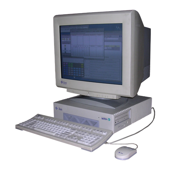
Sun Microsystems Ultra 1 Series Service Manual (218 pages)
Brand:
Sun Microsystems
| Category:
Desktop
| Size: 2.49 MB
Table of Contents
Table of Contents
3
Preface
15
Product Description
23
Ultra 1 Series Overview
23
FIGURE 1-1 Ultra 1 Creator Series Desktop System
24
FIGURE 1-2 Ultra Enterprise 1 Server
24
I/O Devices (Ultra 1 Creator Series Desktop)
25
Supported I/O Devices (Ultra 1 Creator Series Desktop)
26
System Unit Features
26
System Unit Components
27
TABLE 1-2 System Unit/Server Components
27
FIGURE 1-3 System Unit Rear View
29
Sunvts Overview
31
TABLE 2-1 Sunvts Documentation
32
Sunvts Kernel
32
Sunvts User Interface
32
Sunvts Teletype
33
Power-On Self-Test
35
POST Overview
35
Pre-POST Preparation
36
Setting up a Tip Connection
36
TABLE 3-1 Diag-Level Switch Settings
36
Initilizing POST
38
Verifying the Baud Rate
38
Max and Min Levels of POST
39
Diag-Level NVRAM Variable Set to Max
40
Diag-Level NVRAM Variable Set to Min
43
POST Progress and Error Reporting
44
Bypassing POST
45
Typical Error Code Failure Message
45
Additional Keyboard Control Commands
46
FIGURE 3-2 Power LED
46
System and Keyboard Leds
46
System Board Test
47
TABLE 3-2 Keyboard LED Patterns
47
Troubleshooting Procedures
49
Power-On Failure
49
Disk or CD-ROM Drive Failure
50
Video Output Failure
50
TABLE 4-1 Internal Drives Identification
51
Power Supply Test
52
FIGURE 4-1 Power Supply Connector J2601
53
TABLE 4-2 Connector 2601 Pin Description
53
FIGURE 4-2 Power Supply Connector J2603
54
TABLE 4-3 Connector 2603 Pin Description
54
DSIMM Failure
55
TABLE 4-4 DSIMM Physical Memory Address
55
Openboot PROM On-Board Diagnostics
56
Watch-Clock
56
Watch-Net, Watch-Tpe, and Watch-Net-All
57
Probe-Scsi and Probe-Scsi-All
58
Test <Alias Name>, <Device Path>, -All
60
FFB Card
61
TABLE 4-5 Selected OBP On-Board Diagnostic Tests
61
Safety and Tool Requirements
63
Safety Requirements
63
Symbols
63
Modification to Equipment
64
Placement of a Sun Product
64
Safety Precautions
64
Electrostatic Discharge
65
Lithium Battery
65
Power Cord Connection
65
Tools Required
65
FIGURE 6-1 Rear View of the System
67
Power on and off
67
Powering on the System
67
FIGURE 6-2 Sun Type-5 Keyboard
68
Powering off the System
68
Figure
71
FIGURE 7-1 Location of Lock Block
71
Internal Access
71
Removing the Cover
71
Attaching the Wrist Strap
72
FIGURE 7-2 Removing the Cover
72
FIGURE 7-3 Attaching the Wrist Strap
73
Replacing the Cover
73
FIGURE 7-4 Replacing the Cover
74
Major Subassemblies
75
Power Supply
75
Removing the Power Supply
75
FIGURE 8-1 Removing the Power Supply
77
Replacing the Power Supply
77
FIGURE 8-2 Replacing the Power Supply
78
Disk Drive Fan
79
FIGURE 8-3 Securing and Connecting the Power Supply
79
FIGURE 8-4 Fan Power Cable Connection
80
Removing the Disk Drive Fan Assembly
80
FIGURE 8-5 Disk Drive Fan
81
Replacing the Disk Drive Fan
81
FIGURE 8-6 Replacing the Disk Drive Fan
82
Removing the Speaker
83
Speaker
83
FIGURE 8-7 Fan and Speaker Cable Connection
84
FIGURE 8-8 Removing the Fan/Speaker Bracket
85
FIGURE 8-9 Removing the Speaker from the Fan/Speaker Bracket
86
Replacing the Speaker
86
FIGURE 8-10 Replacing the Fan/Speaker Bracket
87
Diskette Cable
88
Removing the Diskette Cable
88
FIGURE 8-11 Removing the Drive Bracket
89
FIGURE 8-12 Diskette Cable
90
Replacing the Diskette Cable
90
FIGURE 8-13 Replacing the Drive Bracket
92
SCSI Cable/Backplane Assembly
92
Removing the SCSI Cable/Backplane Assembly
93
FIGURE 8-14 Scsi/Backplane Assembly Cable Connection
94
FIGURE 8-15 Removing the Backplane Assembly
95
Replacing the SCSI Cable/Backplane Assembly
95
FIGURE 8-16 Replacing the SCSI Backplane
96
Peripheral Power Cable
97
Removing the Peripheral Power Cable
97
FIGURE 8-17 Removing the Drive Bracket
98
FIGURE 8-18 Removing the Peripheral Power Cable Connection
99
TABLE 8-1 Peripheral Power Cable Connections
99
Replacing the Peripheral Power Cable
100
FIGURE 8-20 Replacing the Peripheral Power Cable Connection
101
FIGURE 8-21 Replacing the Drive Bracket
102
Removing the Speaker/Led Cable
103
Speaker/Led Cable
103
FIGURE 8-22 Removing the Drive Bracket
104
FIGURE 8-23 Placing the Bracket on Top of the Disk Drive
105
FIGURE 8-25 Speaker/Led Cable Connection
107
FIGURE 8-26 Speaker Connector on the System Board
107
Replacing the Speaker/Led Cable
108
FIGURE 8-27 Replacing the Drive Bracket
109
Disk Drive
111
Removing a Disk Drive
111
Storage Devices
111
FIGURE 9-1 EMI Door
112
FIGURE 9-2 Removing the Disk Drive
112
Replacing a Disk Drive
113
FIGURE 9-3 Replacing the Disk Drive
114
Media Bay Chassis Bracket
115
Removing the Chassis Bracket
115
FIGURE 9-5 Chassis Bracket
116
FIGURE 9-6 Placing the Chassis Bracket on Top of the Disk Drive
117
Replacing the Chassis Bracket
117
FIGURE 9-7 Connecting Cables to the CD-ROM Drive, 4-MM/8-MM Tape Drive, and Diskette Drive
118
FIGURE 9-8 Positioning the Chassis Bracket
119
CD-ROM Drive or 4-MM/8-MM Tape Drive
120
Removing a CD-ROM Drive or 4-MM/8-MM Tape Drive
120
Replacing a CD-ROM Drive or 4-MM/8-MM Tape Drive
121
Diskette Drive
122
Removing a Diskette Drive
122
FIGURE 9-10 Positioning the Diskette Drive
123
FIGURE 9-11 Positioning the Diskette Drive
123
Replacing a Diskette Drive
124
System Board
127
System Board and Component Replacement
127
Removing a System Board
128
FIGURE 10-1 DC Power Disconnection
129
FIGURE 10-2 Captive Screws on the Back Panel
130
FIGURE 10-3 Sliding the System Board out of the Chassis
130
Replacing a System Board
130
FIGURE 10-4 Removing Sbus Filler Panels from the Back Panel
131
FIGURE 10-5 Card Guide Exploded View
132
FIGURE 10-6 Installing the Card Guide
133
FIGURE 10-7 Sliding the System Board into the Chassis
134
FIGURE 10-8 DC Power Connection
135
TABLE 10-1 Serial Port Jumper Settings
135
FIGURE 10-10 Identifying Jumper Pins
138
Nvram/Tod
138
Removing a NVRAM/TOD
138
Replacing a NVRAM/TOD
139
FIGURE 10-12 Sbus Slot Locations
140
Removing an Sbus Card
140
Sbus Card
140
FIGURE 10-13 Removing an Sbus Card from Slot 0 or
141
Replacing an Sbus Card
142
FIGURE 10-14 Removing the Sbus Card Extractor
143
Removing the Sbus Card Adapter Bracket
143
FIGURE 10-15 Replacing the Sbus Card
144
FFB Card (Workstation Only)
145
Removing an FFB Card
145
Replacing an FFB Card
147
FIGURE 10-19 Seating an FFB Card into the UPA Socket
148
Dsimm
149
FIGURE 10-20 Securing the FFB Card into the Chassis
149
Removing a DSIMM
150
TABLE 10-2 DSIMM Bank and Socket Pair Locations
150
FIGURE 10-21 DSIMM Ejection Lever
151
FIGURE 10-22 Removing a DSIMM
152
Replacing a DSIMM
152
FIGURE 10-23 Installing a DSIMM
154
Removing the System Board Fan
154
System Board Fan
154
FIGURE 10-24 System Board Fan Plastic Cover
155
FIGURE 10-25 System Board Fan
156
Replacing the Board Fan
156
Replacement Parts
159
TABLE 11-1 List of Replacement Parts
159
Product Specifications
161
TABLE A-1 System Unit/Server Physical Specifications
161
Signal Descriptions
165
FIGURE B-1 Keyboard/Mouse Connector Pin Configuration
166
Serial Ports a and B (RS-423/RS-232) Connector
166
TABLE B-1 Keyboard/Mouse Connector Pin Assignments
166
FIGURE B-2 Serial Ports a and B Connector Configuration
167
TABLE B-2 Serial a and B Port Connector Pin Assignments
167
TPE (Twisted Pair Ethernet) Connector
168
Fast Wide SCSI (Small Computer System Interface) Connector
169
FIGURE B-3 TPE Connector Configuration
169
TABLE B-3 TPE Connector Pin Assignments
169
FIGURE B-4 Fast Wide SCSI Connector Configuration
170
TABLE B-4 Fast Wide SCSI Connector Pin Assignments
170
Audio Connectors
173
Parallel Port Connector
174
FIGURE B-6 Parallel Port Connector Pin Configuration
175
Signal Descriptions
175
TABLE B-6 Parallel Port Connector Pin Assignments
175
MII (Media Independent Interface) Connector
176
FIGURE B-7 MII Connector Configuration
177
TABLE B-7 MII Connector Pin Assignments
177
FIGURE B-8 UPA Connector Pin Configuration
179
TABLE B-8 UPA Connector Pin Assignments
179
FIGURE B-9 Graphics Card 13W3 Video con
185
TABLE B-9 Graphics Card 13W3 Video Connector Pin Assignments
185
Functional Description
187
System Unit/Server Overview
187
Functional Description
189
TABLE C-1 Supported Disk Drives
192
Asics
197
Power Supply
201
System Board
201
TABLE C-5 Ultra 1 Creator Series Desktop Workstation and Ultra Enterprise 1 Server Power Supply Budget
202
TABLE C-6 Serial Port Jumper Settings
204
Enclosure
206
Advertisement
Sun Microsystems Ultra 1 Series Service Manual (139 pages)
Brand:
Sun Microsystems
| Category:
Desktop
| Size: 0.48 MB
Table of Contents
Table of Contents
5
Preface
11
1 Product Description
15
System Unit
15
System Illustrations
16
2 Sunvts Overview
19
3 Power-On Self-Test (POST)
21
How to Start POST
21
Max and Min Levels of POST
22
POST Progress and Error Reporting
23
Additional Keyboard Control Commands
23
System and Keyboard Leds
24
Serial Port a POST Output
26
Diag-Level NVRAM Variable Is Set to Max
26
Diag-Level NVRAM Variable Is Set to Min
30
4 Troubleshooting Procedures
31
Power on Fails or no Video
31
Symptom
31
Action
31
Symptom
32
Action
32
Power Supply Test
33
DSIMM Failures
34
Hard Disk or CD-ROM Drive
35
Symptoms
35
Action
36
Symptom
36
Openboot On-Board Diagnostics
37
Watch-Clock
37
Watch-Net, Watch-Aui, Watch-Tpe, Watch-Net-All
37
Test <Alias Name>, Test <Device Path>, Test-All
39
Selected On-Board Diagnostic Tests
39
The Probe-Scsi and Probe-Scsi-All Test
40
System Board Test
41
5 Safety and Tool Requirements
43
Safety Requirements
43
Symbols
43
Safety Precautions
44
Modification to Equipment
44
Placement of a Sun Product
44
Power Cord Connection
44
Electrostatic Discharge
45
Lithium Battery
45
Tools Required
45
6 Power on and off
47
Powering off the System
47
Powering on the System
48
7 Internal Access
49
Removing the Cover
49
Attaching the Wrist Strap
50
Replacing the Cover
51
8 Major Subassemblies
53
Power Supply
54
Removing the Power Supply
54
Replacing the Power Supply
55
Fan Assembly
56
Removing the Fan Assembly
56
Replacing the Fan Assembly
58
Speaker
59
Removing the Speaker
61
Replacing the Speaker
62
Diskette Cable
64
Removing the Diskette Cable
64
Replacing the Diskette Cable
65
SCSI Cable/Backplane
67
Removing the SCSI Cable/Backplane
67
Replacing the SCSI Cable/Backplane
69
Peripheral Power Cable
71
Removing the Peripheral Power Cable
71
Replacing the Peripheral Power Cable
73
Speaker/Led Cable
75
Removing the Speaker/Led Cable
75
Replacing the Speaker/Led Cable
80
9 Storage Devices
83
Disk Drive
83
Removing a Disk Drive
83
Replacing a Disk Drive
85
CD-Rom/Tape Drive
87
Removing the Bracket from the Chassis
87
Removing a CD-Rom/Tape Drive
89
Replacing a CD-Rom/Tape Drive
90
Replacing the Bracket into the Chassis
90
Diskette Drive
93
Removing a Diskette Drive
93
Replacing a Diskette Drive
93
10 System Board and Component Replacement
95
System Board
96
Removing a System Board
96
Replacing a System Board
99
Nvram/Tod
104
Removing a NVRAM/TOD
104
Replacing a NVRAM/TOD
104
Sbus Card
105
Removing an Sbus Card
105
Replacing an Sbus Card
107
Dsimm
111
Removing a DSIMM
112
Replacing a DSIMM
114
System Board Fan
115
Removing the System Board Fan
115
Replacing the System Board Fan
117
11 Replacement Parts
119
List of Replacement Parts
119
Product Specifications
121
Physical Specifications
121
Electrical Specifications
121
Environmental Requirements
122
Signal Descriptions
125
Keyboard/Mouse and Serial Port
125
Keyboard/Mouse
125
Serial Ports a and B (RS-422/RS-232)
126
AUI (Attachment Unit Interface) Connector
127
TPE Connector
128
Scsi
129
Audio Connectors
131
Parallel Port
131
Functional Description
133
System Features
133
Sun Ultra 1 Series System Block Diagram
133
System Board Block Diagram
134
Glossary
137
Index
139
Sun Microsystems Ultra 1 Series Installation Manual (61 pages)
Brand:
Sun Microsystems
| Category:
Desktop
| Size: 1.27 MB
Table of Contents
Table of Contents
3
Opening the System Unit
10
Ouverture de L'unité Système
10
Installing Dsimms
12
Installation des Modules DSIMM
12
Changing the RS-423/232 Jumpers
16
Changement des Cavaliers RS423/232
18
Installing Hard Disk Drives
20
Installation des Unités de Disque Dur
20
Installing the Diskette Drive
24
Installation du Lecteur de Disquette
24
Installing the CD-ROM Drive
30
Installation du Lecteur de CD-ROM
30
Installing Sbus Cards
34
Installation de Cartes Sbus
34
Closing the System Unit
44
Fermeture de L'unité Système
44
Connecting a Twisted-Pair Ethernet Cable
46
Connexion D'un Câble Ethernet à Paire Torsadée
46
Connecting a Thick Ethernet (AUI) Cable
48
Connexion D'un Câble Ethernet Épais (AUI)
48
Installing the Lock Block
50
Installation du Système de Verrouillage
50
Using the CD-ROM Drive
52
Utilisation du Lecteur de CD-ROM
52
What's Next
54
Informations Supplémentaires
54
Safety Agency Compliance
56
Conformité aux Normes de Sécurité
57
Advertisement
Sun Microsystems Ultra 1 Series Reference Manual (40 pages)
Brand:
Sun Microsystems
| Category:
Desktop
| Size: 0.26 MB
Table of Contents
Table of Contents
3
Preface
7
Back Panel Connectors
9
Connector Layout
9
Serial Connectors
10
FIGURE 1-2 DB-25 Serial Connectors
10
Parallel Connector
11
FIGURE 1-3 DB-25 Parallel Connector
11
Keyboard/Mouse Connector
12
FIGURE 1-4 DIN-8 Keyboard/Mouse Connector
12
Media Independent Interface (MII) Connector
13
FIGURE 1-5 40-Pin Miniature-D MII Connector
13
Twisted-Pair Ethernet (TPE) Connector
14
FIGURE 1-6 RJ-45 TPE Connector
14
SCSI Connector
15
FIGURE 1-7 68-Pin SCSI Connector
15
SCSI Implementation
16
SCSI Cabling and Configuration
17
Audio Ports
18
Audio Specifications
19
Graphics Card 13W3 Video Connector
20
FIGURE 1-10 13W3 Video Connector
20
10BASE-T Twisted-Pair Ethernet Link Test
23
Overview
23
FIGURE 2-1 Hosts and Hub in a Local Area Network
24
Technical Discusssion
25
Troubleshooting
26
Moves and Changes
27
Checking or Disabling the Link Test
27
Enabling the Link Test
28
Modem Setup Specifications
29
Setting up the Modem
29
Serial Port Speed Change
30
Recommendations
30
Cable
30
Modem Switch Settings (at Commands)
31
Main Logic Board Jumpers
33
Identifying Jumpers
34
Flash PROM Jumpers
34
FIGURE 4-2 Identifying Jumper Pins
34
Serial Port Jumpers
35
System Specifications
37
Power
37
Environment
37
Physical Specifications
38
Memory Mapping
39
Sun Microsystems Ultra 1 Series Reference Manual (38 pages)
Brand:
Sun Microsystems
| Category:
Desktop
| Size: 0.24 MB
Table of Contents
Table of Contents
3
Preface
7
How this Book Is Organized
7
Related Books
7
Typographic Conventions
8
Back Panel Connectors
9
Connector Layout
9
Serial Connectors
10
FIGURE 1-2 DB-25 Serial Connectors
10
Parallel Connector
11
FIGURE 1-3 DB-25 Parallel Connector
11
Keyboard/Mouse Connector
12
FIGURE 1-4 DIN-8 Keyboard/Mouse Connector
12
Attachment Unit Interface (AUI) Connector
13
FIGURE 1-5 DB-15 AUI Connector
13
Twisted-Pair Ethernet (TPE) Connector
14
SCSI Connector
14
FIGURE 1-6 RJ-45 TPE Connector
14
FIGURE 1-7 50-Pin SCSI Connector
14
SCSI Implementation
15
Audio Ports
16
FIGURE 1-8 Audio Port Locations
16
Audio Specifications
17
Sbus Card 13W3 Video Connector
18
FIGURE 1-9 13W3 Video Connector
18
Twisted-Pair Ethernet Link Test
21
Overview
21
FIGURE 2-1 Hosts and Hub in a Local Area Network
22
Technical Discusssion
24
Troubleshooting
24
Moves and Changes
25
Checking or Disabling the Link Test
25
Enabling the Link Test
26
Modem Setup Specifications
27
Setting up the Modem
27
Serial Port Speed Change
28
Recommendations
29
Cable
29
Modem Switch Settings (at Commands)
29
Main Logic Board Jumpers
31
Identifying Jumpers
32
Flash PROM Jumpers
33
Serial Port Jumpers
34
System Specifications
35
Power
35
Environment
35
Physical Specifications
37
Memory Mapping
37
Sun Microsystems Ultra 1 Series Upgrade Manual (50 pages)
Brand:
Sun Microsystems
| Category:
Desktop
| Size: 0.85 MB
Table of Contents
Table of Contents
5
Preface
7
Upgrade Process
11
Overview
11
Upgrade Kit
12
Tools Required
12
Safety Requirements
13
Symbols
13
Safety Precautions
14
Modification to Equipment
14
Placement of a Sun Product
14
Power Cord Connection
14
Electrostatic Discharge
15
Lithium Battery
15
Electrostatic Discharge (ESD) Precautions
16
System Board and Component Removal
17
Workspace Preparation
18
Removing the Cover
19
Attaching the Wrist Strap
20
Removing a Creator Framebuffer
21
Removing the NVRAM/TOD Module
23
Removing Sbus Cards
24
Removing Dsimms
26
Removing the System Board
28
System Board and Component Replacement
31
Installing the System Board
32
Replacing the NVRAM/TOD Module
39
Replacing Sbus Cards
41
Replacing the Creator Board
43
Replacing Dsimms
45
Installing the Foamblock Spacer
47
Replacing the Cover
48
Resetting #Power-Cycle NVRAM Variable
50
Returning the Old System Board
50
Sun Microsystems Ultra 1 Series Upgrade Manual (34 pages)
To Sun Ultra 30 System
Brand:
Sun Microsystems
| Category:
Desktop
| Size: 0.74 MB
Table of Contents
Upgrade Guide
1
Regulatory Compliance Statements
3
Table of Contents
5
How this Book Is Organized
7
Preface
7
Typographic Conventions
8
Related Documents
9
1 Overview
11
Upgrade Kit
12
Safety Requirements
12
Symbols
13
Safety Precautions
13
Modification to Equipment
13
Placement of a Sun Product
13
Power Cord Connection
13
Electrostatic Discharge
14
Lithium Battery
14
Tools Required
14
Electrostatic Discharge (ESD) Precautions
15
2 Removing Ultra 1 Series Internal Components
17
Powering off the System
17
Removing the Cover
19
Attaching the Wrist Strap
21
Removing Dimms
22
Removing Disk Drives
25
Removing a CD-Rom/Tape Drive
28
Removing the Bracket from the Chassis
28
Removing a CD-ROM or Tape Drive from the Bracket
30
Replacing the Bracket into the Chassis
31
Replacing the Cover
32
Returning the Old System
33
Sun Microsystems Ultra 1 Series Upgrade Manual (28 pages)
Brand:
Sun Microsystems
| Category:
Desktop
| Size: 0.74 MB
Table of Contents
Table of Contents
5
Preface
7
1 Overview
11
Tools Required
11
Upgrade Kit
11
Safety Requirements
12
Symbols
13
System Precautions
14
Lithium Battery
14
2 Performing the Upgrade
15
Overview
15
Powering off the System
16
Removing the Cover
18
Attaching the Antistatic Wrist Strap
20
Removing Dimms
21
Removing a CD-ROM Drive
24
Replacing the Bracket into the Chassis
26
Replacing the Cover
27
Returning the Old System
27
Advertisement
Related Products
Sun Microsystems Ultra 10 EMI
Sun Microsystems Ultra 10
Sun Microsystems Ultra 24
Sun Microsystems Ultra 25
Sun Microsystems Sun Ultra 27
Sun Microsystems Sun Ultra 450
Sun Microsystems Ultra 5
Sun Microsystems Sun Ultra 2 Series
Sun Microsystems Ultra 80
Sun Microsystems Ultra 30
Sun Microsystems Categories
Server
Storage
Desktop
Computer Hardware
Adapter
More Sun Microsystems Manuals
Login
Sign In
OR
Sign in with Facebook
Sign in with Google
Upload manual
Upload from disk
Upload from URL