Sign In
Upload
Manuals
Brands
Sun Microsystems Manuals
Desktop
Ultra 80
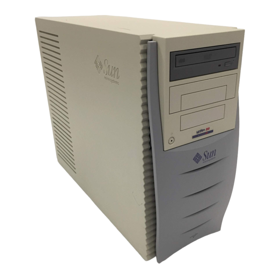
Sun Microsystems Ultra 80 Manuals
Manuals and User Guides for Sun Microsystems Ultra 80. We have
5
Sun Microsystems Ultra 80 manuals available for free PDF download: Service Manual, Upgrade Manual, Installation Manual, Product Note
Sun Microsystems Ultra 80 Service Manual (302 pages)
Brand:
Sun Microsystems
| Category:
Desktop
| Size: 7.3 MB
Table of Contents
Table of Contents
3
Product Description
29
Product Overview
29
I/O Devices
30
FIGURE 1-1 Ultra 80 Workstation
30
System Features
31
FIGURE 1-2 System Front View
33
FIGURE 1-3 System Rear View
34
Replaceable Components
35
TABLE 1-2 Replaceable Components
35
Sunvts Overview
37
Sunvts Description
37
Sunvts Requirements
38
Sunvts References
38
Power-On Self-Test
39
POST Overview
39
How to Use POST
40
Pre-POST Preparation
40
TABLE 3-1 Diag-Level and Diag-Switch? Settings
40
Setting up a Tip Connection
41
FIGURE 3-1 Setting up a Tip Connection
41
Verifying the Baud Rate
42
Initializing POST
43
FIGURE 3-2 Sun Type-6 Keyboard
43
Bypassing POST
44
Maximum and Minimum Levels of POST
44
TABLE 3-2 POST Completion Times
44
Diag-Level Variable Set to Max
45
Diag-Level Variable Set to Min
66
POST Progress and Error Reporting
75
TABLE 3-3 Keyboard LED Patterns
78
Additional Keyboard Control Commands
79
System and Keyboard Leds
79
Initializing Motherboard POST
80
Troubleshooting Procedures
81
Problems During Initial Set-Up
82
Power-On Failure
83
Video Output Failure
84
Hard Drive or CD-ROM Drive Failure
85
TABLE 4-2 Internal Drives Identification
85
Power Supply Troubleshooting
86
FIGURE 4-1 Power Supply Connector Jack Location
87
FIGURE 4-2 Power Supply Connector J4106
88
TABLE 4-3 Power Supply Connector J4106 Pin Description
88
DIMM Failure
89
FIGURE 4-3 Power Supply Connector J4107
89
TABLE 4-4 Power Supply Connector J4107 Pin Description
89
Openboot PROM On-Board Diagnostics
90
Watch-Clock Diagnostic
90
Watch-Net and Watch-Net-All Diagnostics
91
Probe-SCSI and Probe-SCSI-All Diagnostics
92
Test Alias Name, Device Path, -All Diagnostic
93
UPA Graphics Card
94
TABLE 4-6 Selected OBP On-Board Diagnostic Tests
94
Openboot Diagnostics
95
Starting the Openboot Diagnostics Menu
96
Openboot Diagnosticss
98
Pci/Cheerio
99
Ebus DMA/TCR Registers
100
Ethernet
101
TABLE 4-9 Ethernet Diagnostic
101
Keyboard
102
Mouse
102
Floppy
102
Parallel Port
103
TABLE 4-10 Parallel Port Function
103
Serial Port a
104
Serial Port B
105
Nvram
105
Audio
106
Scsi
106
All above
107
How to Get Technical Assistance
109
Sunsolve Online
109
Access1
109
Docs.sun.com
110
Free Services Areas
110
Safety and Tool Requirements
111
Safety Requirements
111
Symbols
112
Safety Precautions
112
Modification to Equipment
112
Placement of a Sun Product
112
Power Cord Connection
113
Electrostatic Discharge
113
Lithium Battery
113
Tools Required
114
Power On/Off and Internal Access
115
Powering off the System/Removing the Access Panel
115
FIGURE 6-1 System Power
116
FIGURE 6-2 Lock Block Location
117
FIGURE 6-3 Removing/Replacing the Access Panel
118
Attaching the Antistatic Wrist Strap
119
Replacing the Access Panel/Powering on the System
120
Figure
120
FIGURE 6-5 Type-6 Keyboard
121
Major Subassemblies
123
Power Supply Assembly
123
Removing the Power Supply Assembly
123
FIGURE 7-1 Removing and Replacing the Power Supply Assembly (Sheet 1 of 2)
125
FIGURE 7-2 Removing and Replacing the Power Supply Assembly (Sheet 2 of 2)
125
Replacing the Power Supply Assembly
126
Power Switch Assembly
127
Removing the Power Switch Assembly
127
Replacing the Power Switch Assembly
128
FIGURE 7-3 Removing and Replacing the Power Switch Assembly
128
DC-To-DC Converter Assembly
129
Removing the DC-To-DC Converter Assembly
129
Replacing the DC-To-DC Converter Assembly
130
FIGURE 7-4 Removing and Replacing the DC-To-DC Converter Assembly
130
Cable Assemblies
131
Removing the Peripheral Power Cable Assembly
131
Replacing the Peripheral Cable Assembly
132
FIGURE 7-5 Removing and Replacing the Peripheral Power Cable Assembly
132
Removing the Diskette Drive Cable Assembly
133
Replacing the Diskette Drive Cable Assembly
134
FIGURE 7-6 Removing and Replacing the Diskette Drive Cable Assembly
134
Removing the Combined Cable Assembly
135
Replacing the Combined Cable Assembly
136
FIGURE 7-7 Removing and Replacing the Combined Cable Assembly
136
Interlock Switch Assembly
137
Removing the Interlock Switch Assembly
137
Replacing the Interlock Switch Assembly
138
FIGURE 7-8 Removing and Replacing the Interlock Switch Assembly
138
Air Guide
139
Removing the Air Guide
139
Replacing the Air Guide
140
FIGURE 7-9 Removing and Replacing the Air Guide
140
Fan Assembly
141
Removing a Fan Assembly
141
Replacing a Fan Assembly
142
FIGURE 7-10 Removing and Replacing a Fan Assembly
142
Speaker Assembly
143
Removing the Speaker Assembly
143
Replacing the Speaker Assembly
144
FIGURE 7-11 Removing and Replacing the Speaker Assembly
144
SCSI Assembly
145
Removing the SCSI Assembly
145
FIGURE 7-12 Removing and Replacing the Hard Drive Cage (Sheet 1 of 2)
147
Replacing the SCSI Assembly
148
FIGURE 7-13 Removing and Replacing the SCSI Assembly (Sheet 2 0F 2)
148
Chassis Foot
149
Removing a Chassis Foot
149
Replacing a Chassis Foot
150
Filler Panels
150
FIGURE 7-14 Removing and Replacing the Chassis Foot
150
Removing a Filler Panel
151
FIGURE 7-15 Removing and Replacing Plastic Filler Panels
151
Replacing a Filler Panel
152
FIGURE 7-16 Removing and Replacing Metal Filler Panels
152
Storage Devices
153
Hard Drive
153
Removing a Hard Drive
153
Replacing a Hard Drive
154
FIGURE 8-1 Removing and Replacing a Hard Drive
154
Peripheral Assembly Drive
155
Removing the Peripheral Assembly
155
FIGURE 8-2 Removing and Replacing the Peripheral Assembly
156
Removing the CD-ROM Drive or any Optional Tape Drive Component
157
Replacing the CD-ROM Drive or any Optional Tape Drive Component
158
Removing the Diskette Drive
158
Replacing the Diskette Drive
159
Replacing the Peripheral Assembly
159
Motherboard and Component Replacement
161
CPU Module
161
Removing a CPU Module
161
Replacing a CPU Module
163
FIGURE 9-1 Removing and Replacing a CPU Module
163
FIGURE 9-2 CPU Placement Diagram
164
TABLE 9-1 CPU Placement Order
164
Nvram/Tod
165
Removing the NVRAM/TOD
165
FIGURE 9-3 Removing and Replacing the NVRAM/TOD
166
Replacing the NVRAM/TOD
167
PCI Card
167
Removing a PCI Card
167
FIGURE 9-4 Removing and Replacing a PCI Card
168
Replacing a PCI Card
169
UPA Graphics Card
169
Removing the UPA Graphics Card
170
Replacing the UPA Graphics Card
171
FIGURE 9-5 Removing and Replacing a UPA Graphics Card
171
Removing the Elite3D UPA Graphics Card
172
FIGURE 9-6 Removing and Replacing the Elite3D UPA Graphics Card
174
Replacing the Elite 3D UPA Graphics Card
175
Elite3D UPA Graphics Card Patch Information
176
Audio Module Assembly
176
Removing the Audio Module Assembly
176
Replacing the Audio Module Assembly
178
FIGURE 9-7 Removing and Replacing the Audio Module Assembly
178
Memory Riser Assembly
179
FIGURE 9-8 Torque-Indicator Driver Storage Location
179
Removing the Memory Riser Assembly
180
FIGURE 9-9 Removing the Memory Riser Assembly (Sheet 1 of 2)
181
Replacing the Memory Riser Assembly
182
FIGURE 9-10 Removing the Memory Riser Assembly (Sheet 2 of 2)
182
FIGURE 9-11 Setting the Memory Riser Assembly Thumbscrew Torque
184
DIMM
185
Removing a DIMM
185
FIGURE 9-12 Removing and Replacing a DIMM (Sheet 1 of 2)
186
Replacing a DIMM
187
FIGURE 9-13 Removing and Replacing a DIMM (Sheet 2 of 2)
187
FIGURE 9-14 DIMM Bank Arrangement
189
Motherboard
190
Removing the Motherboard
191
Replacing the Motherboard
193
FIGURE 9-15 Removing and Replacing the Motherboard
193
FIGURE 9-16 Location of the Motherboard Serial Port Jumpers
194
TABLE 9-3 Serial Port Jumper Settings
194
FIGURE 9-17 Identifying Jumper Pins
195
CPU Shroud Assembly
197
Removing the CPU Shroud Assembly
197
Replacing the CPU Shroud Assembly
198
FIGURE 9-18 Removing and Replacing the CPU Shroud Assembly
198
Illustrated Parts List
199
FIGURE 10-1 System Exploded View
200
TABLE 10-1 Replaceable Components
201
Product Specifications
205
Physical Specifications
206
Electrical Specifications
206
Environmental Requirements
207
Signal Descriptions
209
Power Connectors
209
TABLE B-1 Power Connectors
209
FIGURE B-1 DC-To-DC Converter Connector J4105
210
TABLE B-2 DC-To-DC Converter Connector J4105 Pin Description
210
FIGURE B-2 Power Supply Connector J4106
211
TABLE B-3 Power Supply Connector J4106 Pin Description
211
FIGURE B-3 Power Supply Connector J4107
212
TABLE B-4 Power Supply Connector J4107 Pin Description
212
FIGURE B-4 DC-To-DC Converter Connector J4108
213
FIGURE B-5 PCI Fan Connector J4109
213
TABLE B-5 DC-To-DC Converter Connector J4108 Pin Description
213
TABLE B-6 PCI Fan Connector J4109 Pin Description
213
FIGURE B-6 CPU Fan Connector J4110
214
FIGURE B-7 Combined Cable Assembly Connector J4111
214
TABLE B-7 CPU Fan Connector J4110 Pin Description
214
TABLE B-8 Combined Cable Assembly Connector J4111 Pin Description
214
Serial Ports a and B
215
FIGURE B-8 Peripheral Power Cable Assembly Connector J4112
215
TABLE B-9 Peripheral Power Cable Assembly Connector J4112 Pin Description
215
FIGURE B-9 Serial Port a and B Connector Pin Configuration
216
TABLE B-10 Serial Port a and B Connector Pin Assignments
216
Ultrascsi Connector
217
FIGURE B-10 Ultrascsi Connector Pin Configuration
218
TABLE B-11 Ultrascsi Connector Pin Assignments
218
Parallel Port Connector
221
FIGURE B-11 Parallel Port Connector Pin Configuration
222
TABLE B-12 Parallel Port Connector Pin Assignments
222
Keyboard/Mouse
223
FIGURE B-12 Keyboard/Mouse Connector Pin Configuration
223
TABLE B-13 Keyboard/Mouse Connector Pin Assignments
223
Twisted-Pair Ethernet Connector
224
TPE Cable-Type Connectivity
224
FIGURE B-13 TPE Connector Pin Configuration
224
TABLE B-14 TPE Connector Pin Assignments
224
External UTP-5 Cable Lengths
225
Audio Connectors
225
TABLE B-15 TPE UTP-5 Cables
225
UPA Graphics Card Connectors
226
FIGURE B-14 Audio Connector Configuration
226
FIGURE B-15 UPA Graphics Card Connector Pin Configuration
227
TABLE B-17 UPA Graphics Card Connector Pin Assignments
227
Functional Description
229
System
229
System Overview
230
Upa
231
TABLE C-1 UPA Interconnect
232
TABLE C-2 UPA Port Identification Assignments
232
PCI Bus
233
PCI Cards
234
TABLE C-3 PCI Slot-To-PCI Bus Mapping
234
PCI Slot Logical-To-Physical Mapping
235
Using a Token Ring PCI Card
235
U2P Asic
235
TABLE C-4 PCI Slot Logical-To-Physical Mapping
235
SCSI Controller
236
Pcio Asic
236
Ultrasparc-II Processor
236
Memory System
237
DIMM
240
FIGURE C-5 DIMM Mapping
240
Interleaving
241
TABLE C-5 DIMM Bank-To-U-Number Mapping
241
TABLE C-6 1-Gbyte DIMM Configuration Scenario
242
TABLE C-7 Memory Relative Starting Address with no Interleaving
242
Memory System Timing
243
TABLE C-8 Memory Addressing for 2-Way Interleaving
243
TABLE C-9 Memory Addressing for 4-Way Interleaving
243
Graphics Card Features
244
Graphics Card Performance
245
Peripherals
245
CD-ROM Drive
245
Diskette Drive
246
TABLE C-10 Diskette Drive Signals and Functions
247
Other Peripheral Assembly Options
248
TABLE C-11 18-Gbyte Hard Drive Features
248
Keyboard and Mouse, Diskette, and Parallel Port
249
Keyboard and Mouse Port
249
FIGURE C-6 Keyboard and Mouse, Diskette, and Parallel Port Functional Block Diagram
249
Diskette Port
250
Parallel Port
250
Serial Port
251
Serial Port Components
252
Serial Port Functions
252
EIA Levels
253
Synchronous Rates
253
Asynchronous Rates
253
Slew Rate and Cable Length
253
Ethernet
254
Automatic Negotiation
254
External Cables
255
Audio Card and Connector
255
TABLE C-12 Audio Card Features
255
Scsi
257
Host Adapter
258
Supported Target Devices
259
External Cables
259
Internal SCSI Subassembly
259
TABLE C-13 Supported Target Devices
259
SCSI ID Selection
260
Qsc
261
Pcio
261
U2P
261
Risc
261
Power Supply
263
Control Signals
264
Remote Enable Poweron
264
TABLE C-14 Power Supply Output Values
264
TABLE C-15 Power Supply Control Signal
264
On/Off Functionality
265
System Power Budget
266
TABLE C-16 450-Mhz CPU Module Power Estimate
266
Built-In Speaker
267
Standard System Facilities
267
TABLE C-17 Built-In Speaker Specifications
267
DC-To-DC Converter Assembly
268
Power Management
268
Motherboard
269
Jumper Descriptions
270
Serial Port Jumpers
271
TABLE C-18 Serial Port Jumper Settings
272
Flash PROM Jumpers
273
Enclosure
273
Enclosure Basics
273
Enclosure Features
274
Solaris 2.5.1 and 2.6 Software Upgrades for Systems Faster than 400 Mhz
274
Conformity
275
Declaration of Conformity
275
Regulatory Compliance Statement
276
Agency Compliance
279
German Acoustic Compliance
279
Safety Agency Compliance Statement
281
Advertisement
Sun Microsystems Ultra 80 Upgrade Manual (34 pages)
Brand:
Sun Microsystems
| Category:
Desktop
| Size: 1.68 MB
Table of Contents
Table of Contents
3
Preface
7
1 Safety and Tool Requirements
11
Safety Requirements
11
Symbols
12
Safety Precautions
12
Modification to Equipment
12
Placement of a Sun Product
12
Power Cord Connection
13
Electrostatic Discharge
13
Lithium Battery
13
Tools Required
14
2 Upgrading from an Ultra 2 System
15
Powering off the Ultra 2 System
15
FIGURE 2-1 Rear View of the Ultra 2 System
16
Removing the Ultra 2 System Cover
17
FIGURE 2-2 Sun Type-5 Keyboard
17
FIGURE 2-3 Location of Ultra 2 Lock Block
18
FIGURE 2-4 Removing the Ultra 2 System Cover
18
Attaching the Wrist Strap
19
FIGURE 2-5 Attaching the Wrist Strap to the Ultra 2 Chassis
19
Removing Ultra 2 Dimms
20
FIGURE 2-6 Ultra 2 DIMM Ejection Lever
20
Replacing the Ultra 2 System Cover
21
FIGURE 2-7 Replacing the Ultra 2 System Cover
21
3 Upgrading from an Ultra 30 or an Ultra 60 System
23
Powering off the Ultra 60 System
23
FIGURE 3-1 Ultra 60 System Power-Off (Front Panel)
24
Removing the Ultra 60 Side Access Cover
25
Attaching the Wrist Strap
26
FIGURE 3-3 Removing the Ultra 60 Side Access Cover
26
FIGURE 3-4 Attaching the Wrist Strap to the Ultra 60 Chassis
27
Removing an Elite3D Graphics Card
28
FIGURE 3-5 Removing and Replacing an Elite3D Graphics Card
29
Removing Ultra 60 Dimms
30
FIGURE 3-6 Removing the Ultra 60 Power Supply
31
FIGURE 3-7 Removing a DIMM from an Ultra
32
FIGURE 3-8 Replacing the Ultra 60 Power Supply
33
Replacing the Ultra 60 Side Access Cover
34
FIGURE 3-9 Replacing the Ultra 60 Side Access Cover
34
Sun Microsystems Ultra 80 Installation Manual (32 pages)
Brand:
Sun Microsystems
| Category:
Desktop
| Size: 2.7 MB
Table of Contents
Table of Contents
3
Sun Ultra 30/60/80 Systems Rackmount Installation Guide
5
Preparing the Site
5
Preparing the Rackmounting Tray
7
Preparing the Ultra 30/60 System
14
Installing the Ultra 30/60 System
18
Preparing the Ultra 80 System
24
Installing the Ultra 80 System
28
Advertisement
Sun Microsystems Ultra 80 Installation Manual (22 pages)
Brand:
Sun Microsystems
| Category:
Desktop
| Size: 1.01 MB
Table of Contents
Table of Contents
3
Sun Ultra 80 Rack Mount Installation Guide
5
Preparing Your Site
5
Preparing to Install
7
Preparing the Rack-Mounting Tray
11
Preparing the System
15
Installing the System
17
Sun Microsystems Ultra 80 Product Note (12 pages)
Brand:
Sun Microsystems
| Category:
Desktop
| Size: 0.24 MB
Advertisement
Related Products
Sun Microsystems Ultra 40
Sun Microsystems Ultra 24
Sun Microsystems Ultra 25
Sun Microsystems Sun Ultra 27
Sun Microsystems Ultra 30
Sun Microsystems Ultra 45
Sun Microsystems Sun Ultra 60
Sun Microsystems Sun Ultra 450
Sun Microsystems Ultra 1 Series
Sun Microsystems Ultra 10 EMI
Sun Microsystems Categories
Server
Storage
Desktop
Computer Hardware
Adapter
More Sun Microsystems Manuals
Login
Sign In
OR
Sign in with Facebook
Sign in with Google
Upload manual
Upload from disk
Upload from URL