Sun Microsystems Ultra 1 Series Service Manual
Hide thumbs
Also See for Ultra 1 Series:
- Service manual (218 pages) ,
- Installation manual (61 pages) ,
- Upgrade manual (50 pages)

Related Manuals for Sun Microsystems Ultra 1 Series


Summary of Contents for Sun Microsystems Ultra 1 Series
- Page 1 Sun Ultra 1 Series Service Manual A Sun Microsystems, Inc. Business 901 San Antonio Road Palo Alto, , CA 94303-4900 Part No: 802-3819-10 Revision A, November 1995...
- Page 2 USA 650 960-1300 fax 650 969-9131...
- Page 3 Sun Ultra 1 Series Service Manual Part No: 802-3819-10 Revision A, November 1995...
- Page 4 52.227-14(g)(2)(6/87) and FAR 52.227-19(6/87), or DFAR 252.227-7015(b)(6/95) and DFAR 227.7202-3(a). Sun, Sun Microsystems, the Sun logo, and Solaris are trademarks or registered trademarks of Sun Microsystems, Inc. in the United States and in other countries. All SPARC trademarks are used under license and are trademarks or registered trademarks of SPARC International, Inc.
-
Page 5: Table Of Contents
Contents Preface x Product Description 1 System Unit 1 System Illustrations 2 SunVTS Overview 5 Power-On Self-Test (POST) 7 How to Start POST 7 Max and Min Levels of POST 8 POST Progress and Error Reporting 9 Additional Keyboard Control Commands 9 System and Keyboard LEDs 10 Serial Port A POST Output 12 Diag-level NVRAM Variable is Set to Max 12... - Page 6 Safety Precautions 30 Modification to Equipment 30 Placement of a Sun Product 30 Power Cord Connection 30 Electrostatic Discharge 31 Lithium Battery 31 Tools Required 31 Power On and Off 33 Sun Ultra 1 Series Service Manual ♦ Revision A, November 1995...
- Page 7 Powering Off the System 33 Powering On the System 34 Internal Access 35 Removing the Cover 35 Attaching the Wrist Strap 36 Replacing the Cover 37 Major Subassemblies 39 Power Supply 40 Removing the Power Supply 40 Replacing the Power Supply 41 Fan Assembly 42 Removing the Fan Assembly 42 Replacing the Fan Assembly 44...
- Page 8 Replacing an SBus Card 93 DSIMM 97 Removing a DSIMM 98 Replacing a DSIMM 100 System Board Fan 101 Removing the System Board Fan 101 Replacing the System Board Fan 103 Sun Ultra 1 Series Service Manual ♦ Revision A, November 1995...
- Page 9 AUI (Attachment Unit Interface) Connector 113 TPE Connector 114 SCSI 115 Audio Connectors 117 Parallel Port 117 Functional Description 119 System Features 119 Sun Ultra 1 Series System Block Diagram 119 System Board Block Diagram 120 Glossary 123 Index 125 viii Contents...
- Page 10 Sun Ultra 1 Series Service Manual ♦ Revision A, November 1995...
-
Page 11: Preface
Preface The Sun Ultra 1 Series Service Manual tells how to remove and replace system parts. This document applies to both Sun Ultra 1 Model 140 and Sun Ultra 1 Model 170. Chapter 11 lists the replacement parts. This document also tells how to... - Page 12 Book titles, new words or terms, or Read Chapter 6 in the User’s Guide. AaBbCc123 words to be emphasized These are called class options. You must be root to do this. Sun Ultra 1 Series Service Manual ♦ Revision A, November 1995...
- Page 13 Procedures contained in this document must be performed by qualified service-trained maintenance providers. Only people who have been trained by the ® Sun Microsystems training facilities (or by Sun Microsystems affiliates) and have been certified as required by local and national laws are considered qualified.
- Page 14 Ordering Sun Documents The SunDocs Order Desk is a distribution center for Sun Microsystems technical documentation. It accepts all major credit cards and company purchase orders. You can order documentation in the following ways: Ordering Documentation TABLE P–4...
-
Page 15: Product Description
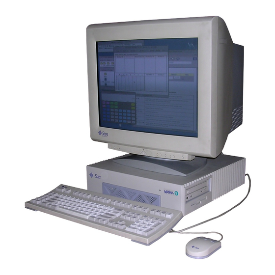
CHAPTER Product Description System Unit The major components of the Sun Ultra 1 Series workstation are: 4 CPU system 4 Monitor 4 Sun Type-5c keyboard 4 Compact 1 mechanical mouse The following figures illustrate the CPU system: 4 Figure 1–1 shows the front view of the system. -
Page 16: System Illustrations
System Illustrations Figure 1–1 Front View of the System Figure 1–2 Rear View of the System Sun Ultra 1 Series Service Manual ♦ Revision A, November 1995... - Page 17 Figure 1–3 Top View of the System with the Cover Removed Product Description...
- Page 18 Sun Ultra 1 Series Service Manual ♦ Revision A, November 1995...
-
Page 19: Sunvts Overview
CHAPTER SunVTS Overview You can use SunVTS, the Sun Validation and Test Suite, to run individual tests for verifying the configuration and functionality of most hardware controllers and devices. These are the main features of the SunVTS environment: 4 SunVTS kernel (vtsk) The SunVTS kernel controls all aspects of the testing. - Page 20 Each test description describes the various test options and gives command line arguments. 4 SunVTS Quick Reference Card (802-3622) This card gives an overview of the main features of the SunVTS OPEN LOOK interface. Sun Ultra 1 Series Service Manual ♦ Revision A, November 1995...
-
Page 21: Power-On Self-Test (Post)
CHAPTER Power-On Self-Test (POST) The Power On Self Test (POST) diagnostics reside in the system"s OpenBoot PROM located on the system board. These diagnostics are useful in determining if a portion of the system has failed and should be replaced. Under normal operating conditions, POST does not run automatically when the system is powered on. -
Page 22: Max And Min Levels Of Post
To observe POST messages on serial port A, you must connect a terminal to port A or set up a tip connection to another workstation. For information about setting up tip connections, refer to the Solaris software reference manuals. Sun Ultra 1 Series Service Manual ♦ Revision A, November 1995... -
Page 23: Post Progress And Error Reporting
POST Progress and Error Reporting While POST is running, observe the Caps Lock key on the system keyboard. It should flash on and off to indicate that tests are running. Additional POST progress indication is visible when a terminal or tip line is connected to serial port A. If an error occurs during POST, the Caps Lock key will stop flashing and an error code will be displayed using the lights on the keyboard"s Caps Lock, Compose, Scroll Lock, and Num Lock keys. -
Page 24: System And Keyboard Leds
Figure 3–2 shows the location of the LED keys on the Sun type 5-c keyboard. Table 3–1 lists the meaning of the LED keys. Figure 3–2 Arrangement of the Sun Type 5-c Keyboard LEDs Sun Ultra 1 Series Service Manual ♦ Revision A, November 1995... - Page 25 The Keyboard LED Patterns TABLE 3–1 Scroll Meaning of LED Caps Lock Compose Lock Num Lock Bit Value Pattern Blink x000 POST in progress 0000 POST successful completion 0001 DSIMM in slot U 0601 fail 0010 DSIMM in slot U 0701 fail 0011 DSIMM in slot U 0602...
-
Page 26: Serial Port A Post Output
>PROM Datapath Test PASSED >FPU Register Test > FSR Read/Write Test >FSR Read/Write Test PASSED >NVRAM Test >MMU Enable Test > DMMU Registers Access Test >DMMU Registers Access Test PASSED Sun Ultra 1 Series Service Manual ♦ Revision A, November 1995... - Page 27 > DMMU TLB DATA RAM Access Test >DMMU TLB DATA RAM Access Test PASSED > DMMU TLB TAGS Access Test >DMMU TLB TAGS Access Test PASSED > IMMU Registers Access Test >IMMU Registers Access Test PASSED > IMMU TLB DATA RAM Access Test >IMMU TLB DATA RAM Access Test PASSED >...
- Page 28 I/D MMU TLB Load and Initialize Test >I/D MMU TLB Load and Initialize Test PASSED > Access Priviledged Data Page Test >Access Priviledged Data Page Test PASSED > Write to Protected Data Page Test Sun Ultra 1 Series Service Manual ♦ Revision A, November 1995...
- Page 29 >Write to Protected Data Page Test PASSED > Read/Write to Invalid Data Page Test >Read/Write to Invalid Data Page Test PASSED > Execute from Invalid Instr. Page Test >Execute from Invalid Instr. Page Test PASSED >Graphic Instructions Test >Data Cache Test >...
-
Page 30: Diag-Level Nvram Variable Is Set To Min
32 + 32 : 64 Megabytes Probing Memory Bank #3 0 Megabytes Probing /sbus@1f,0 at 0,0 Nothing there Probing /sbus@1f,0 at 1,0 Nothing there Probing /sbus@1f,0 at 2,0 cgsix Sun Ultra 1 Series Service Manual ♦ Revision A, November 1995... -
Page 31: Troubleshooting Procedures
CHAPTER Troubleshooting Procedures This chapter describes how to troubleshoot possible problems and includes the corrective actions you can take. 4 “Power On Fails or No Video” on page 17“Power On Fails or No Video” on page 4 “Power Supply Test” on page 19“Power Supply Test” on page 19 4 “DSIMM Failures”... -
Page 32: Symptom
If the AC connection to the monitor is correct and the video cable is correctly connected, the system monitor or the system"s internal graphics card may be defective. Replace the monitor or the graphics card. Sun Ultra 1 Series Service Manual ♦ Revision A, November 1995... -
Page 33: Power Supply Test
Power Supply Test Use a VOM (volt-ohm-milliammeter) to check the power supply output voltages. The power supply connectors J2601 and J2603 must remain connected to the system board. Place the VOM negative probe on one of the Gnd (ground) pins in the connector, and test the +12v, -12v, +5v, +3.3v and +3.0v power pins individually with the VOM positive probe. -
Page 34: Dsimm Failures
DSIMM location (U number) as part of the memory error message. If you encounter this situation, and the only available information is a physical memory address and failing byte (or bit), use the following table to locate the defective DSIMM. Sun Ultra 1 Series Service Manual ♦ Revision A, November 1995... -
Page 35: Hard Disk Or Cd-Rom Drive
DSIMM Physical Memory Address TABLE 4–3 Physical Physical Memory Memory DSIMM Slot Location Address Start Address End Bank 0 0000 0000 0fff ffff U0701 (byte 00-15, bits 000-127) U0601 (byte 16-31, bits 128-255) Bank 1 1000 000 1fff ffff U0702 (byte 00-15, bits 000-127) U0602 (byte 16-31, bits 128-255) Bank 2 2000 000... -
Page 36: Action
TOSHIBA XM-5301TASUN4XCD173506/22/95 If the drives respond and a message is displayed, the system"s SCSI controller has successfully probed the devices. This is an indication that the system"s main logic Sun Ultra 1 Series Service Manual ♦ Revision A, November 1995... -
Page 37: Openboot On-Board Diagnostics
board is working correctly. If one drive does not respond to the probe but the others do, replace the unresponsive drive. If your system has only one internal disk drive and the probe-scsi test fails to show the device in the message, replace the drive. If after replacing the drive the problem still persist, replace the main logic board. - Page 38 The Sun Ultra 1 Series has two types of on-board Ethernet interfaces: 10 BASE-T (also called twisted-pair Ethernet or TPE) and 10 BASE5 (also called thick ethernet or AUI). Only one Ethernet cable is connected to the back of the system. The system automatically selects which interface is connected and active.
-
Page 39: Test
Testing floppy disk system. A formatted disk should be in the drive. Test succeeded. Selected On-Board Diagnostic Tests The on-board diagnostic tests that you can run on the Sun Ultra 1 Series systems are listed in Table 4–5. Selected On-Board Diagnostics Tests TABLE 4–5..., Test , Test-All -
Page 40: The Probe-Scsi And Probe-Scsi-All Test
The probe-scsi test sends an inquiry command to internal and external SCSI devices connected to the Sun Ultra 1 Series on-board SCSI interface. If a SCSI device is connected and powered up the target address, unit number, device type, and manufacturer"s name is displayed. -
Page 41: System Board Test
Unit 0 Disk SEAGATE ST31200W SUN1.058724 Target 6 Unit 0 Removable Read Only device TOSHIBA XM-5301TASUN4XCD1735 The probe-scsi-all test sends an inquiry command to all SCSI devices on all the SCSI host adapters installed in the system. The first identifier listed in the display is the SCSI host adapter"s address in the system"s device tree, followed by the SCSI device identification data. - Page 42 To receive additional POST failure information, you may connect a terminal to serial port A on the system. With the terminal connected, failure messages that give more information about the failure may appear. Sun Ultra 1 Series Service Manual ♦ Revision A, November 1995...
-
Page 43: Safety And Tool Requirements
CHAPTER Safety and Tool Requirements Before servicing any part of the Sun Ultra 1 Series system, read the instructions and cautions in this section. This information explains how to work safely when servicing a Sun Microsystems product. Safety Requirements For your protection, observe the following safety precautions when setting up your equipment: 4 Follow all cautions, warnings, and instructions marked on the equipment. -
Page 44: Safety Precautions
Caution - Not all power cords have the same current ratings. Household extension cords do not have overload protection. Do not use household extension cords with your Sun product. Sun Ultra 1 Series Service Manual ♦ Revision A, November 1995... -
Page 45: Electrostatic Discharge
Caution - The power switch of this product functions as a standby type device only. The power cord serves as the primary disconnect device for the system. Be sure to plug the power cord into a grounded power outlet that is nearby the system and is readily accessible. - Page 46 Sun Ultra 1 Series Service Manual ♦ Revision A, November 1995...
-
Page 47: Power On And Off
CHAPTER Power On and Off 4 “Powering Off the System” on page 33“Powering Off the System” on page 33 4 “Powering On the System” on page 34“Powering On the System” on page 34 Powering Off the System Before turning off system power, shut down the operating system. Failure to shut down the operating system can result in loss of data. -
Page 48: Powering On The System
Turn the power on to the attached peripherals first so the system will recognize the peripherals when the system is powered on. 2. Turn on the power switch to the monitor. 3. Turn on the power switch to the system. Sun Ultra 1 Series Service Manual ♦ Revision A, November 1995... -
Page 49: Internal Access
CHAPTER Internal Access 4 “Removing the Cover” on page 35“Removing the Cover” on page 35 4 “Attaching the Wrist Strap” on page 36“Attaching the Wrist Strap” on page 36 4 “Replacing the Cover” on page 37“Replacing the Cover” on page 37 Removing the Cover 1. -
Page 50: Attaching The Wrist Strap
2. Peel the liner from the copper foil at the opposite end of the wrist strap and attach the copper end of the wrist strap to the top of the power supply. Sun Ultra 1 Series Service Manual ♦ Revision A, November 1995... -
Page 51: Replacing The Cover
Figure 7–3 Attaching the Wrist Strap Replacing the Cover 1. Position the cover on the system as shown. See Figure 7–4. Internal Access... - Page 52 firmly seated. See Figure 7–4. 3. Tighten the captive screws on the back panel. 4. Replace the lock block with a Phillips screwdriver. See Figure 7–1. Sun Ultra 1 Series Service Manual ♦ Revision A, November 1995...
-
Page 53: Major Subassemblies
4 “Powering On the System” on page 34“Powering On the System” on page 34 The following is the list of the major subassemblies for the Sun Ultra 1 Series system: 4 “Power Supply” on page 40“Power Supply” on page 40 4 “Fan Assembly”... -
Page 54: Power Supply
4. Remove the DC harness from the clip and disconnect the DC connector from the peripheral power cable at P1. Figure 8–1 Removing the Power Supply 5. Loosen the power supply captive screw on the back panel. Sun Ultra 1 Series Service Manual ♦ Revision A, November 1995... -
Page 55: Replacing The Power Supply
See Figure 8–1. 6. Push the power supply toward the front side of the chassis to disengage the mounting hooks. 7. Tilt the power supply slightly toward the system board, and lift it out of the chassis. 1. Lower the power supply into the chassis and push it all the way toward the back panel. -
Page 56: Fan Assembly
6. Connect the DC connector on the system board at J2601. Figure 8–3 Securing and Connecting the Power Supply Fan Assembly 1. Disconnect the fan power cable from the fan. See Figure 8–4. Sun Ultra 1 Series Service Manual ♦ Revision A, November 1995... - Page 57 Figure 8–4 Fan and Power Cable Connection 2. Press the middle tab on the fan/speaker bracket toward the center of the chassis. See Figure 8–5. 3. Grasp the fan and pull it from the fan/speaker bracket in the chassis. Major Subassemblies...
-
Page 58: Replacing The Fan Assembly
1. Position the fan assembly so the arrow on the fan faces the chassis, and the harness faces the power supply. See Figure 8–6.The arrow on the fan indicates the airflow direction. 2. Insert the fan assembly into the fan/speaker bracket in the chassis. Sun Ultra 1 Series Service Manual ♦ Revision A, November 1995... -
Page 59: Speaker
Figure 8–6 Replacing the Fan Assembly 3. Connect the fan connector to the fan power cable. See Figure 8–4. Speaker 1. Disconnect the fan power cable from the fan. See Figure 8–7. 2. Use a long-nose plier to disconnect the speaker connectors. Major Subassemblies... - Page 60 Fan and Speaker Cable Connection 3. Push in the tabs of the fan/speaker bracket on the chassis. See Figure 8–8. 4. Grasp and remove the fan/speaker bracket from the chassis. Sun Ultra 1 Series Service Manual ♦ Revision A, November 1995...
-
Page 61: Removing The Speaker
Figure 8–8 Removing the Fan/Speaker Bracket from the Chassis 5. Release the bottom part of the speaker from the fan/speaker bracket, and remove the speaker. See Figure 8–9. Major Subassemblies... -
Page 62: Replacing The Speaker
Make sure the speaker connectors are on the top. See Figure 8–10. 2. Insert the fan/speaker bracket into the chassis. Make sure the tabs are lock into the chassis to ensure proper replacement. Sun Ultra 1 Series Service Manual ♦ Revision A, November 1995... - Page 63 Figure 8–10 Replacing the Fan/Speaker Bracket into the Chassis 1. Connect the speaker cable to the speaker connectors with a long-nose plier. See Figure 8–7. The speaker cable has two different connector sizes. These connectors are keyed, to allow the correct connection to the speaker. 2.
-
Page 64: Diskette Cable
2. Remove the DC harness from the clip located on the drive bracket. See Figure 8–11. 3. Push the drive bracket toward the disk drive bay, and gently flip it over. Place it on top of the disk drive bay. Sun Ultra 1 Series Service Manual ♦ Revision A, November 1995... -
Page 65: Replacing The Diskette Cable
See Figure 8–12. Figure 8–12 Diskette Cable 4. Disconnect the diskette cable from the diskette drive. See Figure 8–12. 5. Disconnect the diskette cable from the SCSI backplane. 1. Connect the replacement diskette cable to the diskette drive. See Figure 8–12. Major Subassemblies... - Page 66 The hooks in the base of the chassis must lock into the holes in the bottom of the drive bracket. See Figure 8–13. Figure 8–13 Replacing the Drive Bracket Sun Ultra 1 Series Service Manual ♦ Revision A, November 1995...
-
Page 67: Scsi Cable/Backplane
4. Route the DC harness through the clip on the side of the bracket. See Figure 8–13. 5. Replace the two drive bracket mounting screws on the chassis. SCSI Cable/Backplane 1. Remove the drive bracket from the chassis. See “Removing the Bracket from the Chassis” on page 73.” 2. - Page 68 See Figure 8–14. 7. Pull the SCSI cable out through the disk drive bay. 8. Remove the SCSI cable from the three cable clips in the base of the chassis. Sun Ultra 1 Series Service Manual ♦ Revision A, November 1995...
-
Page 69: Replacing The Scsi Cable/Backplane
Figure 8–15 Removing the SCSI Backplane 9. Remove the SCSI backplane from the bracket. See Figure 8–15. 1. Route the SCSI cable under the three cable clips in the base of the chassis and through the opening near the front edge of the system board. See Figure 8–16. - Page 70 file systems may fail to mount. 8. Replace the bracket into the chassis. See “Replacing the Bracket into the Chassis” on page 76.” Sun Ultra 1 Series Service Manual ♦ Revision A, November 1995...
-
Page 71: Peripheral Power Cable
Peripheral Power Cable 1. Remove the two screws securing the drive bracket to the chassis. See Figure 8–17. Figure 8–17 Removing the Drive Bracket 2. Remove the DC harness from the clip located on the drive bracket. See Figure 8–17. 3. - Page 72 5. Detach the peripheral power cable from the peripherals and the fan. See Table 8–1 and Figure 8–18. Peripheral Power Cable Connection TABLE 8–1 Connector Peripheral Diskette drive CD-ROM/tape drive Sun Ultra 1 Series Service Manual ♦ Revision A, November 1995...
-
Page 73: Replacing The Peripheral Power Cable
Peripheral Power Cable Connection TABLE 8–1 (continued) Connector Peripheral SCSI backplane (PWR) Fan power connector 6. Remove the peripheral power cable from the cable clips on the SCSI backplane. Figure 8–19 Peripheral Power Cable Routing on the SCSI Backplane 1. Connect the replacement peripheral power cable to each applicable part. See Table 8–1 and Figure 8–20. - Page 74 4. Connect the DC harness to the peripheral power cable at P1. 5. Reroute the DC harness through the clip on the bracket. 6. Replace the two screws to secure the drive bracket to the chassis. Sun Ultra 1 Series Service Manual ♦ Revision A, November 1995...
-
Page 75: Speaker/Led Cable
Figure 8–21 Replacing the Drive Bracket Speaker/LED Cable Note - If the system does not contain a CD-ROM or a tape drive, go to Step 5. 1. Remove the two screws securing the drive bracket to the chassis. Major Subassemblies... - Page 76 See Figure 8–22. 3. Push the CD-ROM/tape drive bracket toward the disk drive bay, and gently flip it over. Place it on top of the disk drive bay. See Figure 8–23. Sun Ultra 1 Series Service Manual ♦ Revision A, November 1995...
- Page 77 Figure 8–23 Placing the Bracket on Top of the Disk Drive 4. Slide the LED from the cavity, and remove the speaker/LED cable from the two cable clips. See Figure 8–24. Major Subassemblies...
- Page 78 Figure 8–24 Removing/Replacing the Speaker /LED Cable from the Chassis 5. Disconnect the cable from the speaker with a long-nose plier. See Figure 8–25. Sun Ultra 1 Series Service Manual ♦ Revision A, November 1995...
- Page 79 Figure 8–25 Speaker Cable Connection 6. Remove any SBus card(s) located in slot 0 and/or 1. See “Removing an SBus Card ” on page 91.“ 7. Disconnect the speaker/LED cable from the system board at J2001. See Figure 8–26. 8. Pull the speaker/LED cable from the chassis, removing it from the securing clips on the SCSI backplane.
-
Page 80: Replacing The Speaker/Led Cable
4. Route the speaker/LED cable through the two cable clips, and insert the LED into the cavity. If you are replacing the LED itself, make sure the flat side of the LED is lined up with the black wire. Sun Ultra 1 Series Service Manual ♦ Revision A, November 1995... - Page 81 Note - If the system contains a CD-ROM or a tape drive, go to Steps 5 through 8. Otherwise, you are done replacing the fan/speaker cable. 5. Position the bracket assembly into the chassis, and slide it toward the opening in the side of the chassis.
- Page 82 Figure 8–27 Replacing the Bracket to the Chassis Sun Ultra 1 Series Service Manual ♦ Revision A, November 1995...
-
Page 83: Storage Devices
CHAPTER Storage Devices This chapter describes how to remove and replace the storage device units. Refer to the following before you remove any part: 4 “Powering Off the System” on page 33“Powering Off the System” on page 33 4 “Removing the Cover” on page 35“Removing the Cover” on page 35 4 “Attaching the Wrist Strap”... - Page 84 1. 3. Unlatch the drive handle and swing it open. See Figure 9–2. The connector on the back of the drive will be disconnected once the drive is ejected. Sun Ultra 1 Series Service Manual ♦ Revision A, November 1995...
-
Page 85: Replacing A Disk Drive
Figure 9–2 Removing the Disk Drive 4. Hold the drive handle and pull it out to remove the drive from the chassis. See Figure 9–2. 5. Place the drive on an antistatic surface. Note - If there are two drives, install the drives into their original slots. If the drives are not installed in their original slots, the system may fail to boot, or file systems may fail to mount. - Page 86 Position the EMI door on the chassis. The two tabs should be hooked into the two slots. See Figure 9–4. b. Push the door in until it is flush with the chassis. Sun Ultra 1 Series Service Manual ♦ Revision A, November 1995...
-
Page 87: Cd-Rom/Tape Drive
Figure 9–4 Replacing the EMI Door CD-ROM/Tape Drive 1. Remove the two screws from the chassis that secure the drive bracket. See Figure 9–5. Storage Devices... - Page 88 3. Disconnect the DC harness from the peripheral power cable at P1. 4. Push the drive bracket toward the disk drive bay, and gently flip it over. Place it on top of the disk drive bay. See Figure 9–6. Sun Ultra 1 Series Service Manual ♦ Revision A, November 1995...
-
Page 89: Removing A Cd-Rom/Tape Drive
Figure 9–6 Placing the Drive Bracket on Top of the Disk Drive 5. Disconnect the SCSI cable from the CD-ROM/tape drive. See Figure 9–6. 6. Disconnect the peripheral power cable from the CD-ROM/tape drive (P3), and from the diskette drive (P2) if any. 7. -
Page 90: Replacing A Cd-Rom/Tape Drive
3. Replace the four screws to secure the CD-ROM/tape drive to the bracket. 1. Place the drive bracket on top of the disk drive bay. See Figure 9–8. 2. Connect the SCSI cable to the CD-ROM/tape drive (if present). Sun Ultra 1 Series Service Manual ♦ Revision A, November 1995... - Page 91 Figure 9–8 Connecting the Cables from the CD-ROM/Tape and Diskette Drive 3. Connect the diskette cable to the diskette drive (if any). See Figure 9–8. 4. Connect the peripheral power cable to the CD-ROM/tape drive (P3), and to the diskette drive (P2) if any. 5.
- Page 92 6. Connect the DC harness to the peripheral power cable at P1. See Figure 9–9. 7. Route the DC harness through the clip on the bracket. 8. Tighten the two screws on the chassis. Sun Ultra 1 Series Service Manual ♦ Revision A, November 1995...
-
Page 93: Diskette Drive
Diskette Drive 1. Remove the bracket from the chassis. See “Removing the Bracket from the Chassis” on page 73 and “Removing a CD-ROM/Tape Drive” on page 75. 2. Position the drive bracket on top of a flat surface as shown. See Figure 9–10. - Page 94 Positioning the Diskette Drive 3. Replace the bracket into the chassis. See “Replacing a CD-ROM/Tape Drive” on page 76 if applicable, and “Replacing the Bracket into the Chassis” on page 76. Sun Ultra 1 Series Service Manual ♦ Revision A, November 1995...
-
Page 95: System Board And Component Replacement
4 “Replacing the Cover” on page 37“Replacing the Cover” on page 37 4 “Powering On the System” on page 34“Powering On the System” on page 34 The following is the list of all replacement parts related to the Sun Ultra 1 Series system board: 4 “System Board”... -
Page 96: System Board
See “Removing an SBus Card ” on page 91. 3. Remove all DSIMMs from the system board. See “DSIMM” on page 97. 4. Disconnect the SCSI cable from the system board at J2602. See Figure 10–1. Sun Ultra 1 Series Service Manual ♦ Revision A, November 1995... - Page 97 Figure 10–1 Disconnecting Connectors from the System Board 5. Disconnect the DC power cables from the system board at J2601 and J2603. See Figure 10–1. 6. Disconnect the speaker/LED cable from the system board at J2001. See Figure 10–2. System Board and Component Replacement...
- Page 98 7. Loosen both captive screws on the back panel. See Figure 10–3. Figure 10–3 Captive Screws on the Back Panel 8. Grasp the system board and slide it out of the chassis. Sun Ultra 1 Series Service Manual ♦ Revision A, November 1995...
-
Page 99: Replacing A System Board
Figure 10–4 Sliding the System Board Out of the Chassis 9. Place the system board on an antistatic surface. Handle the system board by the back panel or by the edges only. 1. Remove SBus filler panel(s) from the replacement board so the rear panel of the replacement board and the defective board look the same. - Page 100 2. Slide the board into the rear of the chassis. Both sides of the board must fit into the slots in the plastic board guides in the base of the chassis. See Figure 10–6. Sun Ultra 1 Series Service Manual ♦ Revision A, November 1995...
- Page 101 Figure 10–6 Sliding the System Board Into The Chassis 3. Tighten the two captive screws on the back panel. See Figure 10–3. 4. Connect the speaker/LED cable to the system board at J2001. See Figure 10–2. 5. Connect the DC power cables to the system board at J2601 and J2603. See Figure 10–1.
- Page 102 J2104 and J2105. Jumper pins are located immediately adjacent to the part number. Pin 1 is marked with an asterisk in any of the positions shown. See Figure 10–8. Sun Ultra 1 Series Service Manual ♦ Revision A, November 1995...
- Page 103 Figure 10–8 Identifying Jumper Pins Be sure the serial port jumpers are set correctly. Use a pair of long-nose pliers to move both jumpers to the correct positions. Table 10–1 shows the correct setting for the serial port jumpers. Serial Port Jumper Settings TABLE 10–1 Default Shunt on Jumper...
-
Page 104: Nvram/Tod
Gently wiggle the NVRAM/TOD as necessary. 3. Place the NVRAM/TOD with its carrier on an antistatic surface. 1. Position the replacement NVRAM/TOD on the system board. See Figure 10–9. Sun Ultra 1 Series Service Manual ♦ Revision A, November 1995... -
Page 105: Sbus Card
The carrier is keyed so the NVRAM/TOD can be installed only one way. 3. Push the NVRAM/TOD into the carrier until it sits tightly in the socket. SBus Card Sun Ultra 1 Series has three SBus slots. See Figure 10–10 for the location of each SBus slot. Figure 10–10... - Page 106 4 If the SBus card is located in SBus slot 2, pull the card retainer up. See Figure 10–12. There is only one card retainer for the SBus slot 2. Figure 10–11 Removing an SBus Card from Slot 0 or 1 Sun Ultra 1 Series Service Manual ♦ Revision A, November 1995...
-
Page 107: Replacing An Sbus Card
Figure 10–12 Removing an SBus Card from Slot 2 2. Grasp the SBus card at both corners, and pull it up to disconnect it from the socket. Caution - Avoid applying force to one end or one side of the board. It damages the connector pins. - Page 108 4. Slide the card at an angle into the system unit by hooking the card backplate under the two tabs on the back panel. See Figure 10–14. Be sure the card backplate shows through the slot on the back panel. Sun Ultra 1 Series Service Manual ♦ Revision A, November 1995...
- Page 109 Figure 10–14 Replacing the SBus Card 5. Align the connector with the SBus socket. Gently press the corners of the card to push the connector into the socket. Do not force the card, or you may damage the pins on the card. If the SBus card is located in SBus slot 0 or 1, see Figure 10–15.
- Page 110 Figure 10–15 Lock in the SBus Card Retainers, SBus Slots 0 or 1 Sun Ultra 1 Series Service Manual ♦ Revision A, November 1995...
-
Page 111: Dsimm
Figure 10–16 Lock in the SBus Card Retainer, SBus Slot 2 DSIMM Caution - DSIMMs are made of electronic components that are extremely sensitive to static electricity. Ordinary mounts of static from your clothes or work environment can destroy the modules. Do not remove any DSIMM from the anti-static container until you are ready to install it on the system board. -
Page 112: Removing A Dsimm
It should also be inserted into the same socket as the defective one. The Sun Ultra 1 Series system must have a pair of DSIMMs in bank 0 to be able to boot. Up to eight DSIMMs can be installed in the system. They can be located in the sockets described on Table 10–2. - Page 113 Figure 10–17 Removing a DSIMM 2. Push the lever away from the DSIMM. See Figure 10–18. System Board and Component Replacement...
-
Page 114: Replacing A Dsimm
The replacement DSIMM should have the same capacity as the defective DSIMM. 3. Insert the DSIMM into the socket by pushing it down at both ends until it is fully seated in the socket. See Figure 10–19. Sun Ultra 1 Series Service Manual ♦ Revision A, November 1995... -
Page 115: System Board Fan
Figure 10–19 Replacing a DSIMM System Board Fan 1. Remove the two screws from the system board fan. See Figure 10–20. 2. Gently push in the middle leg of the plastic cover to unlock it from the board, and pull the plastic cover up to remove it from the system board. System Board and Component Replacement... - Page 116 Plastic Cover for the Board Fan 3. Disconnect the board fan connector from the system board at J0101. See Figure 10–20. 4. Remove the system board fan from the system board. See Figure 10–21. Sun Ultra 1 Series Service Manual ♦ Revision A, November 1995...
-
Page 117: Replacing The System Board Fan
Figure 10–21 Board Fan 1. Position the replacement system board fan on the system board. See Figure 10–21. 2. Connect the system board fan connector to the system board at J0101. 3. Position the plastic cover on top of the system board fan, and insert the middle leg into the board. - Page 118 Sun Ultra 1 Series Service Manual ♦ Revision A, November 1995...
-
Page 119: Replacement Parts
CHAPTER Replacement Parts This chapter provides the replacement parts list for the Sun Ultra 1 Series system. List of Replacement Parts This section lists part numbers and describes replacement parts for the system. Although these part numbers are correct as of the publication date of this document, they are subject to change. - Page 120 Assy, disk fan (80 mm) Speaker 370-1579 Speaker Cable Assembly 530-1871 TPE cable type 5 530-2153 SCSI cable/backplane assy 530-2175 Cable, speaker/LED 530-2176 Cable, peripheral power 530-2187 Cable, diskette Sun Ultra 1 Series Service Manual ♦ Revision A, November 1995...
-
Page 121: Product Specifications
APPENDIX Product Specifications Physical Specifications Sun Ultra 1 Series Workstation Physical Specifications TABLE A–1 U.S.A. Metric Height 4.00 inches 10.15 cm Width 16.44 inches 41.75 cm Depth 17.44 inches 44.30 cm Weight range 21.0 to 27.5 lbs 9.55 to 12.50 kg... -
Page 122: Environmental Requirements
@ 40 C @ 104 F @ 40 C Altitude 70.1 KPa 3 Km 19.2 KPa 12 Km Max Dwells at 16 hours 16 hours 16 hours 16 hours Extremes Sun Ultra 1 Series Service Manual ♦ Revision A, November 1995... - Page 123 Environmental Limits TABLE A–3 (continued) Product Specifications...
- Page 124 Sun Ultra 1 Series Service Manual ♦ Revision A, November 1995...
-
Page 125: Signal Descriptions
APPENDIX Signal Descriptions Keyboard/Mouse and Serial Port This connector is located on the system back panel. Figure B–1 Keyboard/Mouse Connector Keyboard/Mouse Pin Assignments TABLE B–1 Signal Name Description Signal Name Description 1 G ND Ground kbd-txd Keyboard transmit data 2 G ND Ground kbd-rxd Keyboard... -
Page 126: Serial Ports A And B (Rs-422/Rs-232)
Transmit TRxC Data Clock Receive Data none connected Ready To Receive RTxC Send Clock Clear To none Send connected Data Set none Ready connected Signal Data Ground Terminal Ready Sun Ultra 1 Series Service Manual ♦ Revision A, November 1995... -
Page 127: Aui (Attachment Unit Interface) Connector
Serial Ports Pin Assignments TABLE B–2 (continued) Signal Name Description Signal Name Description Data Carrier none Detect connected none none connected connected none none connected connected none Transmit connected Clock none none connected connected none connected AUI (Attachment Unit Interface) Connector This connector is located on the back panel of the system board. -
Page 128: Tpe Connector
AUI Connector Pinouts TABLE B–3 (continued) Function AUI_DI+ AUI_CI- AUI_DO- AUI_DI- +12 VDC TPE Connector This connector is located on the back panel of the system board. Figure B–4 TPE Connect Sun Ultra 1 Series Service Manual ♦ Revision A, November 1995... -
Page 129: Scsi
TPE Pin Assignments TABLE B–4 Signal Name Description Signal Name Description tpe0 Transmit No connect tpe1 Transmit tpe3 Receive tpe2 Receive No connect No connect No connect SCSI This connector is located on the back panel of the system board. Figure B–5 SCSI Connect SCSI Pin Assignments... - Page 130 SCSI message Ground scsi sel l SCSI select Ground scsi cd l SCSI command Ground scsi req l SCSI request Ground scsi io l SCSI input/ output Sun Ultra 1 Series Service Manual ♦ Revision A, November 1995...
-
Page 131: Audio Connectors
Audio Connectors The Audio connectors are located on the back panel of the system board. Figure B–6 Audio Ports Connector Audio Pin Assignments TABLE B–6 Headphones Line Out Line In Microphone Left channel Left channel Left channel Left channel Ring (center) Right channel Right channel Right channel... - Page 132 Data[2] nInit Data[3] nSelectln Data[4] Signal Ground Data[5] Signal Ground Data[6] Signal Ground Data[7] Signal Ground Data[8] Signal Ground nAck Signal Ground Busy Signal Ground PError Signal Ground Select Sun Ultra 1 Series Service Manual ♦ Revision A, November 1995...
-
Page 133: Functional Description
Functional Description System Features The Sun Ultra 1 Series system conforms to the Sun4u system architecture. The CPU board contains a single UltraSPARC microprocessor. The system can have up to two 3.5-inch (88.9 mm) hard disk drives, an optional CD-ROM drive or a tape drive, and an optional 3.5-inch (88.9 mm) diskette drive. -
Page 134: System Board Block Diagram
Figure C–1 Sun Ultra 1 Series System Block Diagram System Board Block Diagram Figure C–2 shows a block diagram of the Sun Ultra 1 Series main logic board. Sun Ultra 1 Series Service Manual ♦ Revision A, November 1995... - Page 135 Figure C–2 Sun Ultra 1 Series System Board Block Diagram Functional Description...
- Page 136 Sun Ultra 1 Series Service Manual ♦ Revision A, November 1995...
-
Page 137: Glossary
Glossary Refers to a location within a computer system memory. The word address location is a synonym. Reference is usually made to an address for the purpose of retrieving or storing information. The BMX (Buffered Crossbar Chip) is the hub of all data transfers in the system. - Page 138 A device that provides grounding for static electricity between your Wrist strap body and the system unit chassis. Electric current and voltage do not pass through the wrist strap. Sun Ultra 1 Series Service Manual ♦ Revision A, November 1995 Glossary-124...
-
Page 139: Index
Index Index-125...
Need help?
Do you have a question about the Ultra 1 Series and is the answer not in the manual?
Questions and answers