Sign In
Upload
Manuals
Brands
Sun Microsystems Manuals
Desktop
Ultra 30
Sun Microsystems Ultra 30 Manuals
Manuals and User Guides for Sun Microsystems Ultra 30. We have
5
Sun Microsystems Ultra 30 manuals available for free PDF download: Service Manual, Installation Manual, Reference Manual
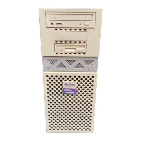
Sun Microsystems Ultra 30 Service Manual (248 pages)
Brand:
Sun Microsystems
| Category:
Desktop
| Size: 6 MB
Table of Contents
Table of Contents
3
Table of Contents
17
Preface
19
How this Book Is Organized
19
TABLE P-1 Document Organization
19
Product Description
19
UNIX Commands
20
Typographic Conventions
21
Shell Prompts
21
TABLE P-3 Shell Prompts
21
Related Documents
22
Sun Documentation on the Web
23
Sun Welcomes Your Comments
23
1 Product Description
25
I/O Devices
26
FIGURE 1-1 Sun Ultra 30 Desktop Workstation
26
TABLE 1-1 Supported I/O Devices
26
System Unit Features
27
FIGURE 1-2 System Unit Front View
27
FIGURE 1-3 System Unit Rear View
28
System Unit Components
29
2 Sunvts Overview
31
Sunvts Description
31
Sunvts Operation
31
Sunvts Operation
32
TABLE 2-1 Sunvts Documentation
32
3 Power-On Self-Test
33
POST Overview
33
Table
33
Pre-POST Preparation
34
Setting up a Tip Connection
34
FIGURE 3-1 Setting up a Tip Connection
35
Verifying the Baud Rate
36
Initializing POST
36
Maximum and Minimum Levels of POST
37
FIGURE 3-2 Sun Type-5 Keyboard
37
Diag-Level Variable Set to Max
38
Block Memory Addr Test INFO: 0MB Bank
41
ECC Memory Addr Test INFO: 0MB Bank
41
Memory Addr W/ Ecache Test INFO: 0MB Bank
41
Memory RAM Test INFO: 0MB Bank
41
Diag-Level Variable Set to Min
44
INFO: 0MB Bank
45
INFO: 0MB Bank
46
INFO: 64MB Bank
47
INFO: 64MB Bank
48
POST Progress and Error Reporting
50
TABLE 3-2 Keyboard LED Patterns
51
Bypassing POST
52
Additional Keyboard Control Commands
52
System and Keyboard Leds
52
Motherboard Test
53
4 Troubleshooting Procedures
55
Power-On Failure
55
Video Output Failure
56
Hard Drive or CD-ROM Drive Failure
57
TABLE 4-1 Internal Drives Identification
57
Power Supply Test
58
FIGURE 4-1 Power Supply Connector J2901
59
FIGURE 4-2 Power Supply Connector J2902
59
TABLE 4-2 Power Supply Connector J2901 Pin Assignments
59
TABLE 4-3 Power Supply Connector J2902 Pin Assignments
59
DIMM Failure
60
Openboot PROM On-Board Diagnostics
61
TABLE 4-5 DIMM Physical Memory Addresses
61
Watch-Clock
61
Watch-Net and Watch-Net-All
62
Probe-Scsi and Probe-Scsi-All
63
TABLE 4-6 Selected OBP On-Board Diagnostic Tests
64
Test Alias Name, Device Path, -All
64
To Initialize the UPA Graphics Card Diagnostic
65
UPA Graphics Card
65
Openboot Diagnostics
66
To Initialize the Obdiag Menu
66
Pci/Pcio
70
Ebus DMA/TCR Registers
71
Ethernet
71
Keyboard
72
Floppy
73
Mouse
73
Parallel Port
74
Serial Port a
74
Serial Port B
75
Nvram
76
Audio
77
Scsi
77
All above
78
To Recover the Original N1Fsvram Variable Settings
80
5 Safety and Tool Requirements
83
Safety Requirements
83
Symbols
83
Safety Precautions
84
Modification to Equipment
84
Placement of a Sun Product
84
Electrostatic Discharge
85
Lithium Battery
85
Power Cord Connection
85
Tools Required
85
6 Power on and off
87
Powering on the System Unit
87
FIGURE 6-1 System Power on (Front Panel)
88
FIGURE 6-2 Sun Type-5 Keyboard
88
Powering off the System Unit
89
FIGURE 6-3 System Power off (Front Panel)
90
7 Internal Access
91
Removing the Side Access Cover
91
FIGURE 7-1 Lock Block Location
92
FIGURE 7-2 Removing the Side Access Cover
93
Attaching the Wrist Strap
94
Replacing the Side Access Cover
95
FIGURE 7-3 Attaching the Wrist Strap
95
FIGURE 7-4 Replacing the Side Access Cover
96
8 Major Subassemblies
97
Power Supply
97
Removing the Power Supply
98
FIGURE 8-1 Removing and Replacing the Power Supply (Part 1 of 2)
99
FIGURE 8-2 Removing and Replacing the Power Supply (Part 2 of 2)
100
Replacing the Power Supply
100
PCI Fan Assembly
101
Removing the PCI Fan Assembly
101
FIGURE 8-3 Removing and Replacing the PCI Fan Assembly
102
Replacing the PCI Fan Assembly
103
Hard Drive Bay with SCSI Assembly
103
Removing the SCSI Drive Bay
103
FIGURE 8-4 Removing and Replacing the SCSI Drive Bay
105
Replacing the SCSI Drive Bay
105
Cable Assemblies
106
Removing the Peripheral Power Cable Assembly
106
Replacing the Peripheral Power Cable Assembly
107
Removing the Diskette Drive Cable Assembly
108
Removing the UPA Graphics Card Cable Assembly
109
Replacing the Diskette Drive Cable Assembly
109
FIGURE 8-5 Removing and Replacing the UPA Graphics Card Cable Assembly
111
Replacing the UPA Graphics Card Cable Assembly
112
EMI Filler Panels
112
Figure
113
FIGURE 8-6 Removing and Replacing the Bezel EMI Filler Panel
113
Removing an EMI Filler Panel
113
Replacing an EMI Filler Panel
114
Chassis Foot
114
FIGURE 8-7 Removing and Replacing the RMA EMI Filler Panel
114
Removing the Chassis Foot
114
FIGURE 8-8 Removing and Replacing the Chassis Foot
115
Replacing the Chassis Foot
115
Speaker Assembly
116
Removing the Speaker Assembly
116
Replacing the Speaker Assembly
117
DC Switch Assembly
118
Removing the DC Switch Assembly
118
FIGURE 8-10 Removing and Replacing the DC Switch Assembly
120
Replacing the DC Switch Assembly
120
Shroud Assembly
121
One-Piece Shroud Assembly
121
FIGURE 8-11 Removing and Replacing the One-Piece Shroud Assembly (Part 1 of 2)
122
Removing the One-Piece Shroud Assembly
122
FIGURE 8-12 Removing and Replacing the One-Piece Shroud Assembly (Part 2 of 2)
123
Replacing the One-Piece Shroud Assembly
123
Removing the Two-Piece Shroud Assembly
124
Two-Piece Shroud Assembly
124
FIGURE 8-13 Removing and Replacing the Two-Piece Shroud Assembly
125
Replacing the Two-Piece Shroud Assembly
126
Two-Piece Shroud Fan Assembly
126
Removing the Two-Piece Shroud Fan Assembly
127
FIGURE 8-14 Removing and Replacing the Two-Piece Shroud Fan Assembly
128
Replacing the Two-Piece Shroud Fan Assembly
128
9 Storage Devices
131
Hard Drive
131
Removing a Hard Drive
131
FIGURE 9-1 Removing and Replacing a Hard Drive
133
Replacing a Hard Drive
133
Removable Media Assembly Drive
134
Removing the RMA
134
FIGURE 9-2 Removing and Replacing the RMA Drive (Part 1 of 2)
135
FIGURE 9-3 Removing and Replacing the RMA Drive (Part 2 of 2)
136
Removing a CD-ROM Drive or 4-MM/8-MM Tape Drive
136
Removing a Diskette Drive
137
Replacing a CD-ROM Drive or 4-MM/8-MM Tape Drive
137
Replacing a Diskette Drive
137
Replacing the RMA
138
10 Motherboard and Component Replacement
139
CPU Module
139
Removing the CPU Module
140
FIGURE 10-1 Removing and Replacing the CPU Module
141
Replacing the CPU Module
141
Nvram/Tod
142
Removing the NVRAM/TOD
142
FIGURE 10-2 Removing and Replacing the NVRAM/TOD
143
Replacing the NVRAM/TOD
143
PCI Card
144
Removing a PCI Card
144
FIGURE 10-3 Removing and Replacing a PCI Card
145
Replacing a PCI Card
146
UPA Graphics Card
147
Removing a UPA Graphics Card
147
FIGURE 10-4 Removing and Replacing a UPA Graphics Card
148
Replacing a UPA Graphics Card
149
DIMM
150
TABLE 10-1 DIMM Installation Locations
150
FIGURE 10-5 DIMM Ejection Lever
151
Removing a DIMM
151
FIGURE 10-6 Removing and Replacing a DIMM
152
Replacing a DIMM
152
Audio Card
154
Removing the Audio Card
154
Replacing the Audio Card
155
Motherboard
156
FIGURE 10-7 Removing and Replacing the Audio Card
156
Removing the Motherboard
157
FIGURE 10-8 Removing and Replacing the Motherboard (Part 1 of 2)
159
FIGURE 10-9 Removing and Replacing the Motherboard (Part 2 of 2)
160
Replacing the Motherboard
160
FIGURE 10-10 Location of the Motherboard Serial Port Jumpers
161
TABLE 10-2 Motherboard Serial Port Jumpers J2604 and J2605
161
FIGURE 10-11 Identifying Jumper Pins
162
11 Illustrated Parts List
165
Product Specifications
169
Physical Specifications
169
TABLE A-1 Ultra 30 Physical Specifications
169
Electrical Specifications
170
Environmental Requirements
170
TABLE A-2 Ultra 30 Electrical Specifications
170
TABLE A-3 Ultra 30 Environmental Requirements
170
Signal Descriptions
171
Keyboard/Mouse and Serial Ports a and B
171
Keyboard/Mouse Connector
171
FIGURE B-1 Keyboard/Mouse Connector Pin Configuration
172
Serial Port a and B Connectors
172
TABLE B-1 Keyboard/Mouse Connector Pin Assignments
172
FIGURE B-2 Serial Port a and B Connector Pin Configurations
173
TABLE B-2 Serial Port a and B Connector Pin Assignments
173
Twisted-Pair Ethernet Connector
175
Ultrascsi Connector
176
FIGURE B-3 TPE Connector Pin Configuration
176
TABLE B-3 TPE Connector Pin Assignments
176
FIGURE B-4 Ultrascsi Connector Pin Configuration
177
TABLE B-4 Ultrascsi Connector Pin Assignments
177
Audio Connectors
180
FIGURE B-5 Audio Connector Configuration
180
TABLE B-5 Audio Connector Line Assignments
180
Parallel Port Connector
181
FIGURE B-6 Parallel Port Connector Pin Configuration
181
TABLE B-6 Parallel Port Connector Pin Assignments
181
Media Independent Interface Connector
183
TABLE B-7 MII Connector Pin Assignments
183
UPA Graphics Card Connector
185
TABLE B-8 UPA Graphics Card Connector Pin Assignments
186
Functional Description
187
System Unit
187
Upa
190
TABLE C-1 UPA Port Identification Assignments
190
PCI Bus
191
U2P Asic
191
Pcio Asic
192
Symbios 53C875 SCSI Controller
192
Ultrasparc II Processor
192
Memory System
193
DIMM
197
TABLE C-2 DIMM Pair-To-U Number
198
TABLE C-3 Physical Address Map to DIMM Pair (Non-Interleave
198
Graphics Card Features
199
Memory System Timing
199
TABLE C-4 Physical Address Maps to DIMM Pair (Interleave
199
Graphics Card Performance
200
Peripherals
200
CD-ROM Drive
201
Diskette Drive
201
Hard Drives
204
Optional 4-MM or 8-MM Tape Drive
204
TABLE C-6 Supported Hard Drives
204
Keyboard and Mouse Port
205
Keyboard and Mouse, Diskette, and Parallel Port
205
Diskette Port
206
Parallel Port
206
Electrical Characteristics
207
Serial Port
207
Serial Port Components
207
Serial Port Functions
208
Asynchronous Rates
209
EIA Levels
209
Slew Rate and Cable Length
209
Synchronous Rates
209
Automatic Negotiation
210
Ethernet
210
External Cables
210
External Transceivers
210
Connectors
211
MII Port Timing
212
MII Power
212
Audio Card and Connector
213
TABLE C-7 Major Features of the Audio Card
213
Scsi
214
Host Adapter
215
External Cables
216
Internal SCSI Subassembly
216
Supported Target Devices
216
TABLE C-8 SCSI Subsystem Supported Target Devices
216
SCSI ID Selection
217
Asic
218
Sc_Up
218
Pcio
219
U2P
219
Ultrabmx
219
Fbc
220
Risc
220
Superio
220
Power Supply
221
TABLE C-9 Power Supply Output Voltages
221
Control Signals
222
ON/OFF Functionality
222
Remote Enable Poweron and Poweroff
222
TABLE C-10 Power Supply Control Signals
222
System Unit Power Budget
223
TABLE C-11 Power Estimate (3.3-Ns CPU Module
223
Pci Cards
224
TABLE C-16 Power Estimates for the Storage Devices
225
Built-In Speaker
226
Microphone
227
Standard System Facilities
227
Motherboard
227
Serial Port Jumpers
230
TABLE C-18 Serial Port Jumper Settings
230
Enclosure
231
Enclosure Basics
231
Flash PROM Jumpers
231
TABLE C-19 Flash PROM Jumper Settings
231
Agency Compliance
232
Enclosure Features
232
Environmental Compliance
232
System Unit Features
245
Advertisement
Sun Microsystems Ultra 30 Reference Manual (58 pages)
Brand:
Sun Microsystems
| Category:
Desktop
| Size: 0 MB
Table of Contents
Table of Contents
3
Figures
7
How this Book Is Organized
11
Preface
11
Related Documents
12
Sun Welcomes Your Comments
12
Back Panel Connectors
13
Connector Layout
13
FIGURE 1-1 Back Panel Switches and Connectors
14
FIGURE 1-2 DB-25 Serial Connectors
15
Serial Connectors
15
FIGURE 1-3 DB-25 Parallel Connector
16
Parallel Connector
16
FIGURE 1-4 DIN-8 Keyboard/Mouse Connector
17
Keyboard/Mouse Connector
17
FIGURE 1-5 40-Pin Miniature-D MII Connector
18
Media Independent Interface (MII) Connector
18
MII Cable-Type Connectivity
19
External Cable Lengths
20
External Transceivers
20
TPE Cable-Type Connectivity
21
Twisted-Pair Ethernet (TPE) Connector
21
External Utp-5 Cable Lengths
22
SCSI Connector
22
SCSI Cabling and Configuration
24
SCSI Cabling Procedure
24
SCSI Implementation
24
SCSI-2 (Fast Wide SCSI) External Devices
25
Table
25
Audio Ports
27
FIGURE 1-9 Audio Port Locations
27
Ground
27
Table
27
Audio Specifications
28
Graphics Card 13W3 Video Connector
29
Ground
29
Ground
30
10BASE-T Twisted-Pair Ethernet Link Test
31
Overview
31
100 Meters
32
109 Yards
32
FIGURE 2-1 Hosts and Hub in a Local Area Network
32
Technical Discusssion
33
Moves and Changes
34
Troubleshooting
34
Checking or Disabling the Link Test
35
Enabling the Link Test
35
Modem Setup Specifications
37
Setting up the Modem
37
Serial Port Speed Change
38
Cable
39
Modem Switch Settings (at Commands)
39
Recommendations
39
Main Logic Board Jumpers
41
FIGURE 4-1 Jumper Locations on the Main Logic Board
42
Flash PROM Jumpers
43
Identifying Jumpers
43
Serial Port Jumpers
44
Ultrasparc Module Clocking Select Jumper
45
System Specifications
47
Environmental Specifications
48
Power Specifications
48
Physical Specifications
50
FIGURE 5-3 PCI Card Slot Locations on the System Unit Back Panel
53
Sun Microsystems Ultra 30 Installation Manual (61 pages)
Brand:
Sun Microsystems
| Category:
Server
| Size: 4 MB
Table of Contents
Operating
1
Installation Guide
1
Table of Contents
3
Operating and Service Positions
12
Opening the System Unit
14
Installing Dimms
16
Changing the RS-423/232 Jumpers
20
Installing the Hard Disk Drive
24
Installing the Diskette Drive or Accessory Device
30
Installing the CD-ROM Drive or Tape Drive
36
Installing UPA Graphics Cards or PCI Cards
42
Closing the System Unit
46
DIMM Installation Guidelines
48
DIMM Banks and Slot Pairs
50
PCI Card Slot Operating Frequencies
52
What's Next
54
Safety Agency Compliance
56
Inhalt
12
Betriebs- und Wartungsposition
12
Lägen För Drift Och Service
12
Öffnen der Systemeinheit
14
Ppna Systemenheten
14
Installieren der Dimms
16
Umstecken der RS-423/232-Jumper
20
Installieren des Festplattenlaufwerks
24
Installieren des Diskettenlaufwerks oder Zusatzgeräts
30
Installieren des CD-ROM- oder Bandlaufwerks
36
Installieren von UPA-Grafikkarten oder PCI-Karten
42
Schließen der Systemeinheit
46
Stänga Systemenheten
46
Hinweise zur DIMM-Installation
48
Installationsanvisningar För DIMM-Moduler
48
DIMM-Bänke und Steckplatzpaare
50
Betriebsfrequenzen der PCI-Karten-Steckplätze
52
Driftsfrekvenser För Pci-Kortplatser
52
Wie es Weitergeht
54
Gå Vidare
54
Einhaltung der Sicherheitsvorschriften
57
Advertisement
Sun Microsystems Ultra 30 Installation Manual (63 pages)
Brand:
Sun Microsystems
| Category:
Desktop
| Size: 4 MB
Table of Contents
Operating
1
Installation Guide
1
Table of Contents
3
Declaration of Conformity
10
Operating and Service Positions
12
Opening the System Unit
14
Installing Dimms
16
Changing the RS-423/232 Jumpers
20
Installing the Hard Disk Drive
24
Installation de L'unité de Disque Dur
24
Installing the Diskette Drive or Accessory Device
30
Installing the CD-ROM Drive or Tape Drive
36
Installing UPA Graphics Cards or PCI Cards
42
Closing the System Unit
46
DIMM Installation Guidelines
48
Instructions D'installation des Modules DIMM
48
DIMM Banks and Slot Pairs
50
PCI Card Slot Operating Frequencies
52
What's Next
54
Safety Agency Compliance
56
Des
12
Positions de Fonctionnement Et de Manutention
12
Ouverture de L'unité Système
14
Installation des Modules DIMM
16
Changement des Cavaliers RS423/232
20
Installation du Lecteur de Disquette Ou D'un Périphérique Connexe
30
Installation du Lecteur de CD-ROM Ou du Lecteur de Bande
36
Installation de Cartes Graphiques UPA Ou de Cartes PCI
42
Fermeture de L'unité Système
46
Rangées Et Paires D'emplacements des Modules DIMM
50
Fréquences de Fonctionnement des Emplacements de Cartes PCI
52
Informations Supplémentaires
54
Conformité Aux Normes de Sécurité
57
Conformità alle Norme DI Sicurezza
58
Normativas de Seguridad
59
Sun Microsystems Ultra 30 Installation Manual (32 pages)
Brand:
Sun Microsystems
| Category:
Desktop
| Size: 2 MB
Table of Contents
Table of Contents
3
Sun Ultra 30/60/80 Systems Rackmount Installation Guide
5
Preparing the Site
5
Preparing the Rackmounting Tray
7
Preparing the Ultra 30/60 System
14
Installing the Ultra 30/60 System
18
Preparing the Ultra 80 System
24
Installing the Ultra 80 System
28
Advertisement
Related Products
Sun Microsystems Ultra 24
Sun Microsystems Ultra 25
Sun Microsystems Sun Ultra 27
Sun Microsystems Sun Ultra 450
Sun Microsystems Ultra 10 EMI
Sun Microsystems Ultra 5
Sun Microsystems Ultra 10
Sun Microsystems Sun Ultra 2 Series
Sun Microsystems Ultra 80
Sun Microsystems Ultra 1 Series
Sun Microsystems Categories
Server
Storage
Desktop
Computer Hardware
Adapter
More Sun Microsystems Manuals
Login
Sign In
OR
Sign in with Facebook
Sign in with Google
Upload manual
Upload from disk
Upload from URL