Sign In
Upload
Manuals
Brands
Omron Manuals
Controller
R88D-1SN10H-ECT
Omron R88D-1SN10H-ECT Manuals
Manuals and User Guides for Omron R88D-1SN10H-ECT. We have
2
Omron R88D-1SN10H-ECT manuals available for free PDF download: User Manual
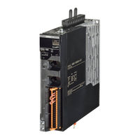
Omron R88D-1SN10H-ECT User Manual (974 pages)
AC Servomotors/Servo Drives
Brand:
Omron
| Category:
Controller
| Size: 46.81 MB
Table of Contents
Introduction
3
Manual Structure
4
Manual Configuration
6
Sections in this Manual
7
Table of Contents
8
Terms and Conditions Agreement
18
Safety Precautions
20
Items to Check after Unpacking
31
Related Manuals
42
Terminology
45
Revision History
47
Features and System Configuration
49
Outline
50
Features of 1S-Series Servo Drives
50
Ethercat
51
Object Dictionary
52
System Configuration
53
Names and Functions
54
Servo Drive Part Names
54
Servo Drive Functions
62
Servomotor Part Names
65
Servomotor Functions
67
Shield Clamp Part Names
68
System Block Diagram
69
Applicable Standards
77
EU Directives
77
UL and Cul Standards
78
Korean Radio Regulations (KC)
79
Semi F47
79
Australian EMC Labeling Requirements (RCM)
80
EAC Requirements
80
Unit Versions
81
Confirmation Method
81
Unit Versions and Sysmac Studio Versions
81
Procedures to Start Operation
82
Overall Procedure
82
Procedure Details
84
Models and External Dimensions
89
Servo System Configuration
90
How to Read Model Numbers
92
Servo Drive
92
Servomotor
93
Encoder Cable
94
Motor Power Cable Without Brake Wire
95
Motor Power Cable with Brake Wire
96
Decelerator
97
Model Tables
99
Servo Drive Model Table
99
Servomotor Model Tables
100
Servo Drive and Servomotor Combination Tables
105
Decelerator Model Tables
107
Servomotor and Decelerator Combination Tables
111
Cable and Connector Model Tables
113
External Regeneration Resistor and External Regeneration Resistance Unit Model Tables
121
External Dynamic Brake Resistor Model Table
122
Reactor Model Table
122
Noise Filter Model Table
123
External and Mounting Dimensions
124
Servo Drive Dimensions
124
Servomotor Dimensions
131
Cable Outlet Direction
187
Cable Wiring Dimension for a Case of Motor Installing
188
Decelerator Dimensions
190
Dimensions of External Regeneration Resistors and External Regeneration Resistance Units
207
Dimensions of External Dynamic Brake Resistors
208
Reactor Dimensions
209
Noise Filter Dimensions
218
Specifications
221
Servo Drive Specifications
223
General Specifications
223
Characteristics
225
Ethercat Communications Specifications
233
Main Circuit and Motor Connections
234
Control I/O Connector (CN1) Specifications
247
Control Input Circuits
250
Control Input Details
250
Control Output Circuits
251
Control Output Details
252
Encoder Pulse Output Specifications
252
Safety I/O Specifications
253
Brake Interlock Connector (CN12) Specifications
255
Encoder Connector (CN2) Specifications
255
Ethercat Communications Connector (RJ45) Specifications
256
USB Connector (CN7) Specifications
256
Power on Sequence
257
Overload Characteristics (Electronic Thermal Function)
258
Servomotor Specifications
263
General Specifications
263
Encoder Specifications
264
Characteristics
265
Decelerator Specifications
290
Cable and Connector Specifications
297
Encoder Cable Specifications
297
Motor Power Cable Specifications
304
Combination of Power Cable and Extension Cable
337
Resistance to Bending of Flexible Cable
338
Connector Specifications
340
Ethercat Communications Cable Specifications
344
Specifications of External Regeneration Resistors and External Regeneration Resistance Units
347
General Specifications
347
Regeneration Resistance Units
347
Characteristics
348
External Regeneration Resistance Unit Specifications
350
External Dynamic Brake Resistor
352
General Specifications
352
Characteristics
352
Reactor Specifications
353
General Specifications
353
Characteristics
353
Terminal Block Specifications
354
Noise Filter Specifications
355
General Specifications
355
Characteristics
356
Terminal Block Specifications
357
Configuration and Wiring
359
Installation Conditions
360
Servo Drive Installation Conditions
360
Servomotor Installation Conditions
365
Decelerator Installation Conditions
369
External Regeneration Resistor and External Regeneration Resistance Unit Installation Conditions
372
Footprint-Type Noise Filter Installation Conditions
373
External Dynamic Brake Resistor Installation Condition
374
Wiring
375
Peripheral Equipment Connection Examples
376
Procedure for Wiring Terminal Block and Procedure for Mounting Shield Clamp to Servo Drive
392
Connector Attachment Procedure
398
Procedure for Change of Cable Outlet Direction for Connector Type M23 or M40
402
Terminal Block Wiring Procedure for Footprint-Type Noise Filter
404
Wiring Conforming to EMC Directives
405
Peripheral Equipment Connection Examples
406
Selecting Connection Component
420
Regenerative Energy Absorption
430
Calculating the Regenerative Energy
430
Servo Drive Regeneration Absorption Capacity
433
Regenerative Energy Absorption by an External Regeneration Resistance Device
434
Connecting an External Regeneration Resistor
435
Adjustment for Large Load Inertia
436
Machine Accuracy for Servomotor
437
Ethercat Communications
439
Display Area and Settings
440
Node Address Setting
440
Status Indicators
441
Structure of the CAN Application Protocol over Ethercat
443
Ethercat State Machine
444
Process Data Objects (Pdos)
445
PDO Mapping Settings
445
Sync Manager PDO Assignment Settings
446
Fixed PDO Mapping
446
Variable PDO Mapping
449
Sync Manager PDO Mapping Assignment Settings
450
Service Data Objects (Sdos)
451
Synchronization Mode and Communications Cycle
452
Distributed Clock (DC) Mode
452
Free-Run Mode
452
Emergency Messages
453
Sysmac Device Features
454
Cable Redundancy Function
458
Objects Requiring Settings
458
Description of Operation
458
Procedure of Checking Operation
459
Slave Communications Statuses When Cable Redundancy Function Is Used
461
Relation between the Network Configuration Information and the Actual Configuration
462
Basic Control Functions
465
Outline of Control Functions
466
Basic Control and Control Methods
466
Control Method
467
Control Blocks
469
Block Diagram for Position Control
469
Block Diagram for Velocity Control
471
Block Diagram for Torque Control
473
Cyclic Synchronous Position Mode
474
Cyclic Synchronous Velocity Mode
476
Cyclic Synchronous Torque Mode
478
Profile Position Mode
480
Profile Velocity Mode
485
Homing Mode
488
Connecting with OMRON Controllers
489
Applied Functions
493
General-Purpose Input Signals
495
Objects Requiring Settings
496
Default Setting
498
Function Input Details
499
General-Purpose Output Signals
500
Objects Requiring Settings
500
Default Setting
502
Function Output Details
503
Drive Prohibition Functions
507
Objects Requiring Settings
507
Description of Operation
508
Software Position Limit Functions
509
Operating Conditions
509
Objects Requiring Settings
509
Description of Operation
510
Backlash Compensation
512
Operating Conditions
512
Objects Requiring Settings
512
Description of Operation
513
Brake Interlock
514
Objects Requiring Settings
514
Description of Operation
516
Operation Timing
517
Electronic Gear Function
521
Objects Requiring Settings
521
Operation Example
522
Torque Limit Switching
523
Operating Conditions
523
Objects Requiring Settings
523
Torque Limit Switching Method
524
Soft Start
525
Objects Requiring Settings
525
Soft Start Acceleration/Deceleration Time
525
Velocity Command First-Order Lag Filter
526
Gain Switching Function
527
Objects Requiring Settings
527
Mode Selection
529
Gain Switching in Position Control
530
Touch Probe Function (Latch Function)
531
Related Objects
531
Trigger Signal Settings
533
Operation Sequence
534
Encoder Dividing Pulse Output Function
535
Objects Requiring Settings
536
Dividing Ratio
536
Output Reverse Selection
537
Z-Phase Output
537
Dynamic Brake
538
Operating Conditions
538
Objects Requiring Settings
538
Description of Operation
539
Communications Error Period Command Correction Function
542
Operating Conditions
542
Operation Example
542
Safety Function
545
Safe Torque off Function
546
STO Function Via Safety Input Signals
548
I/O Signal Specifications
548
Operation Example
550
Connection Example
551
STO Function Via Ethercat Communications
554
Connection and Setting
554
Operation Example
556
Connection Example
558
Details on Servo Parameters
561
Object Description Format
564
3001 Hex: Machine
572
3002 Hex: Optimized Parameters
573
3011 Hex: Position Command Filter
577
3012 Hex: Damping Control
578
3020 Hex: Velocity Command
582
3021 Hex: Velocity Command Filter
583
3030 Hex: Torque Command
584
3031 Hex: Velocity Limit in Torque Control
584
3040 Hex: Profile Command
585
Control Method Objects
588
3112 Hex: ODF Velocity Feed-Forward
588
3113 Hex: ODF Torque Feed-Forward
589
3120 Hex: TDF Position Control
590
3121 Hex: TDF Velocity Control
591
Control Loop Objects
593
3210 Hex: Internal Position Command
593
3213 Hex: 1St Position Control Gain
595
3214 Hex: 2Nd Position Control Gain
596
3220 Hex: Internal Velocity Command
596
3221 Hex: Velocity Detection
597
3222 Hex: Gain Switching in Velocity Control
598
3223 Hex: 1St Velocity Control Gain
598
3224 Hex: 2Nd Velocity Control Gain
599
3230 Hex: Internal Torque Command
600
3231 Hex: Torque Detection
600
3232 Hex: Filter Switching in Torque Control
600
3233 Hex: 1St Torque Command Filter
601
3234 Hex: 2Nd Torque Command Filter
602
Torque Output Setting Objects
603
3310 Hex: Torque Compensation
603
3320 Hex: Adaptive Notch Filter
605
3330 Hex: Torque Limit
614
Homing Objects
616
Applied Function Objects
620
3B10 Hex: Drive Prohibition
620
3B11 Hex: Software Position Limit
621
3B50 Hex: Position Detection Function
633
3B51 Hex: Positioning Completion Notification
633
3B52 Hex: Positioning Completion Notification 2
634
3B60 Hex: Speed Detection Function
635
3B70 Hex: Vibration Detection
636
3B71 Hex: Runaway Detection
637
3B80 Hex: Load Characteristic Estimation
638
Error- and Warning-Related Objects
641
4000 Hex: Error Full Code
641
4021 Hex: Warning Output 1 Setting
645
4022 Hex: Warning Output 2 Setting
646
4030 Hex: Information Customization
647
Monitoring-Related Objects
648
4110 Hex: Monitor Data Via PDO
648
4120 Hex: Ethercat Communications Error Count
649
4130 Hex: Safety Status Monitor
649
4150 Hex: Overload
655
Display-Related Objects
657
Power Device-Related Objects
658
4320 Hex: Main Circuit Power Supply
659
External Device-Related Objects
661
4412 Hex: Motor Advanced Setting
662
Encoder-Related Objects
664
4601 Hex: Function Input
668
4602 Hex: Function Output
670
4604 Hex: Control Input Change Count
671
4610 Hex: Brake Interlock Output
673
4620 Hex: Encoder Dividing Pulse Output
674
General-Purpose Input Setting Objects
676
Setting
676
4630 Hex: Positive Drive Prohibition Input
677
4631 Hex: Negative Drive Prohibition Input
677
4633 Hex: External Latch Input 2
678
4634 Hex: Home Proximity Input
678
4635 Hex: Positive Torque Limit Input
678
4636 Hex: Negative Torque Limit Input
679
4637 Hex: Error Stop Input
679
4638 Hex: Monitor Input 1
679
4639 Hex: Monitor Input 2
680
Hex: Monitor Input 3
680
Hex: Monitor Input 4
680
Hex: Monitor Input 5
681
Hex: Monitor Input 6
681
Hex: Monitor Input 7
681
Hex: Monitor Input 8
682
General-Purpose Output Setting Objects
683
Setting
683
4650 Hex: Error Output
684
4651 Hex: Servo Ready Output
684
4652 Hex: Positioning Completion Output 1
684
4653 Hex: Positioning Completion Output 2
685
4654 Hex: Velocity Attainment Detection Output
685
4655 Hex: Torque Limit Output
685
4656 Hex: Zero Speed Detection Output
686
4657 Hex: Velocity Conformity Output
686
4658 Hex: Warning Output 1
686
4659 Hex: Warning Output 2
687
Hex: Velocity Limiting Output
687
Hex: Error Clear Attribute Output
687
Hex: Remote Output 3
688
Hex: Zone Notification Output 1
689
4660 Hex: Zone Notification Output 2
689
4661 Hex: Position Command Status Output
689
4662 Hex: Distribution Completed Output
690
4663 Hex: External Brake Interlock Output
690
Operational Procedure
692
Preparing for Operation
693
Items to Check before Turning on the Power Supply
693
Turning on the Power Supply
694
Checking the Displays
695
Absolute Encoder Setup
697
Setting up an Absolute Encoder from the Sysmac Studio
697
Test Run
698
Preparations for Test Run
698
Test Run Via USB Communications from the Sysmac Studio
699
Adjustment Functions
701
Outline of Adjustment Functions
703
Adjustment Methods
703
Adjustment Procedure
704
Easy Tuning
706
Objects that Are Set
706
Executing Easy Tuning
708
Advanced Tuning
709
Objects that Are Set
709
Executing Advanced Tuning
710
Manual Tuning
711
Objects that Are Set
711
Executing Manual Tuning
711
Data Trace
712
Fft
713
Damping Control
714
Objects Requiring Settings
714
Operating Procedure
716
Setting Frequency with Sysmac Studio
717
Load Characteristic Estimation
718
Objects Requiring Settings
719
Setting Load Characteristic Estimation Function
720
Adaptive Notch Filter
721
Objects Requiring Settings
721
Operating Procedure
722
Notch Filters
723
Objects Requiring Settings
724
Notch Filter Width and Depth
725
Friction Torque Compensation Function
726
Operating Conditions
726
Objects Requiring Settings
726
Operation Example
727
Feed-Forward Function
729
Feed-Forward Control in TDF Control
729
Feed-Forward Control in ODF Control
731
Troubleshooting
733
Actions for Problems
734
Preliminary Checks When a Problem Occurs
734
Precautions When a Problem Occurs
735
Replacing the Servomotor or Servo Drive
736
Warnings
738
Related Objects
738
Warning List
740
Errors
742
Error List
742
Deceleration Stop Operation at Errors
745
Information
746
Related Objects
746
Information List
746
Troubleshooting
747
Troubleshooting Using Error Displays
748
Troubleshooting Using al Status Codes
770
Troubleshooting Using the Operation State
774
Maintenance and Inspection
781
Periodic Maintenance
782
Servo Drive Lifetime
783
Servomotor Lifetime
784
Method for Broken Ring Maintenance and Inspection
785
Appendices
787
Cia 402 Drive Profile
788
A-1-1 Controlling the State Machine of the Servo Drive
788
A-1-2 Modes of Operation
790
A-1-3 Modes of Operation and Applied/Adjustment Functions
791
A-1-4 Changing the Mode of Operation
791
A-1-5 Homing Mode Specifications
793
Coe Objects
798
A-2-1 Object Dictionary Area
798
A-2-2 Data Type
798
Object Description Format
799
A-2-4 Communication Objects
800
A-2-5 PDO Mapping Objects
806
A-2-6 Sync Manager Communication Objects
821
A-2-7 Manufacturer Specific Objects
824
Servo Drive Profile Object
827
A-2-9 Safety Function Objects
850
Object List
854
Sysmac Error Status Codes
886
A-4-1 Error List
886
A-4-2 Error Descriptions
899
Response Time in Ethercat Process Data Communications
964
A-5-1 Input Response Time
964
A-5-2 Output Response Time
964
Version Information
965
A-6-1 Relationship between Unit Versions and Sysmac Studio Versions
965
A-6-2 Functions that Were Added or Changed for each Unit Version
967
Advertisement
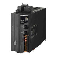
Omron R88D-1SN10H-ECT User Manual (828 pages)
AC Servomotors/Servo Drives
Brand:
Omron
| Category:
Controller
| Size: 34.05 MB
Table of Contents
Introduction
3
Manual Structure
4
Level
5
Manual Configuration
6
Sections in this Manual
7
Table of Contents
8
Terms and Conditions Agreement
18
Safety Precautions
20
Items to Check after Unpacking
31
Related Manuals
40
Terminology
42
Level
42
Revision History
44
Features and System Configuration
45
Outline
46
Features of 1S-Series Servo Drives
46
Ethercat
47
Object Dictionary
48
System Configuration
49
Names and Functions
50
Servo Drive Part Names
50
Servo Drive Functions
54
Servomotor Part Names
56
Servomotor Functions
57
System Block Diagram
58
Applicable Standards
62
EU Directives
62
UL and Cul Standards
63
Korean Radio Regulations (KC)
64
Semi F47
64
Australian EMC Labeling Requirements (RCM)
64
Unit Versions
65
Confirmation Method
65
Unit Versions and Sysmac Studio Versions
65
Procedures to Start Operation
66
Overall Procedure
66
Procedure Details
68
Servo System Configuration
74
How to Read Model Numbers
76
Servo Drive
76
Servomotor
77
Decelerator (Backlash: 3 Arcminutes Max.)
78
Decelerator (Backlash: 15 Arcminutes Max.)
79
Model Tables
80
Servo Drive Model Table
80
Servomotor Model Tables
81
Servo Drive and Servomotor Combination Tables
85
Decelerator Model Tables
86
Servomotor and Decelerator Combination Tables
89
Cable and Connector Model Tables
90
External Regeneration Resistor and External Regeneration Resistance Unit Model Tables
95
Reactor Model Table
96
Noise Filter Model Table
96
External and Mounting Dimensions
97
Servo Drive Dimensions
97
Servomotor Dimensions
101
Decelerator Dimensions
137
Dimensions of External Regeneration Resistors and External Regeneration Resistance Units
151
Reactor Dimensions
152
Noise Filter Dimensions
161
Specifications
165
Servo Drive Specifications
167
General Specifications
167
Characteristics
168
Ethercat Communications Specifications
172
Main Circuit and Motor Connections
173
Control I/O Connector (CN1) Specifications
178
Control Input Circuits
181
Control Input Details
182
Control Output Circuits
182
Control Output Details
182
Encoder Pulse Output Specifications
183
Safety I/O Specifications
184
Brake Interlock Connector (CN12) Specifications
185
Encoder Connector (CN2) Specifications
186
Ethercat Communications Connector (RJ45) Specifications
186
USB Connector (CN7) Specifications
187
Power on Sequence
187
Overload Characteristics (Electronic Thermal Function)
188
Servomotor Specifications
192
General Specifications
192
Encoder Specifications
193
Characteristics
194
Decelerator Specifications
212
Cable and Connector Specifications
217
Encoder Cable Specifications
217
Motor Power Cable Specifications
222
Resistance to Bending of Flexible Cable
248
Connector Specifications
250
Ethercat Communications Cable Specifications
254
Specifications of External Regeneration Resistors and External Regeneration Resistance Units
257
General Specifications
257
Regeneration Resistance Units
257
Characteristics
258
External Regeneration Resistance Unit Specifications
260
Reactor Specifications
261
General Specifications
261
Characteristics
261
Terminal Block Specifications
262
Noise Filter Specifications
263
General Specifications
263
Characteristics
264
Terminal Block Specifications
265
Section 4 Configuration and Wiring
268
Installation Conditions
268
Servo Drive Installation Conditions
268
Servomotor Installation Conditions
271
Decelerator Installation Conditions
275
External Regeneration Resistance Unit Installation Conditions
277
Footprint-Type Noise Filter Installation Conditions
278
Wiring
279
Peripheral Equipment Connection Examples
280
Terminal Block Wiring Procedure
290
Connector Attachment Procedure
292
Power/Brake Connector Attachment Procedure
293
Terminal Block Wiring Procedure for Footprint-Type Noise Filter
294
Wiring Conforming to EMC Directives
295
Peripheral Equipment Connection Examples
296
Selecting Connection Component
305
Regenerative Energy Absorption
311
Calculating the Regenerative Energy
311
Servo Drive Regeneration Absorption Capacity
314
Regenerative Energy Absorption by an External Regeneration Resistance Device
315
Connecting an External Regeneration Resistor
316
Adjustment for Large Load Inertia
317
Ethercat Communications
319
Section 5 Ethercat Communications
320
Display Area and Settings
320
Node Address Setting
320
Status Indicators
321
Structure of the CAN Application Protocol over Ethercat
323
Ethercat State Machine
324
Process Data Objects (Pdos)
325
PDO Mapping Settings
325
Sync Manager PDO Assignment Settings
326
Fixed PDO Mapping
326
Variable PDO Mapping
329
Sync Manager PDO Mapping Assignment Settings
330
Service Data Objects (Sdos)
331
Synchronization Mode and Communications Cycle
332
Distributed Clock (DC) Mode
332
Free-Run Mode
332
Emergency Messages
333
Sysmac Device Features
334
Basic Control Functions
339
Outline of Control Functions
340
Basic Control and Control Methods
340
Control Method
341
Control Blocks
343
Block Diagram for Position Control
343
Block Diagram for Velocity Control
345
Block Diagram for Torque Control
347
Cyclic Synchronous Position Mode
348
Cyclic Synchronous Velocity Mode
350
Cyclic Synchronous Torque Mode
352
Profile Position Mode
354
Profile Velocity Mode
359
Homing Mode
362
Connecting with OMRON Controllers
363
Applied Functions
367
General-Purpose Input Signals
369
Objects Requiring Settings
370
Default Setting
372
Function Input Details
373
General-Purpose Output Signals
374
Default Setting
376
Function Output Details
377
Drive Prohibition Functions
381
Objects Requiring Settings
381
Description of Operation
382
Software Position Limit Functions
383
Operating Conditions
383
Objects Requiring Settings
383
Description of Operation
384
Backlash Compensation
386
Operating Conditions
386
Objects Requiring Settings
386
Description of Operation
387
Brake Interlock
388
Objects Requiring Settings
388
Operation Timing
390
Electronic Gear Function
394
Objects Requiring Settings
394
Operation Example
395
Torque Limit Switching
396
Operating Conditions
396
Objects Requiring Settings
396
Torque Limit Switching Method
397
Soft Start
398
Objects Requiring Settings
398
Soft Start Acceleration/Deceleration Time
398
Velocity Command First-Order Lag Filter
399
Gain Switching Function
400
Objects Requiring Settings
400
Mode Selection
402
Gain Switching in Position Control
403
Touch Probe Function (Latch Function)
404
Related Objects
404
Trigger Signal Settings
406
Operation Sequence
407
Encoder Dividing Pulse Output Function
408
Objects Requiring Settings
409
Dividing Ratio
409
Output Reverse Selection
410
Z-Phase Output
410
Dynamic Brake
411
Operating Conditions
411
Objects Requiring Settings
411
Description of Operation
412
Safety Function
415
Section 8 Safety Function
416
Safe Torque off Function
416
STO Function Via Safety Input Signals
418
I/O Signal Specifications
418
Operation Example
420
Connection Example
421
STO Function Via Ethercat Communications
424
Connection and Setting
424
Operation Example
426
Connection Example
428
Details on Servo Parameters
431
Section 9 Details on Servo Parameters
434
Object Description Format
434
Common Control Objects
436
3001 Hex: Machine
442
3002 Hex: Optimized Parameters
443
Hex: Position Command
445
3011 Hex: Position Command Filter
447
3012 Hex: Damping Control
448
Hex: Damping Filter 1
449
Hex: Damping Filter 2
450
3020 Hex: Velocity Command
452
3021 Hex: Velocity Command Filter
453
3030 Hex: Torque Command
454
3031 Hex: Velocity Limit in Torque Control
454
3040 Hex: Profile Command
455
3041 Hex: Command Dividing Function
456
Control Method Objects
457
3112 Hex: ODF Velocity Feed-Forward
457
3113 Hex: ODF Torque Feed-Forward
458
3120 Hex: TDF Position Control
459
3121 Hex: TDF Velocity Control
460
Control Loop Objects
462
3210 Hex: Internal Position Command
462
3211 Hex: Position Detection
463
3212 Hex: Gain Switching in Position Control
463
3213 Hex: 1St Position Control Gain
464
3214 Hex: 2Nd Position Control Gain
465
3220 Hex: Internal Velocity Command
465
3221 Hex: Velocity Detection
466
3222 Hex: Gain Switching in Velocity Control
467
3223 Hex: 1St Velocity Control Gain
467
3224 Hex: 2Nd Velocity Control Gain
468
3230 Hex: Internal Torque Command
469
3231 Hex: Torque Detection
469
3232 Hex: Filter Switching in Torque Control
469
3233 Hex: 1St Torque Command Filter
470
3234 Hex: 2Nd Torque Command Filter
471
Torque Output Setting Objects
472
3320 Hex: Adaptive Notch Filter
474
Hex: 1St Notch Filter
475
Hex: 2Nd Notch Filter
477
Hex: 3Rd Notch Filter
479
Hex: 4Th Notch Filter
481
3330 Hex: Torque Limit
483
Homing Objects
485
Applied Function Objects
489
3B10 Hex: Drive Prohibition
489
3B11 Hex: Software Position Limit
490
B20 Hex: Stop Selection
492
B21 Hex: Deceleration Stop
496
3B31 Hex: Touch Probe 2
499
B40 Hex: Zone Notification 1
500
3B41 Hex: Zone Notification 2
501
3B50 Hex: Position Detection Function
502
3B51 Hex: Positioning Completion Notification
502
3B52 Hex: Positioning Completion Notification 2
503
3B60 Hex: Speed Detection Function
504
3B70 Hex: Vibration Detection
505
3B71 Hex: Runaway Detection
506
3B80 Hex: Load Characteristic Estimation
507
Error- and Warning-Related Objects
510
4000 Hex: Error Full Code
510
Hex: Warning Customization
511
4021 Hex: Warning Output 1 Setting
514
4022 Hex: Warning Output 2 Setting
515
4030 Hex: Information Customization
516
Monitoring-Related Objects
517
4110 Hex: Monitor Data Via PDO
517
4120 Hex: Ethercat Communications Error Count
518
4130 Hex: Safety Status Monitor
518
Hex: Safety Command Monitor 1
520
4132 Hex: Safety Command Monitor 2
521
Hex: Lifetime Information
522
4150 Hex: Overload
524
Display-Related Objects
526
Power Device-Related Objects
527
4310 Hex: Regeneration
527
4320 Hex: Main Circuit Power Supply
528
External Device-Related Objects
530
Encoder-Related Objects
532
I/O-Related Objects
535
4601 Hex: Function Input
536
4602 Hex: Function Output
538
Hex: Control Input Change Count
539
Hex: Control Output Change Count
540
Hex: Brake Interlock Output
541
Hex: Encoder Dividing Pulse Output
542
General-Purpose Input Setting Objects
544
Setting
544
4630 Hex: Positive Drive Prohibition Input
545
4631 Hex: Negative Drive Prohibition Input
545
4632 Hex: External Latch Input 1
545
4633 Hex: External Latch Input 2
546
4634 Hex: Home Proximity Input
546
4635 Hex: Positive Torque Limit Input
546
4636 Hex: Negative Torque Limit Input
547
4637 Hex: Error Stop Input
547
4638 Hex: Monitor Input 1
547
4639 Hex: Monitor Input 2
548
Hex: Monitor Input 4
548
Hex: Monitor Input 5
548
Hex: Monitor Input 6
549
Hex: Monitor Input 7
549
F Hex: Monitor Input 8
550
General-Purpose Output Setting Objects
551
Setting
551
4650 Hex: Error Output
552
4651 Hex: Servo Ready Output
552
4652 Hex: Positioning Completion Output 1
552
4653 Hex: Positioning Completion Output 2
553
4654 Hex: Velocity Attainment Detection Output
553
4655 Hex: Torque Limit Output
553
4656 Hex: Zero Speed Detection Output
554
4657 Hex: Velocity Conformity Output
554
4659 Hex: Warning Output 2
555
Hex: Velocity Limiting Output
555
Hex: Error Clear Attribute Output
555
Hex: Remote Output 1
556
Hex: Remote Output 2
556
Hex: Remote Output 3
556
Hex: Zone Notification Output 1
557
4660 Hex: Zone Notification Output 2
557
4661 Hex: Position Command Status Output
557
4662 Hex: Distribution Completed Output
558
Operation
559
Section 10 Operation
560
Operational Procedure
560
Preparing for Operation
561
Items to Check before Turning on the Power Supply
561
Turning on the Power Supply
562
Checking the Displays
563
Absolute Encoder Setup
565
Setting up an Absolute Encoder from the Sysmac Studio
565
Test Run
566
Preparations for Test Run
566
Test Run Via USB Communications from the Sysmac Studio
567
Adjustment Functions
569
Outline of Adjustment Functions
571
Adjustment Methods
571
Adjustment Procedure
572
Easy Tuning
574
Objects that Are Set
574
Executing Easy Tuning
576
Advanced Tuning
577
Objects that Are Set
577
Executing Advanced Tuning
578
Manual Tuning
579
Objects that Are Set
579
Executing Manual Tuning
579
Data Trace
580
Fft
581
Damping Control
582
Objects Requiring Settings
582
Operating Procedure
584
Setting Frequency with Sysmac Studio
585
Load Characteristic Estimation
586
Objects Requiring Settings
587
Setting Load Characteristic Estimation Function
588
Adaptive Notch Filter
589
Objects Requiring Settings
589
Operating Procedure
590
Notch Filters
591
Objects Requiring Settings
592
Notch Filter Width and Depth
593
Friction Torque Compensation Function
594
Operating Conditions
594
Objects Requiring Settings
594
Operation Example
595
Feed-Forward Function
597
Feed-Forward Control in TDF Control
597
Feed-Forward Control in ODF Control
599
Troubleshooting
601
Actions for Problems
602
Preliminary Checks When a Problem Occurs
602
Precautions When a Problem Occurs
603
Replacing the Servomotor or Servo Drive
604
Warnings
606
Related Objects
606
Warning List
608
Errors
610
Error List
610
Deceleration Stop Operation at Errors
612
Information
613
Related Objects
613
Information List
613
Troubleshooting
614
Troubleshooting Using Error Displays
614
Troubleshooting Using al Status Codes
634
Troubleshooting Using the Operation State
638
Maintenance and Inspection
645
Section 13 Maintenance and Inspection
646
Periodic Maintenance
646
Servo Drive Lifetime
647
Servomotor Lifetime
648
Appendices
649
Cia 402 Drive Profile
650
A-1-1 Controlling the State Machine of the Servo Drive
650
A-1-2 Modes of Operation
652
A-1-3 Modes of Operation and Applied/Adjustment Functions
653
A-1-4 Changing the Mode of Operation
653
A-1-5 Homing Mode Specifications
655
Coe Objects
660
A-2-1 Object Dictionary Area
660
A-2-2 Data Type
660
Object Description Format
661
A-2-4 Communication Objects
662
A-2-5 PDO Mapping Objects
668
A-2-6 Sync Manager Communication Objects
683
A-2-7 Manufacturer Specific Objects
686
Servo Drive Profile Object
689
A-2-9 Safety Function Objects
711
Object List
715
Sysmac Error Status Codes
746
A-4-1 Error List
746
A-4-2 Error Descriptions
757
Response Time in Ethercat Process Data Communications
819
A-5-1 Input Response Time
819
A-5-2 Output Response Time
819
Version Information
820
A-6-1 Relationship between Unit Versions and Sysmac Studio Versions
820
A-6-2 Functions that Were Added or Changed for each Unit Version
821
Advertisement
Related Products
Omron R88D-1SN10F-ECT
Omron R88D-1SN15F-ECT
Omron R88D-1SN15H-ECT
Omron R88D-1SN150H-ECT
Omron R88D-1SN150F-ECT
Omron R88D-1SN02L-ECT
Omron R88D-1SN01H-ECT
Omron R88D-1SN ECT Series
Omron R88D-1SN75F-ECT
Omron R88D-1SN55F-ECT
Omron Categories
Blood Pressure Monitor
Controller
Accessories
Switch
Inverter
More Omron Manuals
Login
Sign In
OR
Sign in with Facebook
Sign in with Google
Upload manual
Upload from disk
Upload from URL