Sign In
Upload
Manuals
Brands
evertz Manuals
Media Converter
8010TM
evertz 8010TM Manuals
Manuals and User Guides for evertz 8010TM. We have
2
evertz 8010TM manuals available for free PDF download: Instruction Manual
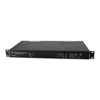
evertz 8010TM Instruction Manual (100 pages)
SDI Time Code Master With IRIG Reader
Brand:
evertz
| Category:
Network Hardware
| Size: 1.22 MB
Table of Contents
Table of Contents
7
Overview
15
How to Use this Manual
16
Definitions
16
Installation
23
Rear Panel
23
Digital Video Connections
23
Analog Monitor Video Connections
23
Linear Time Code Connections
23
Figure 2-1: 8010TM-IRIG Rear Panel
23
IRIG Code Connections
24
Tally Connections
24
Serial Port Connections
24
Table 2-1: Serial Control Pin Definitions - RS-232 DCE Configuration
24
Parallel Remote Control Connections
25
Table 2-2: Serial Control Pin Definitions - RS-422 Tributary Configuration
25
Table 2-3: Parallel Port Pin Definitions - Normal GPIO Functions
25
Power Connections
26
Mounting
26
Power Requirements
26
Selecting the Correct Mains Voltage
26
Changing the Fuse
26
Table 2-4: Parallel Port Pin Definitions - Time RCTL Mode
26
Connecting the Digital Video
27
Video Input
27
Video Output
27
Linear Time Code Connections
27
Irig Time Code Connections
27
Connecting the General Purpose Inputs and Outputs
28
Figure 2-2: Typical GPIO Circuitry
28
How to Operate the Sdi Time Code Master
33
An Overview of Key and Display Functions
33
The Setup Pushbutton Group
33
Figure 3-1: Model 8010TM-IRIG Front Panel Layout
33
The Character Window Pushbutton Group
34
The Function Button Group
34
An Overview of the SHIFT Key Functions
35
Panel Lock Key Functions
35
An Overview of the Status Indicators
35
Front Panel Display Functions
36
Front Panel Displays
36
Special Front Panel Indicators
36
An Overview of the Front Panel Programming Menu
37
Programming the Generator Modes
38
Table 3-1: Overview of the 8010TM-IRIG Main Programming Menu
38
Configuring the Generator Mode
39
Setting the Generator Time
40
Setting the Generator User Bits
41
Jam Syncing the Generator to the Reader
42
Time Date Mode
42
Entering the Time in Time Date Mode
43
Setting the Generator User Bits in Time Date Mode
43
Daylight Saving Time Support
44
Convert Mode
45
Turning the VITC Generator on
46
Selecting the Lines to Record SMPTE VITC on
46
Selecting the Lines to Record IRIG Encoded VITC on
47
Selecting the Generator Drop Frame Mode (NTSC Only)
47
Selecting the Generator Colour Frame Mode
48
Generator Parity Mode Selection
50
Configuring How the Continuous Jam Sync Mode Works When There Is no Reader Code
51
Configuring Whether the Generator will Output Local Time or UTC Time in Time/Date Modes
51
Reader Functions
52
Setting the Active Reader - Reader Assignment
52
Configuring the Selecting the Format of the IRIG Reader Time and User Bit Data3-20
52
Controlling the IRIG Reader 'Look Ahead' Compensation
53
Configuring the Selecting the Format of the VITC Reader Time and User Bit Data3-21
53
Setting the VITC Reader Line Range
54
Controlling the VITC Reader 'Look Ahead' Compensation
54
Configuring Whether the VITC Reader will Display Local Time or UTC Time in Time/Date Mode
55
Character Generator Functions
55
Selecting the Character Size
55
Selecting the Character Style
56
Selecting Whether the Frames, Fields and Symbols will be Displayed on the VCG3-24
56
Selecting and Positioning the Individual Character Inserter Windows
57
Positioning the Overall Character Display
57
Character Generator On/ off Controls
57
Special VCG Indicators
58
Turning on the SDI Video Bypass Relay
58
Programming the Engineering Setup Functions
58
Table 3-2: Overview of the 8010TM-IRIG Engineering Menu
59
Selecting the Video Type
60
Adjusting the Output Level of the LTC Generator
60
Setting the VITC Deleter Line Range
60
Selecting the Generator Date Format for Time Date Mode
61
Selecting the Colour Frame Phase
62
Setting the 25 ⇔ 30 Convert Jam Window
62
Selecting the Generator Framing Reference
63
Turning on the Daylight Saving Time Compensation
63
Configuring the General Purpose Inputs and Outputs
63
Remote Control Mode
64
Assigning the Functions of the General Purpose Inputs
65
Assigning the Functions of the General Purpose Outputs
66
Adjusting the General Purpose Output Duration
66
Setting the Time of the Event Registers
67
Configuring the Serial Port
67
Selecting the Serial Port Baud Rate
67
Testing the Serial Port
67
Testing the RAM
68
Adjusting the Front Panel Display Brightness
68
Setting the SDI Vertical Interval Blanking
68
Setting the NTSC Setup Pedestal on the Monitor Analog Output
68
Downloading New Character Fonts
68
Resetting the 8010TM-IRIG to Factory Defaults
69
Displaying the 8010TM-IRIG Software Version
69
Serial Remote Control Protocol
73
Overview
73
Connector Pin Assignment
73
Table 4-1: Serial Control Pin Definitions - RS-232 DCE Configuration
73
Data Format
74
Table 4-2: Serial Control Pin Definitions - RS-422 Tributary Configuration
74
Communications Protocol
75
Figure 4-1: Communications Protocol State Diagram
75
Message Block Format
76
Commands
77
Table 4-3: Systems Commands and Their Valid Responses
77
Table 4-4: Character Generator Commands and Their Valid Responses
78
Table 4-5: Reader Commands and Their Valid Responses
78
Data Formats
79
Time Format Block
79
Table 4-6: Generator Commands and Their Valid Responses
79
Data Format Block
80
Display Data Block
80
Command and Response Descriptions
80
System Commands
80
Video Character Inserter Commands
81
Table 4-7: VCG Window Numbers
81
Table 4-8: VCG Sizes
82
Reader Commands
83
Table 4-9: Reader Numbers
83
Table 4-10: Reader Modes
84
Generator Commands
85
Table 4-11: Generator Modes
85
Miscellaneous Commands
88
Technical Description
91
Specifications
91
Serial Digital Video Input
91
Serial Digital Video Outputs
91
Analog Monitor Video Outputs (Optional)
91
LTC Generator
91
IRIG Reader
92
General Purpose Inputs and Outputs
92
Serial Remote Control
92
Electrical
92
Physical
92
Jumpers and Switches
93
DIP Switch Functions
93
Enabling the IRIG CS-6 Compatible Broadcast Data Output
93
Configuring the Serial Port
93
Table 5-1: DIP Switch Functions
93
Upgrading the Firmware
94
Overview
94
Figure 5-1: Jumper Settings for Serial Port Configurations
94
Procedure for Firmware Upgrades
95
Viewing Firmware Revision Levels
96
Upgloading New Fonts
97
Overview
97
Procedure for Font Upgrades
97
Advertisement
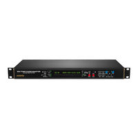
evertz 8010TM Instruction Manual (98 pages)
SDI Time Code Master
Brand:
evertz
| Category:
Media Converter
| Size: 1.4 MB
Table of Contents
Table of Contents
7
Overview
13
How to Use this Manual
14
Definitions
14
Installation
21
Rear Panel
21
Digital Video Connections
21
Analog Monitor Video Connections
21
Linear Time Code Connections
21
Figure 2-1: 8010TM Rear Panel
21
Tally Connections
22
Colour Reference Connections
22
Serial Port Connections
22
Table 2-1: Serial Control Pin Definitions - RS-232 DCE Configuration
22
Table 2-2: Serial Control Pin Definitions - RS-422 Tributary Configuration
22
Parallel Remote Control Connections
23
Power Connections
23
Table 2-3: Parallel Port Pin Definitions - Normal GPIO Functions
23
Table 2-4: Parallel Port Pin Definitions - Time RCTL Mode
23
Mounting
24
Power Requirements
24
Selecting the Correct Mains Voltage
24
Changing the Fuse
24
Connecting the Digital Video
24
Video Input
24
Video Output
25
Linear Time Code Connections
25
Connecting the General Purpose Inputs and Outputs
25
Figure 2-2: Typical GPIO Circuitry
25
How to Operate the Sdi Time Code Master
31
An Overview of Key and Display Functions
31
The Setup Pushbutton Group
31
Figure 3-1: Model 8010TM Front Panel Layout
31
The Character Window Pushbutton Group
32
The Function Button Group
32
An Overview of the SHIFT Key Functions
33
Panel Lock Key Functions
33
An Overview of the Status Indicators
33
Front Panel Display Functions
34
Front Panel Displays
34
Special Front Panel Indicators
34
An Overview of the Front Panel Programming Menu
35
Table 3-1: Overview of the 8010TM Main Programming Menu
36
Programming the Generator Modes
37
Configuring the Generator Mode
37
Setting the Generator Time
38
Setting the Generator User Bits
39
Jam Syncing the Generator to the Reader
39
Jam Syncing at Specified Time
40
Time Date Mode
41
Entering the Time in Time Date Mode
41
Setting the Generator User Bits in Time Date Mode
41
Daylight Saving Time Support
42
30 Convert Mode
43
Turning the VITC Generator on
44
Selecting the Lines to Record VITC on
45
Selecting the Generator Drop Frame Mode (NTSC Only)
45
Selecting the Generator Colour Frame Mode
46
Generator Parity Mode Selection
48
Configuring How the Continuous Jam Sync Mode Works When There Is no Reader Code
48
Configuring Whether the Generator will Output Local Time or UTC Time in Time/Date Modes
49
Reader Functions
50
Setting the Active Reader - Reader Assignment
50
Configuring the Selecting the Format of the LTC Reader Time and User Bit Data
51
Controlling the LTC Reader 'Look Ahead' Compensation
51
Configuring Whether the LTC Reader will Display Local Time or UTC Time in Time/Date Mode
52
Selecting the Format of the VITC Reader Time and User Bit Data
52
Setting the VITC Reader Line Range
52
Controlling the VITC Reader 'Look Ahead' Compensation
53
Configuring Whether the VITC Reader will Display Local Time or UTC Time in Time/Date Mode
53
Character Generator Functions
53
Selecting the Character Size
54
Selecting the Character Style
54
Selecting Whether the Frames, Fields and Symbols will be Displayed on the VCG
54
Selecting and Positioning the Individual Character Inserter Windows
55
Positioning the Overall Character Display
55
Character Generator On/ off Controls
55
Special VCG Indicators
56
Turning on the SDI Video Bypass Relay
56
Programming the Engineering Setup Functions
56
Table 3-2: Overview of the 8010TM Engineering Menu
57
Selecting the Video Type
58
Adjusting the Output Level of the LTC Generator
58
Setting the VITC Deleter Line Range
58
Selecting the Generator Date Format for Time Date Mode
59
Selecting the Colour Frame Phase
60
Setting the 25 ⇔ 30 Convert Jam Window
60
Selecting the Generator Framing Reference
60
Turning on the Daylight Saving Time Compensation
61
Configuring the General Purpose Inputs and Outputs
61
Remote Control Mode
61
Assigning the Functions of the General Purpose Inputs
62
Table 3-3: Remote Control Mode GPI I/O Mapping
62
Assigning the Functions of the General Purpose Outputs
63
Adjusting the General Purpose Output Duration
64
Setting the Time of the Event Registers
64
Configuring the Serial Port
65
Selecting the Serial Port Baud Rate
65
Testing the Serial Port
65
Testing the RAM
65
Adjusting the Front Panel Display Brightness
65
Setting the SDI Vertical Interval Blanking
66
Setting the NTSC Setup Pedestal on the Monitor Analog Output
66
Downloading New Character Fonts
66
Resetting the 8010TM to Factory Defaults
66
Displaying the 8010TM Software Version
67
Serial Remote Control Protocol
71
Overview
71
Connector Pin Assignment
71
Table 4-1: Serial Control Pin Definitions - RS-232 DCE Configuration
71
Table 4-2: Serial Control Pin Definitions - RS-422 Tributary Configuration
71
Data Format
72
Communications Protocol
72
Message Block Format
73
Figure 4-1: Communications Protocol State Diagram
73
Commands
75
Table 4-3: Systems Commands and Their Valid Responses
75
Table 4-4: Character Generator Commands and Their Valid Responses
75
Table 4-5: Reader Commands and Their Valid Responses
76
Table 4-6: Generator Commands and Their Valid Responses
76
Data Formats
77
Time Format Block
77
Display Data Block
77
Data Format Block
77
Command and Response Descriptions
78
System Commands
78
Video Character Inserter Commands
78
Table 4-7: VCG Window Numbers
78
Display Data Block
78
Table 4-8: VCG Sizes
79
Reader Commands
80
Table 4-9: Reader Numbers
80
Table 4-10: Reader Modes
81
Generator Commands
82
Table 4-11: Generator Modes
82
Miscellaneous Commands
85
Technical Description
89
Specifications
89
Serial Digital Video Input
89
Serial Digital Video Outputs
89
Analog Monitor Video Outputs (Optional)
89
Electrical
89
Physical
90
Jumpers and Switches
90
DIP Switch Functions
90
Configuring the Serial Port
90
Table 5-1: DIP Switch Functions
90
Upgrading the Firmware
91
Overview
91
Figure 5-1: Jumper Settings for Serial Port Configurations
91
Procedure for Firmware Upgrades
92
Viewing Firmware Revision Levels
93
Uploading New Fonts
94
Overview
94
Procedure for Font Upgrades
94
Calibrating the Colour Frame Detector
96
Figure 5-2: Colour Frame Calibration Test Point Location
97
Figure 5-3: PAL Colour Frame Calibration
97
Figure 5-4: NTSC Colour Frame Calibration
97
Advertisement
Related Products
evertz 8010-SIE
evertz 8010-SIE-GPSII
evertz 8084
evertz 8084AD
evertz 8085
evertz 8083XDS-AD
evertz 8950-SID
evertz 8025
evertz 8150
evertz 8950
evertz Categories
Media Converter
Network Hardware
Amplifier
Transmitter
Receiver
More evertz Manuals
Login
Sign In
OR
Sign in with Facebook
Sign in with Google
Upload manual
Upload from disk
Upload from URL