Table of Contents
Advertisement
Quick Links
© Copyright 2002 - 2014
EVERTZ MICROSYSTEMS LTD.
5288 John Lucas Drive,
Burlington, Ontario,
Canada L7L 5Z9
Phone:
905-335-3700
Sales:
sales@evertz.com
Tech Support: service@evertz.com
Web Page:
http://www.evertz.com
Version 1.5.1, January 2014
The material contained in this manual consists of information that is the property of Evertz Microsystems and is
intended solely for the use of purchasers of the 8010TM SDI Time Code Master. Evertz Microsystems expressly
prohibits the use of this manual for any purpose other than the operation of the 8010TM.
All rights reserved. No part of this publication may be reproduced without the express written permission of
Evertz Microsystems Ltd.
Microsystems.
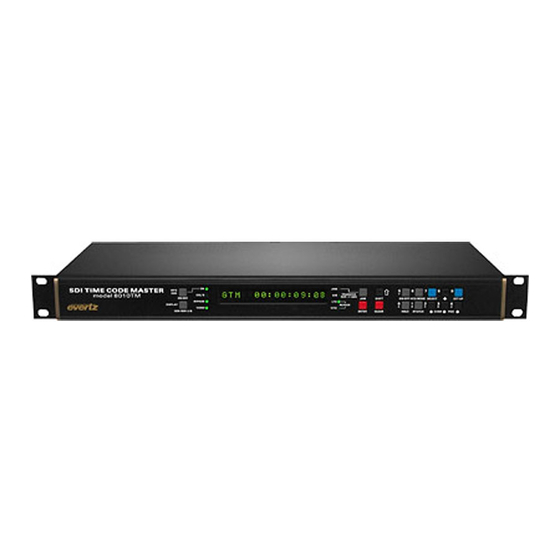
Model 8010TM
SDI Time Code Master
Instruction Manual
Fax: 905-335-3573
Fax: 905-335-7571
Copies of this manual can be ordered from your Evertz dealer or from Evertz
Advertisement
Table of Contents

Related Manuals for evertz 8010TM


Summary of Contents for evertz 8010TM
- Page 1 Version 1.5.1, January 2014 The material contained in this manual consists of information that is the property of Evertz Microsystems and is intended solely for the use of purchasers of the 8010TM SDI Time Code Master. Evertz Microsystems expressly prohibits the use of this manual for any purpose other than the operation of the 8010TM.
- Page 2 This page left intentionally blank...
- Page 3 IMPORTANT SAFETY INSTRUCTIONS The lightning flash with arrowhead symbol within an equilateral triangle is intended to alert the user to the presence of uninsulated “Dangerous voltage” within the product’s enclosure that may be of sufficient magnitude to constitute a risk of electric shock to persons. The exclamation point within an equilateral triangle is intended to alert the user to the presence of important operating and maintenance (Servicing) instructions in the literature accompanying the product.
- Page 4 WARNING Changes or Modifications not expressly approved by Evertz Microsystems Ltd. could void the user’s authority to operate the equipment. Use of unshielded plugs or cables may cause radiation interference. Properly shielded interface cables...
- Page 5 Evertz products are for informational use only and are not warranties of future performance, either expressed or implied. The only warranty offered by Evertz in relation to this product is the Evertz standard limited warranty, stated in the sales contract or order confirmation form.
- Page 6 Model 8010TM SDI Time Code Master Manual This page left intentionally blank Revision 1.5.1...
-
Page 7: Table Of Contents
Model 8010TM SDI Time Code Master Manual TABLE OF CONTENTS OVERVIEW ........................... 1-1 1.1. HOW TO USE THIS MANUAL ..................1-2 1.2. DEFINITIONS ....................... 1-2 INSTALLATION ........................2-1 2.1. REAR PANEL ....................... 2-1 2.1.1. Digital Video Connections ................... 2-1 2.1.2. Analog Monitor Video Connections..............2-1 2.1.3. - Page 8 Model 8010TM SDI Time Code Master Manual 3.4.1. Configuring the Generator Mode ................3-7 3.4.2. Setting the Generator Time..................3-8 3.4.3. Setting the Generator User Bits ................3-9 3.4.4. Jam Syncing the Generator to the Reader............3-9 3.4.4.1. Jam Syncing At Specified Time............3-10 3.4.5.
- Page 9 3.7.13. Setting the NTSC Setup Pedestal on the Monitor Analog Output......................3-36 3.7.14. Downloading New Character Fonts ..............3-36 3.7.15. Resetting the 8010TM to Factory Defaults ............3-36 3.7.16. Displaying the 8010TM Software Version ............3-37 SERIAL REMOTE CONTROL PROTOCOL ................4-1 4.1.
- Page 10 Table 2-3: Parallel Port Pin Definitions – Normal GPIO Functions .............2-3 Table 2-4: Parallel Port Pin Definitions – Time RCTL Mode ...............2-3 Table 3-1: Overview of the 8010TM Main Programming Menu ..............3-6 Table 3-2: Overview of the 8010TM Engineering Menu ................3-27 Table 3-3: Remote Control Mode GPI I/O Mapping .................3-32...
- Page 11 Model 8010TM SDI Time Code Master Manual CHAPTER 1: OVERVIEW TABLE OF CONTENTS OVERVIEW ........................... 1-1 1.1. HOW TO USE THIS MANUAL ..................1-2 1.2. DEFINITIONS ....................... 1-2 Revision 1.5.1...
- Page 12 Model 8010TM SDI Time Code Master Manual This page left intentionally blank Revision 1.5.1...
-
Page 13: Overview
Two jam sync modes allow the 8010TM generator to be slaved to incoming LTC or D-VITC. In the continuous jam sync mode, the generator is slaved to the reader, and will follow code discontinuities of the reader. -
Page 14: How To Use This Manual
Model 8010TM SDI Time Code Master Manual • GPI Remote Control mode allows user to pass remote control contact closure information in VITC user bits • Recalculates and inserts EDH on the SDI output • Serial Remote Control of most functions - Broadcasts reader data or sends it on request. - Page 15 Model 8010TM SDI Time Code Master Manual BYTE: A complete set of quantized levels containing all the bits. Bytes consisting of 8 to 10 bits per sample are typical in digital video systems. CABLE EQUALIZATION: The process of altering the frequency response of a video amplifier to compensate for high frequency losses in coaxial cable.
- Page 16 4:2:2 sampled standard definition serial digital television signals as specified in SMPTE 259M. SMPTE: Society of Motion Picture and Television Engineers. SMPTE is a professional organization that recommends standards for the film and television industries. Evertz is a sustaining member of this engineering organization. Page 1-4 OVERVIEW Revision 1.5.1...
- Page 17 Model 8010TM SDI Time Code Master Manual SMPTE 125M: The SMPTE standard for bit parallel digital interface for component video signals. SMPTE 125M defines the parameters required to generate and distribute component video signals on a parallel interface for 525 line video systems.
- Page 18 Model 8010TM SDI Time Code Master Manual This page left intentionally blank Page 1-6 OVERVIEW Revision 1.5.1...
- Page 19 Model 8010TM SDI Time Code Master Manual CHAPTER 2: INSTALLATION TABLE OF CONTENTS INSTALLATION ........................2-1 2.1. REAR PANEL ....................... 2-1 2.1.1. Digital Video Connections ................... 2-1 2.1.2. Analog Monitor Video Connections..............2-1 2.1.3. Linear Time Code Connections ................2-1 2.1.4.
- Page 20 Model 8010TM SDI Time Code Master Manual This page left intentionally blank Revision 1.5.1...
-
Page 21: Installation
REAR PANEL Figure 2-1: 8010TM Rear Panel The following sections describe the purpose of the rear panel connectors of the 8010TM. Sections 2.1.1 to 2.1.8 describe the specific signals that should be connected to the 8010TM. 2.1.1. Digital Video Connections... -
Page 22: Tally Connections
See section 5.2.2 for the information on configuring the port for various applications. On the 8010TM this port is configured at the factory for a ‘straight through RS-232 connection to a PC COM port. In this configuration it can be used for uploading firmware to the unit or serial remote control. -
Page 23: Parallel Remote Control Connections
Table 2-4: Parallel Port Pin Definitions – Time RCTL Mode 2.1.8. Power Connections LINE: The 8010TM has a universal power supply operating on 100 to 240v, 60 or 50 Hz AC. Dual supply versions have an identical redundant supply. INSTALLATION Page 2-3 Revision 1.5.1... -
Page 24: Mounting
2.3.1. Selecting the Correct Mains Voltage Power requirements are 100 to 240 volts AC at 50 or 60 Hz. The 8010TM has a universal power supply that automatically senses the input voltage. Power should be applied by connecting a 3-wire grounding type power supply cord to the power entry module on the rear panel. -
Page 25: Video Output
LINEAR TIME CODE CONNECTIONS The LTC reader input provides a means of bringing linear time code into the 8010TM. Pin 1 of the XLR is ground, and pins 2 and 3 provide a balanced output. When using an unbalanced input to the reader, the signal should be applied to pin 3 of the LTC reader input connector. - Page 26 Model 8010TM SDI Time Code Master Manual This page left intentionally blank Page 2-6 INSTALLATION Revision 1.5.1...
- Page 27 Model 8010TM SDI Time Code Master Manual CHAPTER 3: OPERATION TABLE OF CONTENTS HOW TO OPERATE THE SDI TIME CODE MASTER............. 3-1 3.1. AN OVERVIEW OF KEY AND DISPLAY FUNCTIONS ..........3-1 3.1.1. The Setup Pushbutton Group ................3-1 3.1.2. The Character Window Pushbutton Group............3-2 3.1.3.
- Page 28 3.7.13. Setting the NTSC Setup Pedestal on the Monitor Analog Output ......................3-36 3.7.14. Downloading New Character Fonts ..............3-36 3.7.15. Resetting the 8010TM to Factory Defaults ............3-36 3.7.16. Displaying the 8010TM Software Version ............3-37 Figures Figure 3-1: Model 8010TM Front Panel Layout ..................3-1...
- Page 29 Model 8010TM SDI Time Code Master Manual Tables Table 3-1: Overview of the 8010TM Main Programming Menu ..............3-6 Table 3-2: Overview of the 8010TM Engineering Menu ................3-27 Table 3-3: Remote Control Mode GPI I/O Mapping ................. 3-32 Revision 1.5.1...
- Page 30 Model 8010TM SDI Time Code Master Manual This page left intentionally blank Revision 1.5.1...
-
Page 31: How To Operate The Sdi Time Code Master
(Throughout this manual SHIFT + indicates that you should hold down the SHIFT key while pressing the second key.) A front panel programming menu provides a quick and simple method of configuring the 8010TM for your application. Sections 3.2 to 3.7.16 give detailed information on the specific operations required to control the 8010TM. -
Page 32: The Character Window Pushbutton Group
Press the WINDOW key again to select the LTC reader user bits VCG window. Press the WINDOW key again to select the next window and so on. The 8010TM returns to the normal VCG display mode after the last window has been selected. -
Page 33: An Overview Of The Shift Key Functions
Panel lock off 3.1.6. An Overview of the Status Indicators There are 8 status indicators located on the front panel that show operational status of the 8010TM at a glance. VITC GEN: Indicates that the VITC keyer is enabled. -
Page 34: Front Panel Display Functions
Drop Frame (NTSC) Period (.) The following special indicators are used between the hours and minutes digits of the front panel time display when the 8010TM is in Time/Date mode generating local time and the time being adjusted for Daylight Saving Time. -
Page 35: An Overview Of The Front Panel Programming Menu
Setup key group (SELECT, SETUP, ) are used to cycle through the various items on the programming menu. The 8010TM menu system consists of a main menu with two or more choices for each menu item. The sub-menu items are shown in lower case to allow them to be easily distinguished from the main level items. -
Page 36: Table 3-1: Overview Of The 8010Tm Main Programming Menu
Configures the generator colour frame mode GEN LTC PARITY Configures the parity of the LTC generator Configures the action when input code is missing and the 8010TM is in GEN NO CODE JAM continuous JAM sync mode GEN TM ZONE ADJ... -
Page 37: Programming The Generator Modes
When the Gmode time rtime 8010TM is not in the Jam sync mode, the generator Time bits contain time information entered from the front panel. When the 8010TM is in... -
Page 38: Setting The Generator Time
Model 8010TM SDI Time Code Master Manual Gmode time rctl sets the 8010TM into a user bit remote control mode. In this mode six of the input pins on the parallel remote control port are used to control the setting of the six remote control user bits. When the 7721GPI-D GPI decoder module reads the VITC, these encoded user bits directly control six contact closure outputs. -
Page 39: Setting The Generator User Bits
3.4.7. When the 8010TM is in the time rtime or time rub modes, the user bits are being transferred from the active reader. When the 8010TM is in the time rctl mode, the user bits are determined by the state of the parallel remote control inputs. -
Page 40: Jam Syncing At Specified Time
Jam sync mode should be used when you need to generate D-VITC that follows an LTC source time code. In this mode the 8010TM will function as an LTC to D-VITC translator. Jam sync mode should be also used when dubbing longitudinal time code from one tape to another, as the quality of the time code signal deteriorates with each generation, and will become unusable after the third generation. -
Page 41: Time Date Mode
3.4.5. Time Date Mode In time date mode the 8010TM puts date and time zone information into the user bits. It is capable of displaying time/date information in either the Universal Coordinated Time (UTC) or the local time that has been adjusted with the appropriate time zone offset from UTC. -
Page 42: Daylight Saving Time Support
UTC. If you want to re-enter this time zone offset, press ENTER. To change the whole hour offset press the or keys. To change the partial hour offset press the or keys. The 8010TM will only allow valid time zone offsets to be selected. If daylight saving time is observed in your area, then you should enter the time zone offset for standard time. -
Page 43: 30 Convert Mode
3.4.9. 25 30 Convert Mode The 8010TM can be operated in a 25 30 time code conversion mode. (Often referred to as EBU and SMPTE time code respectively) This feature would normally be used to convert time code in standard conversion applications. -
Page 44: Turning The Vitc Generator On
Model 8010TM SDI Time Code Master Manual The JAM WINDOW parameter has been added to the Engineering Setup menu. This parameter is used to ignore the natural differences between 30 Fps and 25 Fps frame numbers within the second. The frame counting rates of 25 Fps and 30 Fps along with the natural difference between the video rates of 29.97 and 30 Fps (taking into account the dropped frames) produce an acceptable difference... -
Page 45: Selecting The Lines To Record Vitc On
(0, 1) at the start of each minute, except minutes 0, 10, 20, 30, 40, and 50. A drop frame flag bit is set in the code when the drop frame format is used. When the 8010TM is operating in the NTSC (525 line) video standard, the generator may be programmed to operate in either the drop frame or non drop frame mode. -
Page 46: Selecting The Generator Colour Frame Mode
3.4.13. Selecting the Generator Colour Frame Mode In most applications the 8010TM will be gen-locked to the program video. It is also necessary to supply an external colour reference if you desire to apply colour frame synchronization to the generated time code. - Page 47 Model 8010TM SDI Time Code Master Manual When the video standard is 625: When the video standard is 625 the 8010TM must get its colour frame information from the External Colour frame reference input. The COL’R REF LED will be on.
-
Page 48: Generator Parity Mode Selection
Model 8010TM SDI Time Code Master Manual 3.4.14. Generator Parity Mode Selection The purpose of the phase correction parity bit (LTC bit 27 in NTSC, 59 in PAL) is to compensate for phase reversals in the LTC bi-phase mark modulation that could occur when code inserts are performed. -
Page 49: Configuring Whether The Generator Will Output Local Time Or Utc Time In Time/Date Modes
Model 8010TM SDI Time Code Master Manual 3.4.16. Configuring Whether the Generator will Output Local Time or UTC Time in Time/Date Modes GEN TIME ZONE ADJ When the GEN MODE is set to TIME DATE, the generator internal time Gtm zone adj utc... -
Page 50: Reader Functions
Model 8010TM SDI Time Code Master Manual 3.5. READER FUNCTIONS 3.5.1. Setting the Active Reader – Reader Assignment RDR ASSIGNMENT The RDR ASSIGNMENT menu is used to select whether the LTC or VITC reader will be used in the momentary and continuous Jam Sync Rass (ltc) vitc modes. -
Page 51: Configuring The Selecting The Format Of The Ltc Reader Time And User Bit Data
Model 8010TM SDI Time Code Master Manual 3.5.2. Configuring the Selecting the Format of the LTC Reader Time and User Bit Data LTC RDR MODE The LTC RDR MODE menu item is used to select the type of LR mode time data... -
Page 52: Configuring Whether The Ltc Reader Will Display Local Time Or Utc Time In Time/Date Mode
The local time will also be adjusted by the daylight savings time adjustment if daylight savings time is in effect. See section 3.4.8 for a discussion of daylight saving time features of the 8010TM. Select Ltm zone adj utc to configure the reader to output its time as UTC. -
Page 53: Controlling The Vitc Reader 'Look Ahead' Compensation
3.6. CHARACTER GENERATOR FUNCTIONS The 8010TM has six independently positionable character windows to display the generator and LTC and VITC reader time and user bits. The four arrow keys (, , , ) control the position of all the windows. The CHAR GEN ON/OFF key selects whether the video character generator (VCG) keyer is on or off. -
Page 54: Selecting The Character Size
Model 8010TM SDI Time Code Master Manual 3.6.1. Selecting the Character Size CHAR SIZE The CHAR SIZE menu item is used to select one of three sizes for the Char tiny character generator’s display. Char small The Char tiny character size occupies 8 lines per field for each Char large character row. -
Page 55: Selecting And Positioning The Individual Character Inserter Windows
Source ID window on or off and the arrow keys to move it to the desired location. Press the WINDOW key again to select the next window and the arrow keys to move it to the desired location and so on. The 8010TM returns to the normal VCG display mode after the last window has been selected. -
Page 56: Special Vcg Indicators
This allows the user to Bypass mode off manually put the 8010TM in Bypass mode. In this mode, the input Bypass mode on video is directly connected to the output, and the encoder will no longer be active. -
Page 57: Table 3-2: Overview Of The 8010Tm Engineering Menu
FACTORY RESET Resets the encoder to its Factory default condition Table 3-2: Overview of the 8010TM Engineering Menu Table 3-2 shows the items in the main level of the engineering menu tree. Sections 3.7.1 to 3.7.16 provide detailed descriptions of each of the sub-menus. The tables in these sections are arranged in an indented structure to indicate the path taken to reach the control. -
Page 58: Selecting The Video Type
Model 8010TM SDI Time Code Master Manual 3.7.1. Selecting the Video Type VIDEO TYPE The VIDEO TYPE menu item is used to program the 8010TM for the Video auto (525) digital video format. Video 525 When you select auto the 8010TM will auto detect the line rate and Video 625 automatically reconfigure itself. -
Page 59: Selecting The Generator Date Format For Time Date Mode
Model 8010TM SDI Time Code Master Manual 3.7.4. Selecting the Generator Date Format for Time Date Mode GEN DATE FORMAT The GEN DATE FORMAT menu item is used to set the encoding Gen date yymmdd format when date information is being placed into the user bits. -
Page 60: Selecting The Colour Frame Phase
The REFERENCE MODE menu item is used to set whether the internal Ref auto timing of the 8010TM will be locked to the input video or the External Colour Reference input. The updating of the generator clock, character Ref input... -
Page 61: Turning On The Daylight Saving Time Compensation
8010TM functions. There are also two open collector outputs that can be assigned to a variety of functions. The pinout of the D connector when the 8010TM is not in the time rctl mode is shown in Table 2-3. -
Page 62: Assigning The Functions Of The General Purpose Inputs
Please Note: Some early versions of the 7721GPI-D only support outputs 1 to 5. These units can be upgraded to support all six outputs. Contact Evertz customer service for information on how to upgrade these units. 3.7.9.2. Assigning the Functions of the General Purpose Inputs When the GEN MODE is NOT set to time rctl there are four dedicated remote control input pins and two user programmable inputs. -
Page 63: Assigning The Functions Of The General Purpose Outputs
Model 8010TM SDI Time Code Master Manual GPI1 ASSIGNMENT The following descriptions indicate how the GPI will function with each setting. Gpi1 = ltc active Gpi1 = vitc active Ltc active Provides an alternate method of selecting the LTC Gpi1 = gen hold reader as the active reader. -
Page 64: Adjusting The General Purpose Output Duration
Model 8010TM SDI Time Code Master Manual GPO1 ASSIGNMENT The following descriptions indicate how the GPO will function with each setting. Gpo1 = rdr event Gpo1 = gen event Rdr event The output will activate for the GPO Duration when the... -
Page 65: Configuring The Serial Port
3.7.10.2. Testing the Serial Port SERIAL TEST The SERIAL TEST menu item is used to turn on a serial port test message. When the serial test is on, the 8010TM outputs a message Serial test off similar to: Serial test on EVERTZ DTCG 8010TM SOFTWARE VERSION DG86D1.M... -
Page 66: Setting The Sdi Vertical Interval Blanking
5.4. 3.7.15. Resetting the 8010TM to Factory Defaults FACTORY RESET The FACTORY RESET menu item is used to return the 8010TM to its factory defaults. When you press the or keys, the display shows Shift+sel=reset Shift+sel=reset. When you press SHIFT + SELECT the 8010TM will... -
Page 67: Displaying The 8010Tm Software Version
Model 8010TM SDI Time Code Master Manual 3.7.16. Displaying the 8010TM Software Version SOFTWARE VERSION The SOFTWARE VERSION menu item is used to display the 8010TM’s software version. When you press the or keys, the display shows DG86D1.M R021204 the software version which will look similar to the following: DG86D1.M R021204... - Page 68 Model 8010TM SDI Time Code Master Manual This page left intentionally blank Page 3-38 OPERATION Revision 1.5.1...
- Page 69 Model 8010TM SDI Time Code Master Manual CHAPTER 4: SERIAL PROTOCOL TABLE OF CONTENTS SERIAL REMOTE CONTROL PROTOCOL ................4-1 4.1. OVERVIEW........................4-1 4.1.1. Connector Pin Assignment.................. 4-1 4.1.2. Data Format ....................... 4-2 4.2. COMMUNICATIONS PROTOCOL ................. 4-2 4.3. MESSAGE BLOCK FORMAT ..................4-3 4.4.
- Page 70 Model 8010TM SDI Time Code Master Manual This page left intentionally blank Revision 1.5.1...
-
Page 71: Serial Remote Control Protocol
Model 8010TM SDI Time Code Master Manual SERIAL REMOTE CONTROL PROTOCOL 4.1. OVERVIEW • Two wire interface using RS-232C levels or alternate four wire communications channel using RS-422 levels. • Data transmitted asynchronously, bit serial, word serial with data exchange between the devices being digital. -
Page 72: Data Format
COMMUNICATIONS PROTOCOL The Controller shall be denoted as the normal sender of a command (usually a computer). The Device shall be denoted as the normal sender of a Response (the 8010TM). All command values, arguments and data values shown in this document are expressed in hexadecimal format unless otherwise noted. -
Page 73: Message Block Format
T(NAK) Figure 4-1: Communications Protocol State Diagram The communications protocol is described in Figure 4-1. The Evertz unit (Device) immediately enters the select state upon power-up and remains there unless directed by an Enter Broadcast Cmd (02 hex) to the broadcast communications state. The diagram shows the various states of the device. The designation R( ) indicates the data received from the controller, while the designation T( ) indicates the data transmitted by the Device. - Page 74 Model 8010TM SDI Time Code Master Manual Start of message character (02 hex) BYTE COUNT Count of command message not including the STX, BYTE COUNT or CHECKSUM. MESSAGE Variable length command message. CHECKSUM The two's complement of the one byte sum of the MESSAGE and the BYTE COUNT.
-
Page 75: Commands
Model 8010TM SDI Time Code Master Manual 4.4. COMMANDS Command from Controlling Device Return to Controlling Device DATA DATA DESCRIPTION ECHO NAME BYTES BYTES BYTES Sense Current Mode Current Mode Enter Select Mode Enter Broadcast Mode Enter Remote Ctl Panel Mode... -
Page 76: Table 4-5: Reader Commands And Their Valid Responses
Model 8010TM SDI Time Code Master Manual Command from Controlling Device Return to Controlling Device DATA DATA DESCRIPTION ECHO NAME BYTES BYTES BYTES Select Reader Assignment Select Reader Mode Select Reader Display Define Broadcast Mode Select Reader Time Zone Adjustment... -
Page 77: Data Formats
Model 8010TM SDI Time Code Master Manual 4.5. DATA FORMATS Time Format Block 4.5.1. 10 Frm 1 Frm 10 Sec 1 Sec 10 Min 1 Min 10 Hr 1 Hr Flags The Flags byte is a bitmapped byte of the time code flag bits as follows:... -
Page 78: Command And Response Descriptions
Model 8010TM SDI Time Code Master Manual 4.6. COMMAND AND RESPONSE DESCRIPTIONS 4.6.1. System Commands Sense Current Mode Returns 2 bytes as follows 01 = Select 02 = Broadcast 03 = RCU Enter Select Mode Enter Broadcast Mode Sense PROM Version... -
Page 79: Table 4-8: Vcg Sizes
Model 8010TM SDI Time Code Master Manual Sense Char Gen Size Returns 1 byte as defined below. Select Char Gen Size 1 byte Selects the size of the VCG Character Font 00 = Tiny 01 = Small 02 = Large... -
Page 80: Reader Commands
Model 8010TM SDI Time Code Master Manual Sense Char Gen Style Returns 1 byte as defined below. Select Char Gen Style 1 byte Selects the Style of the VCG windows. 00 = White 01 = White on Black 02 = Black... -
Page 81: Table 4-10: Reader Modes
Model 8010TM SDI Time Code Master Manual Sense RDR Assignment Returns 1 byte as defined below Select RDR Assignment 1 byte Selects the Reader assignment 01 = LTC 02 = VITC 03 = Auto LTC/VITC –equal priority 04 = Auto LTC/VITC –LTC priority 05 = Auto LTC/VITC –VITC priority... -
Page 82: Generator Commands
Model 8010TM SDI Time Code Master Manual Sense Reader 1 byte Returns Reader data as defined by the following byte: VTRU LTRU VTRT LTRT Each bit represents a variable length block of data that is requested. Time and data are formatted according to the Select RDR Mode command above. - Page 83 Model 8010TM SDI Time Code Master Manual Sense VITC Generator Lines Returns 2 bytes as defined below. Preset VITC Generator Lines 2 bytes Presets the line numbers of the VITC generator To generate VITC on only one line set Line 1 and Line 2 equal. Line numbers are packed BCD format.
- Page 84 Model 8010TM SDI Time Code Master Manual Sense Generator Run/Hold Returns 1 byte as defined below. Select Generator Run/Hold 1 byte Turns the Generator Hold On and Off. 00 = Generator Hold 01 = Generator Run Sense Generator Jam Sync Mode Returns 1 byte as defined below.
-
Page 85: Miscellaneous Commands
Model 8010TM SDI Time Code Master Manual Sense Generator 1 byte Defines a block of data that will be sent in response to a Sense Generator command. Each bit represents a 4 byte block of which is requested. Time and user bit formats are determined by the Select Generator Mode command. - Page 86 Model 8010TM SDI Time Code Master Manual The four bytes of time data is in BCD format as shown below. 10 Fr 1 Fr 10 Sec 1 sec 10 Min 1 Min 10 Hr Page 4-16 SERIAL PROTOCOL Revision 1.5.1...
- Page 87 Model 8010TM SDI Time Code Master Manual CHAPTER 5: TECHNICAL DESCRIPTION TABLE OF CONTENTS TECHNICAL DESCRIPTION ....................5-1 5.1. SPECIFICATIONS ......................5-1 5.1.1. Serial Digital Video Input..................5-1 5.1.2. Serial Digital Video Outputs ................5-1 5.1.3. Analog Monitor Video Outputs (optional) ............. 5-1 5.1.4.
- Page 88 Model 8010TM SDI Time Code Master Manual This page left intentionally blank Revision 1.5.1...
-
Page 89: Technical Description
Model 8010TM SDI Time Code Master Manual TECHNICAL DESCRIPTION 5.1. SPECIFICATIONS 5.1.1. Serial Digital Video Input Standards: SMPTE 259M (270 Mb/s) Connector: 1 BNC input per IEC 169-8 Equalization: Automatic 200m @ 270 Mb/s with Belden 8281 or equivalent cable... -
Page 90: Physical
Model 8010TM SDI Time Code Master Manual 5.1.5. Physical Single Power Supply Version: Dimensions: 19” W x 1.75” H x 7.75” D (483mm W x 45mm H x 196mm D) Weight: 7 lbs. (3.2 Kg) Dual Power Supply Version: Dimensions: 19”... -
Page 91: Upgrading The Firmware
Model 8010TM SDI Time Code Master Manual RS-422 RS-422 RS-232 DCE RS-232 DTE TRIBUTARY CONTROLLER Figure 5-1: Jumper Settings for Serial Port Configurations 5.3. UPGRADING THE FIRMWARE 5.3.1. Overview The SDI Time Code Master contains firmware in a FLASH ROM device. From time to time firmware updates may be provided to add additional features to the unit. -
Page 92: Procedure For Firmware Upgrades
Model 8010TM SDI Time Code Master Manual 5.3.2. Procedure for Firmware Upgrades 1. If you have changed the Serial port wiring from the factory default you will need to remove the top cover and set the jumpers on jumper block J9 to the RS-232 DCE settings. -
Page 93: Viewing Firmware Revision Levels
Model 8010TM SDI Time Code Master Manual 8. The following is a list of possible reasons for failed communications: • Defective Serial cable. • Wrong communications port selected in the terminal program. • Improper port settings in the terminal program. (Refer to step 3 for settings). -
Page 94: Uploading New Fonts
This is the actual firmware revision for the SDI Time Code Master. If the first character is R021122 a ‘U’ instead of an ‘R’ then the SDI Time Code Master contains unreleased beta firmware. (Evertz does not ship unreleased SDI Time Code Master firmware, except where customers have requested special features.) 5.4. - Page 95 Model 8010TM SDI Time Code Master Manual 7. The front panel will display the word PROGRAMMER-19200. You should also see a menu appear in the terminal window on the PC. For example: ***** Unknown Main Flash Memory Chip ***** *****...
-
Page 96: Calibrating The Colour Frame Detector
CALIBRATING THE COLOUR FRAME DETECTOR Calibration of the colour frame detector is accomplished in software by adjusting digital potentiometer (U23). Separate calibration values are maintained in the 8010TM’s nonvolatile memory for PAL and NTSC. The colour frame circuitry is calibrated at the factory and should not require any field calibration. -
Page 97: Figure 5-2: Colour Frame Calibration Test Point Location
NOVPOT to 11. The COL’R LED should be On. Repeat the procedure for the other video standard as required. Set DIP switch #8 to the Off (open) position to return the 8010TM to its normal operating mode. TECHNICAL DESCRIPTION Page 5-9... - Page 98 Model 8010TM SDI Time Code Master Manual This page left intentionally blank Page 5-10 TECHNICAL DESCRIPTION Revision 1.5.1...
Need help?
Do you have a question about the 8010TM and is the answer not in the manual?
Questions and answers