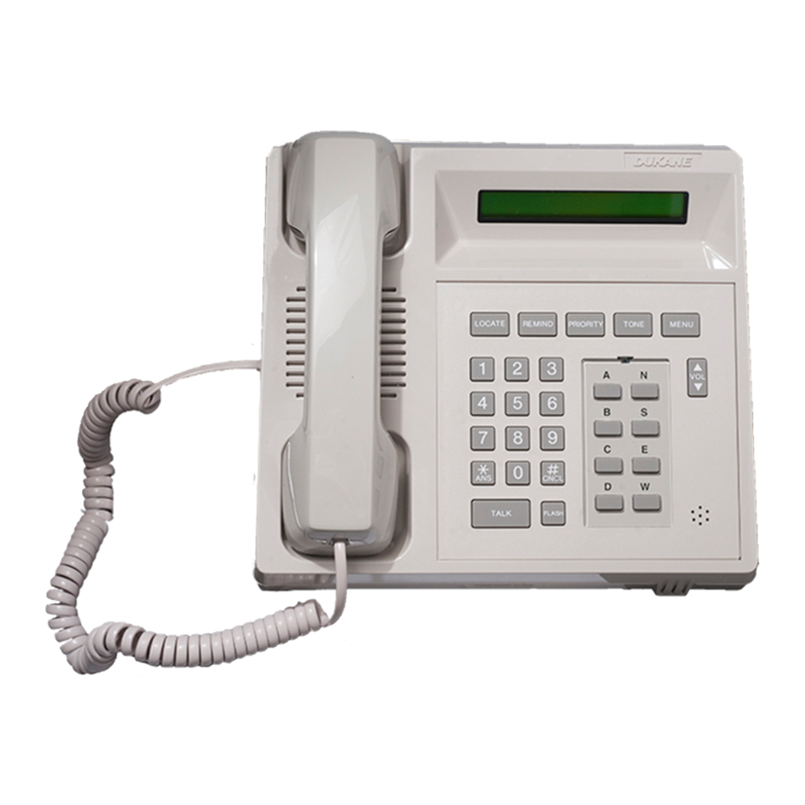
Sign In
Upload
Manuals
Brands
Dukane Manuals
IP Phone
4A3610B
Dukane 4A3610B Manuals
Manuals and User Guides for Dukane 4A3610B. We have
1
Dukane 4A3610B manual available for free PDF download: Operation Manual
Dukane 4A3610B Operation Manual (148 pages)
ProCare 6000
Brand:
Dukane
| Category:
IP Phone
| Size: 3.81 MB
Table of Contents
Copyright Notice
3
Table of Contents
7
Introduction
19
Related Documentation
19
Technical Support
20
Section 1-General Information
19
Base Master Features
20
General Description
20
Figure 1-1: Model 4A3610B Base Master
20
Tones
21
Call Tone and Recall Tone
21
Confirmation (OK) Tone
21
Error (ERR) Tone
22
Busy Tone
22
Reset Tone
22
Fail Tone
22
Tone Level
22
Base Master Layout
23
Display Window
23
Handset
23
Key Pad
23
Answer (*ANS) Key
23
Cancel (#CNCL) Key
24
TALK Button
24
FLASH Button
24
Microphone
24
Volume Control Button
24
Function Buttons
25
Eight Configurable Alpha Buttons
25
Figure 1-2: Idle State
26
Figure 1-3: Time State
26
Idle/Time Display
26
Flashing Display Codes
27
Figure 1-4: Base Master with Model 438-815A Installed
28
Optional Four-Line Display
28
Following Instructions
29
Default Settings
29
Direct Access Key Sequence
29
Key Pad Instructions
29
Display Prompts and Messages
30
Auto Scrolling
30
Base Master Care
30
Section 2-Base Master Operations
31
Figure 2-1: Pending Call Display with One Call
31
Introduction
31
Video Display Interactions
31
Pending Call Display
31
Answering a Call
32
Automatically Answering a Pending Call (*ANS)
32
Figure 2-2: Pending Call Display with Three Calls
32
Figure 2-3: Automatically Answering a Call
32
Selectively Answering a Pending Call (VOL, *ANS)
33
Figure 2-4: Automatically Answering the Last Call
33
Figure 2-5: Selectively Answering a Call
33
Placing a Call
34
Placing a Call Using the Key Pad and Alpha Keys
34
Figure 2-6: Station Number Appearing in the Connect Display
34
Placing a Call Using Speed Dial
35
Placing a Call Using Auto-Dialing
35
Assigning Staff to a Station While Connected to a Call
36
Assigning Primary Staff (MENU, 3, 1)
36
Figure 2-7: Old Primary Staff Assignment
36
Figure 2-8: New Primary Staff Assignment
36
Assigning Alternate Staff (MENU, 3, 2)
37
Figure 2-9: Old Alternate Staff Assignment
37
Figure 2-10: New Alternate Staff Assignment
38
Figure 2-11: Message Display Prompt
39
Paging Primary Staff (MENU, 5, 1)
39
Paging Alternate Staff (MENU, 5, 2)
40
Figure 2-12: Paging Staff by ID Number
41
Figure 2-13: Message Display Prompt
41
Paging Staff by Staff ID Number (MENU, 5, 3)
41
Figure 2-14: Pager Number Display
42
Figure 2-15: Message Display Prompt
42
Paging Staff by Pager ID Number (MENU, 5, 4)
42
Pocket Pager Messages
43
Sending a Pocket Page While Connected to a Call
38
Chart 2-1: Pocket Pager Messages
43
Using the LOCATE Button
45
Viewing Staff Locations
45
Figure 2-16: Staff Location Display
45
Using the REMIND Button
46
Placing a Call on Reminder
46
Figure 2-17: Idle Display Showing an Amber Reminder (RA)
46
Canceling a Reminder
47
Reminder Recalls
47
Automatically Answering a Reminder Recall
47
Figure 2-18: Reminder Recall Display
47
Viewing and Connecting to Set Reminders
48
Figure 2-19: Display Showing Level and Number of Reminders Set
48
Using the PRIORITY Button
49
Assigning Station Call Priorities
49
Assigning Station Auxiliaries or Station Prime Auxiliaries
50
Assigning Team Pagers to a Station
51
Using the TONE Button
52
Silencing Pending Call Tones
52
Silencing Error Tones
52
Figure 2-20: Pending Call Tone Silence Indiction
52
Figure 2-21: Error Indication
52
The "Ownerout" Message
53
Figure 2-22: Ownerout Display
53
Section 3-Menu Operations
55
Introduction
55
Using the Base Master Menu
55
Accessing Menu Selections
55
If an Error Tone Sounds When Accessing Menu Selections
55
Auto-Dialing (MENU, 1)
56
Chart 3-1: Preprogrammed Auto-Dial Numbers
56
Figure 3-1: Auto-Dial Display Showing Station 1161 Dialed Automatically
56
Figure 3-2: on Duty Idle Display
57
Figure 3-3: off Duty Idle Display
57
Placing the Master On/Off Duty (MENU, 2)
57
Assigning Base Masters, Staff, and Stations (MENU, 3)
58
Capturing Base Master Coverage (MENU, 3, 1, 1)
58
Figure 3-4: Capture Base Master Display
58
Figure 3-5: Scanning Captured or Shared Base Masters
58
Figure 3-6: Capturing Base Master's Display Showing Captured Base Masters
59
Figure 3-7: Captured Base Master's Display
59
Sharing Base Master Coverage (MENU, 3, 1, 2)
60
Figure 3-8: Share Base Master Display
60
Figure 3-9: Scanning Captured or Shared Base Masters
60
Figure 3-10: Display Showing a Shared Base Master
61
Releasing Captured and Shared Base Masters (MENU, 3, 1, 3)
62
Figure 3-11: Releasing Captured or Shared Base Masters
62
Scanning Captured and Shared Base Masters (MENU, 3, 1, 4)
63
Figure 3-12: Scanning Captured or Shared Base Masters
63
Assigning Primary Staff to Stations (MENU, 3, 2, 1)
64
Figure 3-13: Assigning Primary Staff to a Station
64
Figure 3-14: New Primary Staff Display
64
Assigning Alternate Staff to Stations (MENU, 3, 2, 2)
65
Figure 3-15: Assigning Alternate Staff to a Station
65
Creating Staff Ids (MENU, 3, 2, 3)
66
Figure 3-16: New Alternate Staff Display
66
Swinging a Station to Your Base Master (MENU, 3, 3, 1)
67
Figure 3-17: Creating Staff Ids
67
Figure 3-18: Assigning Swing Stations to a Base Master
67
Swinging a Station to a Duty Area (MENU, 3, 3, 2)
68
Figure 3-19: Assigning Swing Stations to a Duty Area
69
Chart 3-2: Designated Swing Stations
69
Performing Audio Page Functions (MENU, 4)
70
Performing a Hallway Page (MENU, 4, 1)
70
Performing an All Page (MENU, 4, 2)
71
Performing a Base Master Page (MENU, 4, 3)
72
Performing an Area Page (MENU, 4, 4)
73
Performing Pocket Page Functions (MENU, 5)
74
Paging Primary Staff (MENU, 5, 1)
74
Figure 3-20: Accessing Primary or Alternate Staff Assigned to a Station
74
Figure 3-21: Paging Primary or Alternate Staff
74
Paging Alternate Staff (MENU, 5, 2)
75
Paging Staff by Staff ID Number (MENU, 5, 3)
76
Figure 3-22: Paging Staff by ID Number
76
Figure 3-23: Transmitting a Message to Staff by Staff ID
76
Paging Staff by Pager Number (MENU, 5, 4)
77
Figure 3-24: Paging Staff by Pager Number
77
Figure 3-25: Transmitting a Message to Staff by Pager Number
77
Assigning a Pager Number to a Staff Member (MENU, 5, 5)
78
Figure 3-26: Assigning a Pager Number to a Staff Member
78
Assigning a Charge Pager Number (MENU, 5, 6)
79
Figure 3-27: Assigning a Charge Pager
79
Creating Pager Numbers (MENU, 5, 7)
80
Figure 3-28: Creating Pager Numbers
80
Changing Tone, Date, and Time Settings (MENU, 6)
81
Setting the Tone Level (MENU, 6, 1)
81
Figure 3-29: Setting the Tone Level Display
81
Setting the Date and Time (MENU, 6, 2)
82
Figure 3-30: Setting the Date Display
82
Accessing Testing and Programming Functions (MENU, 8)
83
Program (MENU, 8, 1)
83
Version/ID (MENU, 8, 2)
83
Base Master Errors
83
Chart 3-3: Configurable Buttons
84
Section 4-Station Operations
85
Configurable Buttons
84
Figure 4-1: Model 4A2481 Single Patient Station
85
The CODE Button
86
Figure 4-2: Model 4A2486 Dual Patient Station
86
Canceling a Code Blue Call
87
The STAFF Button
87
Canceling a Staff Emergency Call
87
The AUX Button
88
Canceling a Call Placed with the AUX Button
88
The CANCEL Button
88
The AUX Light
89
Canceling an Auxiliary Call
90
The BED Light
89
Introduction
85
Single and Dual Patient Stations
85
The CALL Light
90
Canceling a Patient Call
91
Canceling a Reminder
91
Staff/Duty Stations
92
CODE, STAFF and CANCEL Buttons
92
The DUTY Button
92
Figure 4-3: Model 4A2495 Staff/Duty Station
92
The System Monitor Function
93
Activating System Monitor at a Staff/Duty or Patient Station
93
Figure 4-4: Presence Station (Model 9A2100)
94
Removing a Registered Presence
95
Registering Staff Presence
94
Placing an Emergency Call
96
Placing an Emergency Call from a Pull Cord Lavatory or Shower Station
96
Figure 4-5: Pull Cord Lavatory/Emergency Station and Shower Station (Models 9A2105 and 9A2106)
96
Placing an Emergency Call from a Pushbutton Lavatory Station
97
Placing an Emergency Call from a Code Blue Station
97
Figure 4-6: Pushbutton Lavatory/Emergency Station (Model 9A2110)
97
Figure 4-7: Code Blue Station (Model 9A2115)
97
Placing an Emergency Call from a Staff Emergency Station
98
Canceling an Emergency Call
98
Figure 4-8: Staff Emergency Station (Model 9A2120)
98
Auxiliary Call Functions
99
Placing an Auxiliary Call
99
Answering an Auxiliary Call
99
Placing an Auxiliary Call on Reminder
99
Canceling an Auxiliary Call
99
Auxiliary Station Operation
100
Call Cord Station Operation
100
Figure 4-10: Single Patient Call Cord Station (Model 9A2130)
100
Figure 4-9: Non-Isolated Auxiliary Station (Model 9A2126 Dual Station Shown)
100
Dual 37-Pin Receptacle Operation
101
Figure 4-11: Dual 37-Pin Wall Receptacle (Model 9A2137A)
101
Pillow Speaker Descriptions
102
Models 7A2015 and 7A2016
102
Model 7A2031
102
Figure 4-12: Pillow Speaker (Model 7A2016)
102
Figure 4-13: Pillow Speaker (Model 7A2031)
102
Model 7A/B/C2116
103
Model 7A/B/C2131
103
Figure 4-14: Smart Pillow Speaker (Models 7A/B/C2116)
103
Figure 4-15: Smart Pillow Speaker (Models 7A/B/C2131)
103
Station Care
102
Figure 4-16: Pillow Speaker Buttons (Model 7A/B/C2131 Shown)
104
Pillow Speaker Buttons and Functions
104
Pillow Speaker Operations
106
Placing a Normal Call from a Pillow Speaker
106
Placing a Staff Emergency Call from a Pillow Speaker
106
Canceling a Call Placed from a Pillow Speaker
107
Canceling a Normal Call
107
Canceling a Patient Normal, Patient Priority, or Patient Emergency Call
107
Canceling a Priority or Reminder Call
108
Pillow Speaker Care
108
Call Cord Adapters
109
Model 570-303A Call Cord Adapter
109
Model 570-304 Call Cord Adapter
109
Figure 4-17: Call Cord Adapter (Model 570-303A)
109
Figure 4-18: Call Cord Adapter (Model 570-304)
109
Model 570-305 Call Cord Adapter with Auxiliary Input
110
Figure 4-19: Call Cord Adapter with Auxiliary Input (Model 570-305)
110
Model 570-306 Call Cord Adapter with Auxiliary Input
111
Cord Assemblies
111
Figure 4-20: Call Cord Adapter with Auxiliary Input (Model 570-306)
111
Figure 4-21: Single Air Cord Assemblies (Models 200-446 and 200-447)
112
Figure 4-22: Dual Air Cord Assemblies (Models 200-448 and 200-449)
112
Figure 4-23: Single Squeeze-Pad Assemblies (Models 200-1071 and 200-1073)
112
Models 200-1071 and 200-1073 Single Squeeze-Pad Air Cord Assemblies
112
Models 200-446 and 200-447 Single Air Cord Assemblies
112
Models 200-448 and 200-449 Dual Air Cord Assemblies
112
Figure 4-24: Pushbutton Assembly (Model 200-1072)
113
Figure 4-25: Single Call Cord Assemblies (Models 200-1171 and 200-1172)
113
Figure 4-26: Dual Call Cord Assemblies (Models 200-1173 and 200-1174)
113
Model 200-1072 Air Operated Pushbutton Cord Assembly
113
Models 200-1171 and 200-1172 Single Call Cord Assemblies
113
Models 200-1173 and 200-1174 Dual Call Cord Assemblies
113
Model 200-1272 Call Cord Assembly
114
Model 570-131 Dummy Plug
114
Cord Assembly Care
114
Figure 4-27: Call Cord Assembly (Model 200-1272)
114
Figure 4-28: Dummy Plug (Model 570-131)
114
Chart 4-1: Corridor Light Flash Rates
115
Chart 4-2: Auxiliary Call Corridor Light Flash Rates
115
Corridor Light Colors and Flash Rates
115
Chart 4-3: Staff/Duty and Monitoring Station Flash and Tone Rates
116
Chart 4-4: Staff/Duty and Monitoring Station Flash and Tone Rates for Auxiliary Calls
116
Section 5-Telephone (Telco) Interface Operations
117
Staff/Duty Station LED Flash Rates and Tone Rates
116
Functions and Basic Instructions
117
Extension Access Number
117
Staff ID Number
118
The Pound (#) Key
118
The Star (*) Key
118
Timeout Warning
118
Introduction
117
Placing a Call from a Telephone
119
Answering a Call
120
Answering a Call from a Station Assigned to You
120
Answering a Call from any Station
121
Placing a Call on Reminder
122
Paging Hallway Speakers from a Telephone
123
Section 6-Quick Charts
125
Introduction
125
Basic Operation Chart
126
Detailed Menu Chart
128
Telco Basic Operation Chart
134
Section A-Four-Gang Station Operations
137
Introduction
137
Station Button Descriptions
137
Code Blue
138
Staff Emergency (Staff Emerg
138
Call
138
Aux Call Led
138
System Monitor
138
Figure A-1: Dual Patient Station Showing Common Buttons (Model 4A2386A)
138
Secrecy
139
Cancel
139
STAFF PRESENCE (Red, Amber, and Green
139
Basic Station Operations
139
Figure A-2: Staff/Duty Station Showing Presence Buttons (Model 4A2396A)
139
Figure A-3: Single Patient Station (Model 4A2381A)
140
Placing a Normal Call
140
Canceling a Normal Call
141
Placing a Priority Call
141
Canceling a Priority Call
142
Canceling a Reminder
142
Figure A-4: Staff/Duty Station with Presence (Model 4A2396A)
142
Activating Secrecy
143
Deactivating Secrecy
143
The System Monitor Function
144
Activating System Monitor at a Staff/Duty or Patient Station
144
Figure A-5: Staff/Duty Station (Model 4A2395A)
145
Figure A-6: Dual Patient Station (Model 4A2386A)
145
Silencing Incoming Call Tones at a Monitoring Station
146
Canceling System Monitor
146
Figure A-7: Staff/Duty Station (Model 4A2395A)
146
Advertisement
Advertisement
Related Products
Dukane 4A3076B
Dukane 4000
Dukane 4500
Dukane 401-8755E-01
Dukane Camera 445
Dukane 403570-01
Dukane 40AT060-2 Series
Dukane 40AL060-1E
Dukane 40AL060-2E
Dukane 40HS090-2A Series
Dukane Categories
Projector
Document Camera
Welding System
Monitor
Power Supply
More Dukane Manuals
Login
Sign In
OR
Sign in with Facebook
Sign in with Google
Upload manual
Upload from disk
Upload from URL