
Subscribe to Our Youtube Channel
Summary of Contents for Dukane 4A3610B
- Page 1 Model 4A3610B Operation Manual ProCare 6000 Advanced Healthcare Communications System Document No. 427-07-00010 (05)
-
Page 3: Copyright Notice
Systems. The information in this manual is furnished for informational use only, is subject to change without notice and should not be construed as a commitment by Dukane Commu- nication Systems. Dukane Communication Systems assumes no responsibility or liability for any errors or inaccuracies that may appear in this book. - Page 5 Operating, installing, or servicing a product is difficult without accurate documentation. Please help us ensure that you get the best performance from your Dukane product by completing this form if you encounter any problems, or if you have any suggestions for the manual.
- Page 6 Page # _____ Description Page # _____ Description Page # _____ Description Please FAX (630) 836-3800, or mail this form (tri-folded so the address below is visible). Dukane Communication Systems Technical Writing Group 27545 Diehl Rd, Suite 200 Warrenville, IL 60555...
-
Page 7: Table Of Contents
Table Contents SECTION 1—GENERAL INFORMATION Introduction ..........1-1 Related Documentation . - Page 8 Table Contents Following Instructions......... . . 1-11 Default Settings .
- Page 9 Table Contents Using the REMIND Button ........2-16 Placing a Call on Reminder .
- Page 10 Table Contents Swinging a Station to Your Base Master (MENU, 3, 3, 1) ....3-13 Swinging a Station to a Duty Area (MENU, 3, 3, 2) ..... . . 3-14 Performing Audio Page Functions (MENU, 4) .
- Page 11 Table Contents The STAFF Button ......... 4-3 Canceling a Staff Emergency Call .
- Page 12 Table Contents Station Care ..........4-18 Pillow Speaker Descriptions .
- Page 13 Table Contents SECTION 5—TELEPHONE (TELCO) INTERFACE OPERATIONS Introduction ..........5-1 Functions and Basic Instructions .
- Page 14 Table Contents SYSTEM MONITOR ........A-2 SECRECY .
- Page 15 Figure 1-1: Model 4A3610B Base Master ....... . . 1-2...
- Page 16 Table Contents Figure 3-5: Scanning Captured or Shared Base Masters ......3-4 Figure 3-6: Capturing Base Master’s Display Showing Captured Base Masters....3-5 Figure 3-7: Captured Base Master’s Display .
- Page 17 Table Contents Figure 4-7: Code Blue Station (Model 9A2115) ......4-13 Figure 4-8: Staff Emergency Station (Model 9A2120) ......4-14 Figure 4-9: Non-Isolated Auxiliary Station (Model 9A2126 Dual Station Shown) .
- Page 18 Chart 4-4: Staff/Duty and Monitoring Station Flash and Tone Rates for Auxiliary Calls ..4-32 ProCare 6000 is a registered trademark, and MatchMaker ip and MessageMaker ip are trademarks, of Dukane Communication Systems. Hill-Rom is a registered trademark of the Hillenbrand Industry.
-
Page 19: Section 1-General Information
Healthcare Communications System. Most of these functions are performed through the Model 4A3610B Base Master Station. The base master displays incoming calls one at a time by room and bed, based on the time the call was placed and its call priority. The base master can operate by itself, or it can be used together with a 438-753D version 4.XX or 5.XX supplemental master station display (also called a video display). -
Page 20: Technical Support
Base Master Features Technical Support If you require technical support for the Model 4A3610B Base Master, contact the Dukane Technical Services Department at 1-800-385-2639 during normal business hours. Base Master Features General Description The base master is located at each communications station. It interfaces with the ProCare 6000 Advanced Healthcare Communications System. -
Page 21: Tones
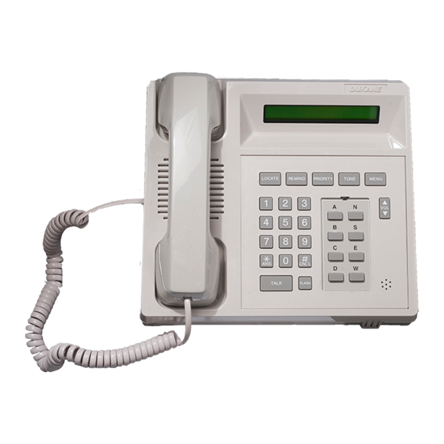
Base Master Features The base master has five function buttons across the top (LOCATE, REMIND, PRIORITY, TONE, and MENU), a standard 12-character key pad, eight configurable buttons (default-labeled A, B, C, D, N, S, E, W), a volume (VOL) button, TALK and FLASH buttons, and a handset. -
Page 22: Error (Err) Tone
Base Master Features Error (ERR) Tone If a function is inaccessible or a function is performed incorrectly, the base master sounds two rapid, low pitch tones. Busy Tone If the base master attempts to connect to a station that is already in communication with another base master, the universal busy tone sounds. -
Page 23: Base Master Layout
Base Master Layout Base Master Layout Display Window The base master has a 16-character alphanumeric LCD window that shows system states, active conditions, and call status. It also shows programming functions, operating func- tions, and menu selections. The base master has a number of “states” that indicate the base master’s current function, such as the idle state (when no calls are present), the connect state (when the base master is connected to a call), and the editing state (when the base master is being used to per- form system configuration). -
Page 24: Cancel (#Cncl) Key
Base Master Layout Cancel (#CNCL) Key This key is pressed to end communication with a station. (When the handset is used, it is not necessary to press #CNCL. Communication ends when the handset is placed back into its cradle.) This key is also used to end a programming function and to reverse-step back to the original default display if you are in a programming or scanning function. -
Page 25: Function Buttons
Base Master Layout Function Buttons The base master has five function buttons: LOCATE, REMIND, PRIORITY, TONE, and MENU. The LOCATE button is used to view registered staff locations. See page 2-15 for details. The REMIND button is used to place a call on reminder or to view calls previously placed on reminder. -
Page 26: Idle/Time Display
Idle/Time Display Idle/Time Display The base master is in the idle state when there are no active conditions in the system (e.g., calls, errors, or failures). The words ProCare 6000 and the current time (in 24-hour format) alternate in the display window. A flashing heartbeat (small square) appears in the lower right corner of the display window to show that the base master is operable. -
Page 27: Flashing Display Codes
Flashing Display Codes Flashing Display Codes This section contains a quick reference list of the possible codes that may appear on the right side of the base master display window. “Answered call”—Indicates a locking call that has previously been answered. See Pending Call Display on page 2-1. -
Page 28: Optional Four-Line Display
Optional Four-Line Display Optional Four-Line Display A Dukane Model 438-815A Supple- mental Four-Line Master Station Display is an optional accessory that mounts onto your base master to dis- play additional calls. See Figure 1-4. It can display up to four incoming calls in addition to the first call displayed on the base master. -
Page 29: Following Instructions
Following Instructions Following Instructions Following this manual will be easier if you know how the instructions are presented. Default Settings The instructions and graphics in this manual are based on the default base master and sys- tem settings. If your system has been configured differently, note these differences in the areas provided or in the margins. -
Page 30: Display Prompts And Messages
Base Master Care Display Prompts and Messages The display prompts and messages are written as they appear in the display and enclosed in quotation marks. Example: “Rem Scan:RED =1” Station numbers, staff ID numbers, and other system information used as examples are enclosed in parentheses. -
Page 31: Section 2-Base Master Operations
Section Base Master Operations Introduction This section explains how to place and answer calls and how to perform these functions while connected to a call: assign staff to patients, send pocket pages, assign call priorities to stations, and use the remind and locate features. Video Display Interactions If your ProCare 6000 System is equipped with one or more video displays, some of the functions described in this section MUST be performed using those displays INSTEAD... -
Page 32: Answering A Call
Answering a Call 1040 NORM of 3 Figure 2-2: Pending Call Display with Three Calls Locking calls that have previously been answered appear with a flashing “Ac” (answered call). Code blue, staff emergency, and lavatory calls are locking calls because they cannot be canceled at the base master—only at the stations that placed the calls. -
Page 33: Selectively Answering A Pending Call (Vol, *Ans)
Answering a Call 1011 TALK Figure 2-4: Automatically Answering the Last Call 2. Either press the TALK button to communicate with the station (and release it to listen), or lift the handset to communicate privately with the station. 3. Press *ANS to end this call and auto answer the next unanswered call. If there are no more pending calls, the heartbeat appears at the far right of the display. -
Page 34: Placing A Call
Placing a Call Placing a Call Placing a Call Using the Key Pad and Alpha Keys Follow these steps to call a station using the base master’s key pad and alpha keys. (Al- pha keys are only used if the station number includes a letter; e.g., 101A.) 1. -
Page 35: Placing A Call Using Speed Dial
Placing a Call Placing a Call Using Speed Dial Speed dial is only available if any of your base master’s alpha keys have been configured as speed dial keys. These keys can be configured to dial a station number, a staff ID, a station prefix, or other functions. -
Page 36: Assigning Staff To A Station While Connected To A Call
Assigning Staff to a Station While Connected to a Call Assigning Staff to a Station While Connected to a Call Assigning Primary Staff (MENU, 3, 1) Follow these steps to assign a primary staff member to a station while connected to the station. -
Page 37: Assigning Alternate Staff (Menu, 3, 2)
Assigning Staff to a Station While Connected to a Call 5. Enter the new staff assignment. If the ID number is shorter than the number of digits shown on the display, press *ANS. a. “Waiting for Resp” (response) appears briefly. b. -
Page 38: Sending A Pocket Page While Connected To A Call
Sending a Pocket Page While Connected to a Call nAsID#> _ _ _ _ Figure 2-10: New Alternate Staff Assignment 5. Enter the new staff assignment. If the ID number is shorter than the number of digits shown on the display, press *ANS. a. -
Page 39: Paging Primary Staff (Menu, 5, 1)
Sending a Pocket Page While Connected to a Call Paging Primary Staff (MENU, 5, 1) Follow these instructions to page the primary staff member assigned to a selected station, and transmit the station number and an optional two-digit coded message relating to that patient. -
Page 40: Paging Alternate Staff (Menu, 5, 2)
Sending a Pocket Page While Connected to a Call Paging Alternate Staff (MENU, 5, 2) Follow these instructions to page the alternate staff member assigned to a selected station, and transmit the station number and an optional two-digit coded message relating to that patient. -
Page 41: Paging Staff By Staff Id Number (Menu, 5, 3)
Sending a Pocket Page While Connected to a Call Paging Staff by Staff ID Number (MENU, 5, 3) Follow these instructions to page staff members by their staff ID numbers. Notes: If your system has version 4.XX video displays, use the video display to perform •... -
Page 42: Paging Staff By Pager Id Number (Menu, 5, 4)
Sending a Pocket Page While Connected to a Call Paging Staff by Pager ID Number (MENU, 5, 4) Follow these instructions to page a staff member by pager number, and transmit the sta- tion number and an optional two-digit coded message relating to that patient. Notes: If your system has version 4.XX video displays, use the video display to perform •... -
Page 43: Pocket Pager Messages
Sending a Pocket Page While Connected to a Call Pocket Pager Messages Code Message Code Message Chart 2-1: Pocket Pager Messages ProCare 6000 Operation Manual 2-13... - Page 44 Sending a Pocket Page While Connected to a Call Code Message Code Message ProCare 6000 Operation Manual 2-14...
-
Page 45: Using The Locate Button
Using the LOCATE Button Using the LOCATE Button Viewing Staff Locations The LOCATE button is used to view stations where staff have registered their presence (does not work with IR location). You can view staff locations by staff level only. 1. -
Page 46: Using The Remind Button
Using the REMIND Button Using the REMIND Button Placing a Call on Reminder When a call is placed on reminder, it reappears at the base master after a preprogrammed interval if a staff member does not attend to the patient and cancel the call. It will con- tinue to reappear at the base master until it is canceled at the station that placed the call. -
Page 47: Canceling A Reminder
Using the REMIND Button Canceling a Reminder If there are reminders in the system, the idle display flashes “RR,” “RG,” or “RA” (default settings) to indicate the levels of reminders set. See Figure 2-17 on page 2-16. After a pre- programmed interval, the reminder calls reappear at the base master. -
Page 48: Viewing And Connecting To Set Reminders
Using the REMIND Button Viewing and Connecting to Set Reminders Follow these steps to view previously set reminders. You can only do this when the base master is not in communication with a station. 1. Press REMIND. These selections are available: DEFAULT YOUR SYSTEM Rem Scan: RED = 1... -
Page 49: Using The Priority Button
Using the PRIORITY Button Using the PRIORITY Button Assigning Station Call Priorities To assign a call priority to a station, your base master must cover the station to be changed, either by capturing, swinging, sharing, or permanent coverage. —IMPORTANT UL NOTICES— A patient normal call is canceled when it is answered at the master station, or when the CANCEL button is pressed on the station that placed the call. -
Page 50: Assigning Station Auxiliaries Or Station Prime Auxiliaries
Using the PRIORITY Button 4. Scroll up/down using the VOL key to display a new priority, then press *ANS. —OR— Press the number of the call priority you wish to assign to the station. a. “Waiting for Resp” (response) appears briefly. (If “OwnerOut” appears, see page 2-23.) b. -
Page 51: Assigning Team Pagers To A Station
Using the PRIORITY Button 4. Press the number of the station auxiliary you wish to assign to the station. a. “Waiting for Resp” (response) appears briefly. (If “OwnerOut” appears, see page 2-23.) b. The call reappears in the display window followed by “TALK.” 5. -
Page 52: Using The Tone Button
Using the TONE Button Using the TONE Button Silencing Pending Call Tones 1. Press TONE to silence pending calls or reminder recalls. (If pressing TONE does not silence the tone, this function may have been deactivated at your base master.) a. -
Page 53: The "Ownerout" Message
The “OwnerOut” Message The “OwnerOut” Message If another base master fails, you will see the “OwnerOut” message at your base master every time you: Change the priority of a station that is covered by the failed master. • Change the primary or alternate staff assignment of a station covered by the failed •... - Page 54 Notes ProCare 6000 Operation Manual 2-24...
-
Page 55: Section 3-Menu Operations
Section Menu Operations Introduction This section explains how to use the base master’s menu items to perform various functions. Please keep the following in mind: Some of these menu selections may not be available depending on the configuration of • your system. -
Page 56: Auto-Dialing (Menu, 1)
Auto-Dialing (MENU, 1) Auto-Dialing (MENU, 1) This menu selection allows you to auto-dial a station. Up to eight auto-dial numbers can be assigned during system configuration. (See the chart below.) 1. Press MENU. 2. Press 1 to select Auto-Dial = 1. The first programmed auto-dial number appears in the display followed by “autoDial.”... -
Page 57: Placing The Master On/Off Duty (Menu, 2)
Placing the Master On/Off Duty (MENU, 2) Placing the Master On/Off Duty (MENU, 2) This menu selection allows you to place the base master on duty or off duty. Notes: Incoming calls still tone and display at an off duty base master. You can still place and answer calls from an off duty base master. -
Page 58: Assigning Base Masters, Staff, And Stations (Menu, 3)
Assigning Base Masters, Staff, and Stations (MENU, 3) Assigning Base Masters, Staff, and Stations (MENU, 3) Capturing Base Master Coverage (MENU, 3, 1, 1) This menu selection allows you to capture another base master’s coverage. This allows you to respond to calls placed in the captured base master’s coverage area. Calls can still be answered at the captured base master. -
Page 59: Figure 3-6: Capturing Base Master's Display Showing Captured Base Masters
Assigning Base Masters, Staff, and Stations (MENU, 3) 6. Press #CNCL repeatedly to exit the menu and return to the normal display. If you do not, the base master automatically exits the menu after a programmed interval. When your base master is idle, it will flash “C<” at the far right of its display to indicate that it is covering another base master’s calls. -
Page 60: Sharing Base Master Coverage (Menu, 3, 1, 2)
Assigning Base Masters, Staff, and Stations (MENU, 3) Sharing Base Master Coverage (MENU, 3, 1, 2) This menu selection allows two-way sharing of calls between base masters. It allows an attendant at any shared base master to respond to calls in another base master’s shared coverage area as well as his/her own area. -
Page 61: Figure 3-10: Display Showing A Shared Base Master
Assigning Base Masters, Staff, and Stations (MENU, 3) When your base master is idle, it will alternately flash “C<” at the far right of its display, the number of masters shared (if more than one), and “c>” to indicate that it is sharing call coverage with other base masters. -
Page 62: Releasing Captured And Shared Base Masters (Menu, 3, 1, 3)
Assigning Base Masters, Staff, and Stations (MENU, 3) Releasing Captured and Shared Base Masters (MENU, 3, 1, 3) This menu selection allows you to release captured and shared base masters. Note: You cannot release your own base master if it is captured. The release must be performed by the capturing base master. -
Page 63: Scanning Captured And Shared Base Masters (Menu, 3, 1, 4)
Assigning Base Masters, Staff, and Stations (MENU, 3) Scanning Captured and Shared Base Masters (MENU, 3, 1, 4) This menu selection allows you to scan the base masters captured and shared by your base master. 1. Press MENU. 2. Press 3 to select Assignments = 3. 3. -
Page 64: Assigning Primary Staff To Stations (Menu, 3, 2, 1)
Assigning Base Masters, Staff, and Stations (MENU, 3) Assigning Primary Staff to Stations (MENU, 3, 2, 1) This menu selection allows you to assign a primary staff member to a station. The station MUST be covered by your base master, either by capturing, by swinging, or by coverage assignment. -
Page 65: Assigning Alternate Staff To Stations (Menu, 3, 2, 2)
Assigning Base Masters, Staff, and Stations (MENU, 3) 6. Enter the new primary staff ID. If the ID is shorter than the number of digits shown on the display, press *ANS. a. “Waiting for Data” and “Waiting for Resp” (response) appear briefly. b. -
Page 66: Creating Staff Ids (Menu, 3, 2, 3)
Assigning Base Masters, Staff, and Stations (MENU, 3) 5. Enter the station number. If the number is shorter than the number of spaces in the display, press *ANS. a. The old alternate staff number appears briefly (oAsID#), then the prompt for the new staff number (nAsID# _ _ _ _ _ _). -
Page 67: Swinging A Station To Your Base Master (Menu, 3, 3, 1)
Assigning Base Masters, Staff, and Stations (MENU, 3) 3. Press 2 to select Assign Staff = 2. StafId> _ _ _ _ _ Figure 3-17: Creating Staff IDs 4. Press 3 to select Create StaffID = 3. Figure 3-17 appears: 5. -
Page 68: Swinging A Station To A Duty Area (Menu, 3, 3, 2)
Assigning Base Masters, Staff, and Stations (MENU, 3) 5. Enter the number of the swing station to be assigned to this master. If the number is shorter than the number of spaces in the display, press *ANS. a. “Waiting for Data,” “Waiting for Access,” and “Waiting for Resp” (response) appear briefly. -
Page 69: Figure 3-19: Assigning Swing Stations To A Duty Area
Assigning Base Masters, Staff, and Stations (MENU, 3) nDA#> _ _ _ _ _ _ _ _ _ Figure 3-19: Assigning Swing Stations to a Duty Area 6. Enter the new duty area and press *ANS. a. “Waiting for Data” appears briefly. If the duty area name is valid, an acceptance tone sounds (two high pitch beeps) and the base master returns to Figure 3-19. -
Page 70: Performing Audio Page Functions (Menu, 4)
Performing Audio Page Functions (MENU, 4) Performing Audio Page Functions (MENU, 4) Note: This is an optional feature. Your system may not be equipped for audio paging. Performing a Hallway Page (MENU, 4, 1) You can make a page announcement to any stations that are set up as hallway stations. Note: Performing hallway pages can tie up the audio line. -
Page 71: Performing An All Page (Menu, 4, 2)
Performing Audio Page Functions (MENU, 4) Performing an All Page (MENU, 4, 2) You can page all stations in your local area group (LAG). You cannot page stations in other LAGs. Notes: If a station calls your base master, and another base master pages that station before you answer its call, the call will be suspended during the page, then automatically reinstated as soon as the page ends. -
Page 72: Performing A Base Master Page (Menu, 4, 3)
Performing Audio Page Functions (MENU, 4) Performing a Base Master Page (MENU, 4, 3) You can page all stations covered by your base master. If your base master has captured another master, the captured master’s stations will also receive the page. Notes: If a station calls your base master, and another base master pages that station before you answer its call, the call will be suspended during the page, then automatically... -
Page 73: Performing An Area Page (Menu, 4, 4)
Performing Audio Page Functions (MENU, 4) Performing an Area Page (MENU, 4, 4) Your system has been configured with up to eight paging groups. A group consists of one to eight duty areas and all the stations assigned to those duty areas. You can page one of these groups. -
Page 74: Performing Pocket Page Functions (Menu, 5)
Performing Pocket Page Functions (MENU, 5) Performing Pocket Page Functions (MENU, 5) Note: This is an optional feature. Your system may not be equipped for pocket paging. Paging Primary Staff (MENU, 5, 1) You can send a page to the primary staff member assigned to a station. The page will in- clude the station number and an optional two-letter coded message relating to the patient. -
Page 75: Paging Alternate Staff (Menu, 5, 2)
Performing Pocket Page Functions (MENU, 5) 6. Either press *ANS to page the staff person without sending a message, or enter a two-digit pager message number. (See Pocket Pager Messages on page 2-13.) a. “Waiting for Resp” (response) appears briefly. b. -
Page 76: Paging Staff By Staff Id Number (Menu, 5, 3)
Performing Pocket Page Functions (MENU, 5) Paging Staff by Staff ID Number (MENU, 5, 3) You can page staff members by their staff ID numbers. Notes: If your system has version 4.XX video displays, use the video display to perform •... -
Page 77: Paging Staff By Pager Number (Menu, 5, 4)
Performing Pocket Page Functions (MENU, 5) Paging Staff by Pager Number (MENU, 5, 4) You can page staff members by their pager numbers. Notes: If your system has version 4.XX video displays, use the video display to perform • this function instead of the base master. If your system has version 5.XX video displays, no pocket paging functions can be •... -
Page 78: Assigning A Pager Number To A Staff Member (Menu, 5, 5)
Performing Pocket Page Functions (MENU, 5) Assigning a Pager Number to a Staff Member (MENU, 5, 5) This menu selection allows you to assign a pager number to a staff member. Notes: If your system has version 4.XX video displays, use the video display to perform •... -
Page 79: Assigning A Charge Pager Number (Menu, 5, 6)
Performing Pocket Page Functions (MENU, 5) Assigning a Charge Pager Number (MENU, 5, 6) This menu selection allows you to designate a pager as a charge pager. This pager is al- ways given to the charge person on each shift. It is paged any time a call is still pending after two timeout periods. -
Page 80: Creating Pager Numbers (Menu, 5, 7)
Performing Pocket Page Functions (MENU, 5) Creating Pager Numbers (MENU, 5, 7) This menu selection allows you to create new pager numbers. Notes: If your system has version 4.XX video displays, use the video display to perform • this function instead of the base master. If your system has version 5.XX video displays, no assignment functions can be •... -
Page 81: Changing Tone, Date, And Time Settings (Menu, 6)
Changing Tone, Date, and Time Settings (MENU, 6) Changing Tone, Date, and Time Settings (MENU, 6) Setting the Tone Level (MENU, 6, 1) This function allows you to set the tone level (volume) for the base master. Note: The tone levels for on duty and off duty status are set independently. Place the base master on duty to set on duty tone levels, then place the base master off duty to set off duty tone levels. -
Page 82: Setting The Date And Time (Menu, 6, 2)
Changing Tone, Date, and Time Settings (MENU, 6) Setting the Date and Time (MENU, 6, 2) This function allows you to set the base master’s date and time. Notes: If your base master has an associated video display, you should still set the date and time at the base master. -
Page 83: Base Master Errors
Base Master Errors Base Master Errors If your base master indicates errors (a flashing “E” in the right corner, and a continuous error tone of two rapid, low pitch tones), press the TONE button to silence the tone, and contact the proper authority. If you are the person authorized to deal with base master errors, see Reviewing Master Station Error Listings in the ProCare 6000 System Installa- tion and Configuration Manual for instructions. -
Page 84: Configurable Buttons
See the ProCare 6000 System Installation and Config- uration Manual. Dukane recommends that the person responsible for programming the base master record the assigned functions in the chart below. Dukane also recommends making extra copies of the blank chart for possible future reconfiguration. Chart 3-3: Configurable Buttons... -
Page 85: Section 4-Station Operations
Section Station Operations Introduction This section covers the operation of three different stations: Single patient station (Model 4A2481) Staff/duty station (Model 4A2495) • • Dual patient station (Model 4A2486) • It also covers the operation of single-gang stations, pillow speakers, call cords, and call cord adapters. -
Page 86: The Code Button
Single and Dual Patient Stations The dual patient station is normally mounted in the head wall between the patient beds. It is pictured in Figure 4-2. CALL CALL CODE STAFF CANCEL ALIGN CONNECTOR TAB ALIGN CONNECTOR TAB Figure 4-2: Model 4A2486 Dual Patient Station Note: If your system has custom stations, the button descriptions in this manual may not match your stations. -
Page 87: Canceling A Code Blue Call
Single and Dual Patient Stations Canceling a Code Blue Call Code blue calls can only be canceled by pressing the CANCEL button on the station that placed the call. When a code blue call is canceled, the following things occur: •... -
Page 88: The Aux Button
Single and Dual Patient Stations The AUX Button Pressing this button places an auxiliary call to the base master station. (Dual patient sta- tions will send two calls, a left bed and a right bed, when this button is pressed.) The meaning of such a call is programmable at the master station. -
Page 89: The Bed Light
Single and Dual Patient Stations If the system monitor function is active, the CANCEL button also silences incoming call tones. The light on the CANCEL button flashes when the system monitor function is active. (See The System Monitor Function on page -.) The light on the CANCEL button will also illuminate to indicate when an audio connec- tion has been established with the patient. -
Page 90: Canceling An Auxiliary Call
The CALL Light Canceling an Auxiliary Call Auxiliary calls can only be canceled from the equipment responsible for the call. In the case of the AUX button on patient stations, the station itself is responsible for the call. So, you can press the CANCEL button to cancel. For all other auxiliary calls, you must resolve the problem that caused the call, reset the auxiliary monitor equipment that sig- naled the difficulty, or unplug the equipment and insert a dummy plug in its place. -
Page 91: Canceling A Patient Call
The CALL Light Canceling a Patient Call All patient calls can be canceled by pressing the CANCEL button on the patient station. Normal patient calls can also be canceled by registering staff presence within the pa- tient’s room. Normal patient calls can also be canceled by answering them at the base master station. -
Page 92: Staff/Duty Stations
Staff/Duty Stations Staff/Duty Stations Staff/duty stations can be located in any area where staff members may be temporarily working. The station can be preprogrammed to monitor the system, alerting the staff to any patient calls by sounding a tone. The staff/duty station is shown below. CODE STAFF DUTY... -
Page 93: The System Monitor Function
The System Monitor Function The System Monitor Function When the system monitor is activated, all calls (normal, priority, emergency, and re- minder recall) will flash and tone at the monitoring stations. Depending on how your system is configured, the system monitor can be in master, staff, or duty mode: In master mode, a monitoring station will flash and tone for any calls placed from sta- •... -
Page 94: Registering Staff Presence
Registering Staff Presence Registering Staff Presence Staff presence can be registered at pres- ence stations (Figure 4-4), at staff/ duty stations with presence (Figure A-4 on page A-6), and by entering a room while wearing an IR (infrared) location badge. Presence is an optional feature, and your ProCare 6000 System may be equipped with presence stations, IR location, or... -
Page 95: Removing A Registered Presence
Registering Staff Presence Removing a Registered Presence In systems equipped with IR location, presence is automatically removed when the staff member IR badge is sensed in another location. To remove a registered presence using a presence station, press the illuminated red, am- ber, or green button on the station that corresponds to your registered staff level (Figure 4-4 on the preceding page). -
Page 96: Placing An Emergency Call
Placing an Emergency Call Placing an Emergency Call Placing an Emergency Call From a Pull Cord Lavatory or Shower Station Either pull the station’s cord, or press the PULL FOR HELP button. See Figure 4-5. When you do, this happens: The station’s call assurance LED illuminates to confirm call placement. -
Page 97: Placing An Emergency Call From A Pushbutton Lavatory Station
Placing an Emergency Call Placing an Emergency Call From a Pushbutton Lavatory Station Press the station’s PUSH FOR HELP button. See Figure 4-6. When you do, this happens: The station’s call assurance LED illuminates to • confirm call placement. The call appears at the base master and the video •... -
Page 98: Placing An Emergency Call From A Staff Emergency Station
Placing an Emergency Call Placing an Emergency Call From a Staff Emergency Station Press the station’s STAFF button. See Figure 4-8. When you do, this happens: The station’s call assurance LED illuminates to • confirm call placement. The call appears at the base master and the video •... -
Page 99: Auxiliary Call Functions
Auxiliary Call Functions Auxiliary Call Functions Auxiliary calls are placed by auxiliary monitor equipment that is either connected to the patient station through a call cord adapter (see pages 4-25 and 4-26), or connected to an auxiliary station that is wired to the patient station’s auxiliary inputs (see page 4-16). Each patient station’s auxiliary inputs can be individually assigned to a particular type of device as needed. -
Page 100: Auxiliary Station Operation
The 9A2130 call cord station is located in ancillary areas. The cord receptacle accepts any standard Dukane call cord. (See Cord Assemblies on page 4-27.) When a call cord is connected to the station, it can place a normal patient call to the base master. -
Page 101: Dual 37-Pin Receptacle Operation
Dual 37-Pin Receptacle Operation To cancel the call, press the station’s CANCEL button. When you do, this happens: The station’s call assurance LED extinguishes. • The associated corridor light extinguishes. • The tone ceases at the duty stations. • The call disappears from the base master and video display (if present). •... -
Page 102: Station Care
Station Care Station Care The stations can be wiped down with a damp cloth, or with any disinfectant typically used by hospital maintenance (e.g., Sidex, Staphine, or a 10% bleach/water solution). Pillow Speaker Descriptions The pillow speaker instructions on the follow- ing pages are based on the default system settings. -
Page 103: Model 7A/B/C2116
“i” button to control the TV closed-caption function. Model 7A/B/C2131 The 7A/B/C2131 smart pillow speakers can be used with all Dukane ProCare 6000 special purpose patient stations. These smart pillow Figure 4-14: Smart Pillow Speaker speakers provide nurse call, lighting controls, (Models 7A/B/C2116) and TV control of “smart”... -
Page 104: Pillow Speaker Buttons And Functions
Pillow Speaker Buttons and Functions Pillow Speaker Buttons and Functions The pillow speakers are all basically the same, however, some buttons and functions may differ slightly depending on your system’s configuration. Note these differences in the margins. All pillow speakers place calls in the same manner. The call’s priority and associated cor- ridor light and flash rates are determined by patient priority, station type, and system configuration. - Page 105 Pillow Speaker Buttons and Functions Connector Depending on the pillow speaker model, this multi-pin connector either plugs into the patient station or into a receptacle in the wall near the floor. TV Button Press this button to control television functions. Depending on your system configuration, it will either turn the TV on/off and step through the channels, or it will only turn the TV on/off.
-
Page 106: Pillow Speaker Operations
Pillow Speaker Operations Pillow Speaker Operations Placing a Normal Call from a Pillow Speaker 1. Press the large nurse call button. See Figure 4-16 on page 4-20. When you do, this happens: • The green LED behind the translucent nurse call button illuminates to confirm call placement. -
Page 107: Canceling A Call Placed From A Pillow Speaker
Pillow Speaker Operations Canceling a Call Placed from a Pillow Speaker Canceling a call placed from a pillow speaker is basically the same as canceling calls placed from patient stations. See below. Canceling a Normal Call A normal call is automatically canceled when the base master answers the call or when the patient station’s CANCEL button is pressed. -
Page 108: Canceling A Priority Or Reminder Call
Pillow Speaker Care Canceling a Priority or Reminder Call Priority and reminder calls can only be canceled at the patient station associated with the pillow speaker that placed the call. Either press the CANCEL button on the patient station, or register staff presence in the room. -
Page 109: Call Cord Adapters
Call Cord Adapters Call cord adapters are connected to the patient station when call cords are needed in place of or in parallel with the Dukane pillow speaker. Model 570-303A Call Cord Adapter Use the 570-303A adapter when you need to con- nect both a call cord and a pillow speaker to a patient station. -
Page 110: Model 570-305 Call Cord Adapter With Auxiliary Input
Call Cord Adapters Model 570-305 Call Cord Adapter with Auxiliary Input Use the 570-305 adapter when you need to con- nect a call cord, an auxiliary device, and a pillow speaker to a patient station. (This adapter can also be used with a call cord or auxiliary device only.) Note: This adapter can ONLY be used with patient stations that have a red LED labeled AUX... -
Page 111: Model 570-306 Call Cord Adapter With Auxiliary Input
Air cord assemblies provide a pressure-activated means of placing a call from an oxygen tent. They can be used in place of or in parallel with the Dukane pillow speaker normally connected to the patient station. These cords can be washed and sterilized but are not immersible. -
Page 112: Models 200-446 And 200-447 Single Air Cord Assemblies
Cord Assemblies Models 200-446 and 200-447 Single Air Cord Assemblies These assemblies provide nurse call capabilities to a patient with one patient station. They are spe- cifically designed for patients undergoing oxygen therapy. Model 200-446 is 6 feet (1.8 m) long. Model 200-447 is 10 feet (3.0 m) long. -
Page 113: Model 200-1072 Air Operated Pushbutton Cord Assembly
Cord Assemblies Model 200-1072 Air Operated Pushbutton Cord Assembly This assembly provides nurse call capabilities to a patient with one patient station. It is specifically designed for patients undergoing oxygen therapy. This assembly has a pushbutton actuator for pa- tients with impaired dexterity. Model 200-1072 is 8 feet (2.4 m) long. -
Page 114: Model 200-1272 Call Cord Assembly
Cord Assembly Care Model 200-1272 Call Cord Assembly This assembly provides nurse call capabilities to one patient with one patient station. It has a non-locking, momentary pushbutton switch. Model 200-1272 is 12 feet (3.7 m) long. Figure 4-27: Call Cord Assembly (Model 200-1272) Model 570-131 Dummy Plug Removing a call cord, air cord, or other device... -
Page 115: Corridor Light Colors And Flash Rates
Corridor Light Colors and Flash Rates Corridor Light Colors and Flash Rates These charts show the default corridor light colors and flash rates for designated calls. If your system has been configured differently, note the changes in the margins. Note: In the charts, “ppm”... -
Page 116: Staff/Duty Station Led Flash Rates And Tone Rates
Staff/Duty Station LED Flash Rates and Tone Rates Staff/Duty Station LED Flash Rates and Tone Rates Pending calls and reminder recalls will tone and flash the presence LEDs at staff/duty sta- tions and at stations where the system monitor is activated. These charts show the default LED flash rates and tone rates for designated calls. -
Page 117: Section 5-Telephone (Telco) Interface Operations
Section Telephone (Telco) Interface Operations Introduction The telephone interface (Telco) allows you to use a standard telephone to answer calls from stations and place calls to patient or staff stations. Notes: This is an optional feature. If you are unsure whether or not your system includes this feature, ask the appropriate authority at your facility. -
Page 118: Staff Id Number
Functions and Basic Instructions Staff ID Number This is the ID number assigned to each staff member. You must enter your staff ID num- ber to answer the calls from stations assigned to you. Note: If your system has version 5.XX video displays, staff IDs are not used. ProCare 6000 systems with 5.XX video displays use MatchMaker ip to enter staff names. -
Page 119: Placing A Call From A Telephone
Placing a Call from a Telephone Placing a Call from a Telephone 1. Lift the telephone handset. 2. Enter the Telco extension number. (See the extensions on page 5-1.) A basic telephone ring and a short chirp confirm that you have accessed the Telco. (If the Telco is in use you will hear a busy signal.) 3. -
Page 120: Answering A Call
Answering a Call Answering a Call Answering a Call from a Station Assigned to You You can use your staff ID number to answer calls only from those stations for which you are the primary staff member. Notes: If your system has version 5.XX video displays and MatchMaker ip software, •... -
Page 121: Answering A Call From Any Station
Answering a Call Answering a Call from Any Station You can answer calls placed from any station covered by your Telco card, regardless of whether or not you are assigned to the station: 1. Lift the telephone handset. 2. Enter the Telco extension number. (See the extensions on page 5-1.) A basic telephone ring and a beep confirm that you have accessed the Telco. -
Page 122: Placing A Call On Reminder
Placing a Call on Reminder Placing a Call on Reminder 1. Connect to a station by placing or answering a call. (See page 5-3 or 5-4.) 2. Press 1 (red), 2 (amber), or 3 (green) on the key pad to set the desired reminder level. The reminder is set. -
Page 123: Paging Hallway Speakers From A Telephone
Paging Hallway Speakers from a Telephone Paging Hallway Speakers from a Telephone 1. Lift the telephone handset. 2. Enter the Telco extension number. (See the extensions on page 5-1.) A basic telephone ring and a beep confirm that you have accessed the Telco. (If the Telco is in use you will hear a busy signal.) 3. - Page 124 Notes ProCare 6000 Operation Manual...
-
Page 125: Section 6-Quick Charts
Section Quick Charts Introduction This section provides quick reference charts for the ProCare 6000 base master. Basic Operation Chart—page 6-2 This chart is a quick reference of base master operations. Detailed Menu Chart—page 6-4 This chart shows the functions available within the basic menu operations. Telco Basic Operation Chart—page 6-10 This chart is a quick reference of Telco operations. -
Page 126: Basic Operation Chart
Basic Operation Chart Basic Operation Chart These charts provide a quick reference of base master operations. You should have a basic understanding of base master operations before using these charts. For detailed information on a particular function, see the referenced page number. OPERATION ACTION RESULT... - Page 127 Basic Operation Chart OPERATION ACTION RESULT Scanning Reminders Press REMIND. The display scrolls staff reminders by the Select the reminder level. selected level. page 2-18 Press *ANS to connect to the displayed station. Press #CNCL to end. Scanning Staff Locations Press LOCATE.
-
Page 128: Detailed Menu Chart
Detailed Menu Chart Detailed Menu Chart These charts describe the functions available within each menu selection. For detailed in- formation on a particular function, see the referenced page number. Note: In some situations, pressing *ANS after entering a selection is optional. After a two-second delay, the system automatically advances to the next step. - Page 129 Detailed Menu Chart MENU FUNCTION ACCESS SEQUENCE RESULTS Assign Staff = 2 Press MENU, 3, 2. Assigns primary and alternate These functions scroll: staff members to stations, and BedToPrimStaff = 1 creates staff ID numbers. BedTo AltStaff = 2 Create StaffID = 3 BedToPrimStaff = 1 Press MENU, 3, 2, 1.
- Page 130 Detailed Menu Chart MENU FUNCTION ACCESS SEQUENCE RESULTS Assign Swing = 3 Press MENU, 3, 3. Swings stations between base These functions scroll: masters and duty areas. SwingBedToMstr = 1 SwingBedToDuty = 2 SwingBedToMstr = 1 Press MENU, 3, 3, 1. Swings a station to your base Enter station number.
- Page 131 Detailed Menu Chart MENU FUNCTION ACCESS SEQUENCE RESULTS Master Page = 3 Press MENU, 4, 3. Transmits a page to the selected Select an option: stations covered by the base page 3-18 1 = All Stations master. 2 = Staff Only 3 = Red Only 4 = Amber Only 5 = Green Only...
- Page 132 Detailed Menu Chart MENU FUNCTION ACCESS SEQUENCE RESULTS Page Staff ID# = 3 Press MENU, 5, 3. Transmits a message to a staff Enter staff number. member by staff ID #. page 3-22 Enter message code. Page is sent. Page Pager ID# = 4 Press MENU, 5, 4.
- Page 133 Detailed Menu Chart MENU FUNCTION ACCESS SEQUENCE RESULTS Set Tone Level = 1 Press MENU, 6, 1. Adjusts tone level of incoming Press VOL to desired tone level. base master tones. page 3-27 Press *ANS to set tone level. Press #CNCL. Set Date &...
-
Page 134: Telco Basic Operation Chart
Telco Basic Operation Chart Telco Basic Operation Chart These charts describe the functions of the Telco telephone interface. For detailed infor- mation on a particular function, see the referenced page number. OPERATION ACTION RESULT Placing a Call Enter the Telco extension number. Your telephone connects to the (to a station) Press *. - Page 135 Telco Basic Operation Chart OPERATION ACTION RESULT Answering a Call Enter the Telco extension number. Your telephone connects to the (placed from any station) Enter your staff ID number. unanswered call with the highest The telephone connects to the highest priority.
- Page 136 Notes ProCare 6000 Operation Manual 6-12...
-
Page 137: Section A-Four-Gang Station Operations
• These stations are built on a four-gang chassis. If your facility has the new, smaller (three-gang) Dukane stations, see Section 4 of this manual for operation instruc- tions. Patient stations can be single or dual. They are normally located in the headwall adjacent to each station and can interface with special station applications and auxiliaries. -
Page 138: Code Blue
Station Button Descriptions STAFF CODE CALL EMERG CALL BLUE SYSTEM CANCEL CALL MONITOR SECRECY ALIGN CONNECTOR TAB ALIGN CONNECTOR TAB Figure A-1: Dual Patient Station Showing Common Buttons (Model 4A2386A) CODE BLUE This button sends a code blue call to the base master. See page A-5. STAFF EMERGENCY (STAFF EMERG) This button sends a staff emergency call to the base master. -
Page 139: Secrecy
Basic Station Operations SECRECY This button places the station into secrecy mode, in which the base master attendant cannot hear any sound from the station. See page A-7. CANCEL This button cancels any calls placed from this station. On staff/duty stations, this button also silences incoming call tones when the system monitor function is activated. -
Page 140: Placing A Normal Call
Basic Station Operations Placing a Normal Call Press the station’s CALL button to place a normal call from a patient or staff/duty station. See Figure A-3. When you do, this happens: The station’s CALL LED illuminates to confirm call placement. •... -
Page 141: Canceling A Normal Call
Basic Station Operations Canceling a Normal Call Press the station’s CANCEL button to cancel a normal call from a patient or staff/duty station. (This will also cancel any calls of other priorities placed from this station.) See Figure A-3 on page A-4. When you do, this happens: The station’s CALL LED extinguishes. -
Page 142: Canceling A Priority Call
Basic Station Operations Canceling a Priority Call Press the station’s CANCEL button to cancel a code blue, staff emergency, or pro- grammed priority call placed from a patient or staff/duty station. See Figure A-3 on page A-4. When you do, this happens: The station’s CALL LED extinguishes. -
Page 143: Activating Secrecy
Basic Station Operations When you do, this happens: The station’s CALL LED extinguishes. • The associated corridor light extinguishes. • Note: When presence is registered, the section of the corridor light that corresponds to the registered presence level stops flashing and steadily illuminates. The reminder recall disappears from the base master display and the video display •... -
Page 144: The System Monitor Function
Basic Station Operations The System Monitor Function When the system monitor is activated, all calls (normal, priority, and recall) will flash and tone at the monitoring stations. Depending on how your system is configured, the system monitor can be in master mode, staff mode, or duty mode: In master mode, a monitoring station will flash and tone for any calls placed from sta- •... -
Page 145: Figure A-5: Staff/Duty Station (Model 4A2395A)
Basic Station Operations SYSTEM CALL MONITOR CODE STAFF BLUE EMERG SECRECY CANCEL Figure A-5: Staff/Duty Station (Model 4A2395A) STAFF CODE CALL EMERG CALL BLUE SYSTEM CALL CANCEL MONITOR SECRECY ALIGN CONNECTOR TAB ALIGN CONNECTOR TAB Figure A-6: Dual Patient Station (Model 4A2386A) Appendix: Four-Gang Station Operations... -
Page 146: Silencing Incoming Call Tones At A Monitoring Station
Basic Station Operations Silencing Incoming Call Tones at a Monitoring Station Press the monitoring station’s CANCEL button to silence the tone for a current incoming call. When you do, this happens: • The tone ceases. The station’s CANCEL LED flashes. •... - Page 148 27545 Diehl Rd, Suite 200, Warrenville, IL 60555 © 1995—2004. Printed in USA. All specifications subject to change without notice.
Need help?
Do you have a question about the 4A3610B and is the answer not in the manual?
Questions and answers