
Subscribe to Our Youtube Channel
Related Manuals for GLP SCAN OPERATOR FX II


Summary of Contents for GLP SCAN OPERATOR FX II
- Page 1 SCAN OPERATOR FX II User Manual For Software Version 1.5 email: service@glp.de Internet: http://www.glp.de...
-
Page 2: Table Of Contents
3 DMX Basics........................ 10 3.1 Signal transmission.................... 10 3.2 The cabling......................10 3.3 The conversion to Light..................11 3.4 DMX Channel Assignments................12 4 Using the Scan Operator FX II..................13 4.1 Overview......................13 4.2 Operation mode....................13 4.2.1 Play Mode....................13 4.2.2 Program mode..................13 4.2.3 Setup Mode.................... - Page 3 4.7.3 Change the editing position of a Chaser ..........22 4.7.4 Delete a step in Chaser................23 4.7.5 Delete Chasers..................23 4.7.6 Delete all Chasers.................. 23 4.8 Resetting the entire Show Memory..............24 4.9 Blackout configuration..................25 4.9.1 Setting up the Blackout function ............25 4.9.2 Resetting the Blackout function .............27 4.10 Overlay scenes....................28 4.10.1 Creating and editing overlay scenes............
- Page 4 4.21.2 Synthesizer Mode.................51 4.21.3 Selecting MIDI channel and MIDI mode..........52 4.22 Easy Mode....................... 53 4.23 Copying the Show Data between 2 Scan Operator FX II........54 4.24 Editing the Power-On Logo ................55 4.25 Resetting Power-On Logo................55 4.26 Showing the Software Version................. 55 5 Technical specifications...................
-
Page 5: Features
1 Features 192 DMX channels used by 12 fixtures which 16 DMX channels, each. Assignment can not be changed 240 scenes that can be programmed (30 Banks with 8 scenes per Bank) Extensive effect generator to create automatic Pan/Tilt Movements ... -
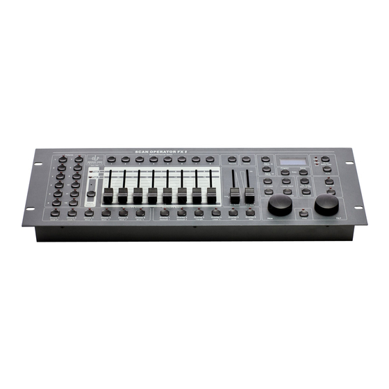
Page 6: Overview
2 Overview 2.1 Front View 6/57... - Page 7 Function-keys to record and delete 9. PROGRAM + With these two keys you change the operation mode of the Setup key Scan Operator FX II 10. Speed/Sensitivity Here you can adjust the automatic … (0,12s – 12m 30s). This Fader/FX Speed...
-
Page 8: Rear View
Manual Go key and learns the timing. The LCD Display then changes between chaser steps and the current bank. 17. Blackout key With the Blackout key you can overwrite the DMX Output with self defined data you configured before. For example all Shutter channels with data “0”. -
Page 9: Installation Into A 19" Rack
2.3 Installation into a 19“ rack The Scan Operator FX II can has been built to be directly installed into a 19” rack. No additional installation material is needed. 9/57... -
Page 10: Dmx Basics
3 DMX Basics To operate the Scan Operator FX II, a basic knowledge about the DMX signal transmission, is necessary. This chapter offers a short introduction to the world of DMX data transmission and addresses to beginners and those who have no, or just a little experience with DMX. -
Page 11: The Conversion To Light
3.3 The conversion to Light Every DMX Fixture has its own committed amount of operating channels for its functions(like movement, brightness, selecting colors and so on), given by the manufacturer. Since every unit receives all DMX channels of the controller, you have to set every fixture to the right start address. -
Page 12: Dmx Channel Assignments
3.4 DMX Channel Assignments The Scan Operator FX II sends 192 DMX channels, which correspond to 12 fixtures with 16 DMX channels per fixture(12*16=192 . The following table lists the first DMX addresses for each fixture: DMX start address, if you start... -
Page 13: Using The Scan Operator Fx Ii
4 Using the Scan Operator FX II 4.1 Overview This DMX controller allows to control up to 12 Fixtures with up to 16 DMX channels each. There are 30 Banks with 8 Scenes per Bank.. Out of these 240 scenes you can build up to 6 chasers with each up to 250 steps. -
Page 14: Easy Mode
channels, turn on the Fade-time function for each channel and alter the assignment of the Pan/Tilt wheels. The Pan/Tilt wheels can be assigned per fixture to one channel (1 to 16), each and can be an alternative Pan/Tilt adjustment opportunity besides of the appropriate channel faders. -
Page 15: Reading The Lcd Display
4.4 Reading the LCD Display The LCD display consists of 2 lines of each 8 signs. The display is intensively used to show the current condition. In a normal condition it always shows the current mode in the first line. In the line below you can find information to the belonging mode. In Play Mode you have the current bank and the current scene shown in the second line. -
Page 16: Programming Scenes
4.6 Programming scenes 4.6.1 Creating a new Scene A scene is an adjustment of all 192 DMX values of different DMX sets including a possible Pan/Tilt effect for each fixture. Up to 240 scenes can be stored. The scenes are subdivided in 30 banks with each 8 scenes. 1. -
Page 17: Editing Scenes
As a memory confirmation you’ll receive the message "Scene Saved". After that, the display will show the current bank and scene. 7. Continue the steps 2-7 until all desired scenes are stored. 8. To leave PROGRAM mode, press the PROGRAM key for 3 seconds. 4.6.2 Editing Scenes 1. -
Page 18: Copying A Scene
4.6.3 Copying a Scene 1. Activate PROGRAM mode (PROGRAM key). 2. Press the BANK UP/DOWN key to call up the desired bank in which the scene that shall be copied is on. 3. Load the scene which you would like to copy by pressing the appropriate scene key once. -
Page 19: Copying A Complete Scene Bank
4.6.5 Copying a complete Scene Bank 1. Activate PROGRAM mode (PROGRAM Key). 2. Press the BANK UP/DOWN key to call up the desired bank you would like to copy. 3. Press the RECORD key. 4. Press the BANK UP/DOWN key until you reached the bank you would like to copy to. -
Page 20: Programming Chasers
4.7 Programming Chasers A Chaser is a program, which calls at maximum of 250 scenes successively. You must have programmed the scenes, from which you "build up" the Chaser, before. Should you change scenes later, the program of the Chaser changes as well. Should a scene in which a chaser is used, be deleted afterward, then the chaser will not load the scene, since it is empty. -
Page 21: Insert A Scene Bank Into A Chaser
4.7.2 Insert a Scene Bank into a Chaser You might copy a whole bank into a Chaser as well. In this case the controller will insert all existing scenes on that bank into the chaser automatically (If the chaser is containing steps already, it will insert the steps at the end). -
Page 22: Change The Editing Position Of A Chaser
4.7.3 Change the editing position of a Chaser Since the functions for inserting a bank and for inserting a step always insert it behind the current step of a chaser, it can be desirably, in particular during the rework of a Chaser, to change the current editing position. -
Page 23: Delete A Step In Chaser
4.7.4 Delete a step in Chaser The deletion of a Chaserstep is only possible in the Chaserstep announcement, since you can choose the step that you want to delete only here. 1. Activate PROGRAM Mode (PROGRAM key). 2. Select the desired Chaser which contains the step that should be deleted. 3. -
Page 24: Resetting The Entire Show Memory
4.8 Resetting the entire Show Memory This function clears and initializes the entire show memory. After the deletion the Memory will be in the following condition: All scenes are deleted All Chaser are deleted All overlay scenes are deleted ... -
Page 25: Blackout Configuration
4.9 Blackout configuration 4.9.1 Setting up the Blackout function You can program the Blackout function freely according to your desires. You can set whether each channel of any fixture will be overridden, and if so, with which value. It is possible to configure the Blackout function so that it only closes the Shutter of all fixtures but the movements and effects continue to run. - Page 26 8. Repeat the steps 3 to 6, in order to configure further Fixtures 9. If the desired Blackout function is provided, then store it by pressing the RECORD key. 10. Afterward press the BLACKOUT key. The procedure corresponds to the sequence, as if you wanted to store a normal scene on the Blackout -Key.
-
Page 27: Resetting The Blackout Function
4.9.2 Resetting the Blackout function With this function you can reset the Blackout to it’s default values. This means that all 192 channels receive the status "on" and are overwritten the value "0". After the deletion of the entire memory this is the case likewise (see above). For setting the Blackout-Scene back you proceed as follows: 1. -
Page 28: Overlay Scenes
4.10 Overlay scenes The Scan Operator FX II offers 6 selective overlay scenes which you can edit freely. These scenes work exactly, like the Blackout function described above, but on a lower priority level: Overlay scenes overwrite selected channels with predefined values in Play Mode. - Page 29 Hint: By pressing the "releases" key you can set all channels back to the value 0. Also all channels will be switched to "off" again, so that you can begin to program a new overlay from ground up. 7. You can set the desired values wit the faders. You might also set the values of the channels, which will not be overwritten (status "off").
-
Page 30: Deleting Overlay Scenes
4.10.2 Deleting Overlay Scenes For the deletion of an overlay scene you proceed as follows: 1. Activate PROGRAM mode (PROGRAM key) 2. Select bank 31 and/or the position, where the bank 31 would be. The display will show "overlay". 3. Keep the DELETE key pressed and simultaneously press the key of the overlay scene, which you would like to delete. -
Page 31: Effect Patterns
4.11.1 Effect Patterns The Scan Operator FX II offers 12 different effect patterns for Pan/Tilt: "Circle CW" produces a circle in clockwise direction "Circle CCW" produces a circle against the clockwise direction "sine" produces a sinusoidal movement. Altogether 4 different sine movements stand to the selection, which differ in their direction: ... -
Page 32: The "Randomize" Function
Renewed operation changes the wave in such a way that each second lamp makes one 180° shifted movement first (allocation in straight and oddly selected lamps). After a third pressing of the key, the wave will be reversed. A fourth pressing of the key returns again to the starting situation of the starting angles. Example : You select all Fixtures in the Program mode and open the effect editor. -
Page 33: Creating An Effect
the effect "Wild" and select any size, and a slow speed. All 12 fixtures will implement synchronously the "Wild" movement now. After pressing the Randomize key the starting angles for pan and Tilt become randomized. This leads to it that all fixtures move, however each lamp drives another way. -
Page 34: Deleting An Effect
the "FX CLEAR" key. 11. As soon as you finish the providing of the effects, leave the effect editor again by pressing the "FX editor" key. You can now, as usual, store the DMX effect into a scene. 12. If you finished the storing of the scenes, then you leave the PROGRAM mode again pressing the PROGRAM key for 3 seconds. -
Page 35: Configuring Fade Time Function
4.12 Configuring Fade time function As already described above, it is possible to define channels that are able to “crossfade” with the time given by the Fade time fader. The controller generates intermediate steps, which automatically slow the movement down. It is meaningful thereby that these intermediate steps are only to be generated for movement and possible Dimmer channels. -
Page 36: Resetting The Fade Time Configuration
4.12.2 Resetting the Fade Time Configuration In order to reset the Fade time function for all channels, you proceed as follows: 1. Activate Setup mode (SETUP key). 2. Now select “Fadetime". In the menu of the Setup mode. 3. Press the DELETE key. For confirmation you will receive the message "Fadetime RESET". -
Page 37: Inverting Channels
4.13 Inverting channels Each of the 192 channels can be inverted individually. Inverting takes place in the Setup menu and is deleted likewise with the deletion of the entire memory. 4.13.1 Configuring Inverted Channels To toggle the inversion of one or more channels you proceed as follows: 1. -
Page 38: Resetting All Inverted Channels
4.13.2 Resetting all Inverted Channels In order to reset all inverted channels, proceed as follows: 1. Activate Setup mode (SETUP key). 2. Now select "Invert" in the menu of Setup mode 3. Press the DELETE key. For confirmation you will receive the message "Invert RESET". Important: The changes are not automatically durably stored but they are directly active. -
Page 39: Pan And Tilt Encoder
4.14 Pan and Tilt Encoder You can assign the Pan/Tilt Encoder wheels for each Fixture to one of the 16 DMX of channels in each case. They serve as additional input mode for Pan and Tilt values beside the appropriate DMX faders. In addition the effect generator also falls back to the channels adjusted here, if Pan/Tilt effects are produced. -
Page 40: Using The Pan And Tilt Encoder Wheel
4.14.2 Using the Pan and Tilt Encoder wheel You can use the pan and Tilt Encoder of wheels both in the Program and in the Play mode. The Encoder wheels change the accordingly configured Pan/Tilt DMX channels in each case. The Fine button regulates if, whether per click on the Pan/Tilt wheels, either to 1 DMX step (Fine On) or 8 DMX steps (Fine Off) are made. -
Page 41: Autostart Function
4.16 Autostart function The Scan Operator FX II offers an Autostart function, which repairs the stored playback condition by switching the set on and off. In addition the possibility exists that when switching the set on, the Desklock is activated automatically. -
Page 42: Storing Current Playback Condition As A Autostart Condition
Therefore it is necessary that you confirm the changes for durable storing once with the RECORD or the SETUP key. 4. Press the SETUP key for 3 seconds, to leave the Setup mode again. 4.16.3 Storing current playback condition as a autostart condition If you activate the Autostart mode, then you can store the current playback condition as an Autostart condition. -
Page 43: Running Scene Banks (Play Mode)
4.17 Running Scene Banks (Play mode) 4.17.1 Running a Scene manually 1. After turning the CONTROLLER on it is automatically in the Play mode. 2. Make sure that the manual trigger mode is selected (see the “Manual LED” to the right of the display). 3. -
Page 44: Running A Scene Bank With Auto Trigger
4.17.2 Running a Scene Bank with Auto Trigger This function makes it possible to let a bank of scenes or a Chaser run automatically in a loop. 1. Press the AUTO key to call up this function. The auto trigger timing that has been used last is restored automatically and indicated in the display. -
Page 45: Running A Scene Bank With Music Trigger
4.17.3 Running a Scene Bank with Music Trigger 1. Press the MUSIC/BANKCOPY key to activate the music trigger. The music sensitivity that has been used last is automatically restored and indicated in the display. The MUSIC LED lights up. 2. Use the BANK UP/DOWN keys to select the desired bank. The occupied scenes of this bank will be started one after another controlled by the music input. -
Page 46: Manual Overwriting Channels By Using The Faders (Play Mode)
4.18 Manual overwriting channels by using the Faders (Play mode) You can overwrite Play mode channels by means of the Fader. This function is meant, to do smaller changes in live performance. In order to overwrite channels, you proceed as follows: 1. -
Page 47: Running A Chaser (Play Mode)
4.19 Running a Chaser (Play mode) Hint: You have to have programmed the Chaser before in order to call it up. Empty chasers can not be started. 4.19.1 Running a Chaser Manually 1. Select the desired Chaser 1-6. By renewed pressing of the chaser key you deactivate it again. -
Page 48: Running A Chaser With Music Trigger
4.19.3 Running a Chaser with Music Trigger 1. Select the desired Chaser of 1-6. By renewed pressing of the Chaser key you deactivate it again. Hint: Several Chasers can be selected at the same time. These run off then successively. 1. -
Page 49: Midi Control
4.21 MIDI Control This controller can receive MIDI command in Playback Mode to trigger different memories and playback options. You can choose between 2 different MIDI modes: MIDI Synthesizer Mode Here the individual scenes of the first 15 banks are directly accessible via MIDI. In addition the Chaser and the Blackout function can be controlled. -
Page 50: The Midi Keyboard Mode
4.21.1 The MIDI keyboard mode This mode is optimized, to use the Scan Operator in live environments with a 49 keys MIDI keyboard. The 30 banks as well as the 6 Chaser are directly callable as programs. You can also control the Blackout and the Freeze function as well as the functions for trigger setup. -
Page 51: Synthesizer Mode
4.21.2 Synthesizer Mode Here the individual scenes of the first 15 banks are directly accessible by MIDI. In addition the Chaser and the Blackout function can be controlled. MIDI Note Funktion BANK 1 Scene 1 Bank 1 on/off Scene 2 Bank 1 on /off Scene 3 Bank 1 on /off Scene 4 Bank 1 on /off Scene 5 Bank 1 on /off... -
Page 52: Selecting Midi Channel And Midi Mode
4.21.3 Selecting MIDI channel and MIDI mode 1. To arrive at the Setup mode, press the SETUP key for 3 seconds. You are directly in the MIDI point of menu. 2. With the Pan Encoder wheel can now adjust the MIDI channel. 3. -
Page 53: Easy Mode
4.22 Easy Mode The EASY mode serves for fast tests of DMX fixtures or as additional Faderdesk for larger DMX Desks, which for which a DMX Faderunit is sense full. Here 12 Fixtures with 10 channels each are used. The values of the channels are specified over the 10 Faders of the set (including Fade time and speed). -
Page 54: Copying The Show Data Between 2 Scan Operator Fx Ii
4.23 Copying the Show Data between 2 Scan Operator FX II It is possible to transfer all memory contents of one Scan Operator FX II to another one. Use the following steps to transfer the memory: 1. Both controllers are switched Off 2. -
Page 55: Editing The Power-On Logo
The Logo is not deleted, if you use the function that clears the entire show memory! 4.26 Showing the Software Version If you keep the MUSIC/BANK COPY button pressed when switching the Unit on, the Software Version of your Scan Operator FX II appears in the display. 55/57... -
Page 56: Technical Specifications
5 Technical specifications 5.1 general data DC Input ……..................DC 9V, 500mA DMX Exit ...................3 pol, female XLR MIDI Signal ..................5 pol, DIN Standard Audio Control ................. Built-In Microphone Dimensions ..................482 x 176 x 73 mm Weight .........................2,5 Kg 5.2 DMX Parameter Channels sent......................192 Break.............. - Page 57 57/57...
Need help?
Do you have a question about the SCAN OPERATOR FX II and is the answer not in the manual?
Questions and answers