
Related Manuals for GLP IMPRESSION 120 RZ WWC


Summary of Contents for GLP IMPRESSION 120 RZ WWC
- Page 1 & & & from software version 1.00/03 (Instruction version 1.14) e-mail: service@glp.de Internet: http://www.glp.de...
- Page 2 & & & This manual serves for both systems the C as well as the . The two systems differ from each other only by the number of cold- respectively warm- white LEDs. WWC version: 42x LEDs cold white, 78x LEDs warm white CCW version: 78x LEDs cold white, 42x LEDs warm white Notes: German Light Products GmbH...
-
Page 3: Table Of Contents
& & & Table of content Description of Device....................4 1.1 Safety Instructions .................... 5 Preparation and Installation ................... 6 2.1 Mounting ......................6 2.1.1 Mounting on the floor (upright) ............. 7 2.1.2 Mounting in hanging position (head down) .......... 8 2.1.3 Mounting in a sideway position ............ -
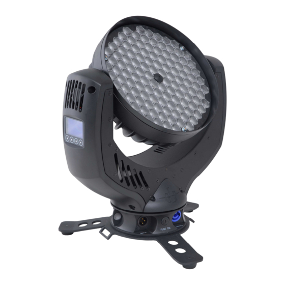
Page 4: Description Of Device
& & & 1 Description of Device 1. Moving head (actively and passively cooled) 2. Arm with various cooling vents 3. LCD-Display/Menu (data entry) 4. Base with various connectors and Camlock mounting system b a se sid e 1 5. Power On/Off 6. -
Page 5: Safety Instructions
& & & Safety Instructions N is an advanced technology product. To guarantee smooth operation, it is necessary to follow the following instructions. The manufacturer of this device will not take responsibility of damages through any disregard of the information in this user manual. -
Page 6: Preparation And Installation
10. Repair-, maintenance- and installation work should only be performed by qualified or GLP certified staff. You need to pay attention to the common rules of technology that are not explicit mentioned in this manual. 11. Use only original spare parts. Any structural modification on the system will terminate all warranty claims. -
Page 7: Mounting On The Floor (Upright)
& & & For the various mounting positions of the N (standing on the floor, sideways or hanging) different accessories kits are available. Using any required kits, along with the standard mounting connectors on the base of the fixture, will ensure a safe and firm installation. 1x M10 (length max.16mm) 2x Camlock... -
Page 8: Mounting In Hanging Position (Head Down)
To operate the N in a sideways position, please use an additional mounting bar, available from GLP or one of their agents.. This mounting bar is fixed via the two camlock quick-release connectors. Two half-couplers or clamps are then used to hang the mounting bar. This technique is necessary to cope with the additional torque in this mounting position. -
Page 9: Securing The Device
& & & 2x 90° Half-coupler (clamp) 1 Half-coupler (clamp) 2 without mounting bar 2.2 Securing the Device Regardless of the mounting method of the N you'll have to use a secondary safety wire. This safety wire can be attached to the fixture by threading it through one of the two holes provided on the base of the fixture. -
Page 10: Dmx
& & & 2.3.2 DMX USITT DMX-512 Standard input/output with 3 pole connectors. 3 pole: Pin 1 = [Ground] / Pin 2 = [-] / Pin 3 = [+] The DMX- Addressing starts at DMX- Address [001]. 3 The Menu Field You’ll find the control board on the side of the arm. - Page 11 & & & Clear Erase EEPROM memory EEPROM Diagnose Diagnose functions Pos Feed Internal data and function diagnose Pan Delta Anz Ti0- Internal data and function diagnose Int-Err Show the present PFC voltage Voltage Pos Feed Internal data and function diagnose Tilt Delta Temperature Indicates the arm temperature...
-
Page 12: Dmx Channel Selection (Dmx Protocol)
& & & High- Fixture works in "High Resolution" mode see also Resolution section 4 Reverse Pan Selects Inverse Pan, on or off Reverse Tilt SelectsInverse Tilt on or off Reset RESET all functions 4 DMX Channel Selection (DMX Protocol) Normal-Mode 12 DMX channels Channel Function... - Page 13 & & & Channel Function Time and Value 180° 28..29 1C..1D 11,2 270° 30..31 1E..1F TILT size / phase see also PAN 32..63 20..3F 13..25 PAN / TILT size / phase see also PAN 64..95 40..5F 26..37 PAN / TILT (inverse) size / phase see also PAN 96..127 60..7F...
- Page 14 & & & High Resolution (Extended) -Mode 12 DMX Channels Channel Function Time and Value 1) PAN- 0 .. 660° 3,2 s 0..255 00..FF 0..100 coarse 2) PAN-fine High- Pos ... High- Pos + 2,6° (16 Bit) 0..255 00. .FF 0..100 3) Tilt- 0 ..
-
Page 15: Maintaining And Cleaning The I M P R E S S I O N
& & & In addition, all standard settings will be loaded (DMX start address [001], Normal Mode). c) Standard Mode (Hold down the ENTER- button during power ON) After switching on the fixture, the DMX start address will be set to [001]. All other settings will remain unchanged. -
Page 16: Technical Specifications
& & & Maintenance Task Interval weekly soft brush /lint-free cloth Cleaning LED lenses and optical system Cleaning of fans and air channels monthly vacuum cleaner, airbrush, etc. Attention: • Never let optical parts come into contact with oil or fat. •... -
Page 17: Index
& & & Index Mounting in sidewise Position ......8 Mounting on the Floor ........7 Angel of reflected beam ......... 16 Normal-Mode ..........12 BGV C1............6 Optical parts ..........16 CCW version ..........2 Circumference ..........15 Cleaning............15 Pan- Movement .......... - Page 18 & & & German Light Products GmbH (Instruction version 1.14) / from software version 1.00/03)
Need help?
Do you have a question about the IMPRESSION 120 RZ WWC and is the answer not in the manual?
Questions and answers