
Related Manuals for GE Ultrasonic USM Go


Summary of Contents for GE Ultrasonic USM Go
- Page 1 Sensing & Inspection Technologies Ultrasonic USM Go Operator’s Manual P/N 1259801 Rev. 1 July 2009...
- Page 3 USM Go Ultrasonic Flaw Detector Operator’s Manual P/N 1259801 Rev. 1 July 2009 GESensingInspection.com ©2009 General Electric Company. All rights reserved. Technical content subject to change without notice.
- Page 4 [no content intended for this page - proceed to next page]...
-
Page 5: Table Of Contents
Contents Chapter 1. General Information 1.1 Supplying Power to the Instrument ................2 1.2 Powering the Instrument ON and OFF . - Page 6 Contents Chapter 2. Instrument Setup 2.1 Display Screen and Keypad Features ................17 2.2 The Menu System .
- Page 7 Contents 2.5 Adjusting the A-Scan ..................51 2.5.1 Setting the A-Scan Range .
- Page 8 Contents 3.3 Displaying Measured Results ................. . 75 3.4 Locking the Gain Toggle and the Joystick .
- Page 9 Contents 3.13DGS Evaluation Mode ..................92 3.13.1 Specifying a Probe and Preparing to Record the Reference Echo .
- Page 10 Contents 4.2 Working With Data Set Files ................. 115 4.2.1 Storing a New Data Set File .
- Page 11 Contents 5.3 Creating the Data Recorder File ................130 5.4 Viewing the Data Recorder File .
- Page 12 Contents B.2 Battery Disposal ................... 147 B.2.1 What do the Markings Mean? .
-
Page 13: Safety Information
Preface Safety Information Before powering up or operating this instrument, the safety information in this section should be read carefully. This Operator’s Manual should be stored in a safe place for reference. IMPORTANT: This instrument is to be used only for testing materials in an industrial environment. Any use for medical applications or any other purpose is not permitted. - Page 14 Preface Important Ultrasonic Testing Guidelines Please read the information in this section before using your instrument. It is important that you understand and observe this information to avoid any operator errors that might lead to false test results. Such false results could result in personal injuries or property damage. Using Ultrasonic Test Equipment This Operator’s Manual contains essential information on how to operate your test equipment.
- Page 15 Preface Operator Training The operation of an ultrasonic test device requires proper training in ultrasonic testing methods. Proper training comprises adequate knowledge of: • The theory of sound propagation • The effects of sound velocity in the test material • The behavior of the sound waves at interfaces between different materials •...
- Page 16 Preface Test Object Material Effects If the material of the test object is not homogeneous, the sound waves may propagate at different velocities in different parts of the test object. An average sound velocity should then be used for the range calibration. This is achieved by using a reference block with a sound velocity equal to the average sound velocity of the test object.
-
Page 17: Limited Warranty
Preface Limited Warranty For a period of two (2) years from the date of purchase, we warrant that the instrument will be free of any claim of ownership by third parties, (ii) when new, be free from defects in material and workmanship and perform in accordance with the Product’s specifications under normal use and service for the applicable warranty period following the date of sale. - Page 18 Preface [no content intended for this page - proceed to next page] USM Go Operator’s Manual...
-
Page 19: Chapter 1. General Information
Chapter 1. General Information Chapter 1. General Information The USM Go is a portable ultrasonic flaw detector. In addition to its light-weight design, the USM Go includes a clean and simple user interface and a large, easy-to-read color WVGA (800x480) display. When operating in Acquire Mode, the instrument provides ultrasonic flaw detection and thickness measurements. -
Page 20: Supplying Power To The Instrument
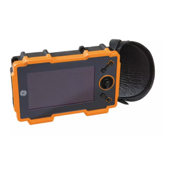
Chapter 1. General Information 1.1 Supplying Power to the Instrument 1/4-Turn Screw (CW to close, CCW to open) Accessory Mounting Screw Slot Power ON/OFF Receive Probe Connection Pulse/Transmit Probe Connection Battery Charger Connection 1/4-Turn Screw (CW to close, CCW to open) Figure 1: Rear and Side Views of the USM Go Case USM Go Operator’s Manual... - Page 21 Chapter 1. General Information 1.1 Supplying Power to the Instrument (cont.) The USM Go can be powered in either of two ways (see Figure 1 on page 2): • A lithium battery pack that is installed in a compartment on the rear of the case, or •...
-
Page 22: Powering The Instrument On And Off
Chapter 1. General Information 1.1 Supplying Power to the Instrument (cont.) When the AC adapter is connected to the instrument, the icon in the upper right corner of the display indicates the percentage of full-charge of the battery pack. When removing the battery pack to install a charged spare, the instrument will automatically turn OFF if the AC adapter is not connected to the instrument. - Page 23 Chapter 1. General Information 1.3 Using the Keypad (cont.) Battery Indicator Gain Toggle Joystick Function Toggle Display Screen Figure 2: Front Panel of the USM Go USM Go Operator’s Manual...
-
Page 24: Instrument Orientation
Chapter 1. General Information 1.3.1 Instrument Orientation One of the innovative features of the USM Go is the user option to quickly and easily rotate the instrument 180° to accommodate either right-hand or left-hand operation. During this process, the display image is also rotated to allow proper viewing. Figure 3 below shows the instrument in both orientations. -
Page 25: Keypad Components
Chapter 1. General Information 1.3.2 Keypad Components The USM Go keypad includes the following items (see Figure 2 on page 5): • Center-press joystick ( ): The joystick may be moved either “left or right” or “up or down.” In addition, the center of the joystick may either be “pressed”... -
Page 26: Joystick Functions
Chapter 1. General Information 1.3.3 Joystick Functions The effects of the joystick actions described on the previous page are as follows: Joystick Center Press: • When in Acquire Mode, a single press and release ( ) toggles the A-Scan display between standard size and full screen mode. •... -
Page 27: Multi-Key Functions
Chapter 1. General Information 1.3.4 Multi-Key Functions Note: All multi-key functions are defined with the instrument in the left-hand orientation (see the left side of Figure 3 on page 6). • Power button + Function 2 button + Gain DOWN button Pressing and holding these three buttons simultaneously causes the instrument to initiate a software upgrade. -
Page 28: Using The Display
Chapter 1. General Information 1.4 Using the Display Typical displays for the USM Go Acquire Mode and Setup Mode menus are illustrated in Figure 4 below. See the following pages for step-by-step instructions on accessing these menus. Gate Results Gain Window Battery Indicator Menu Title Grid Menu Bar... -
Page 29: Accessing The Acquire Mode Menu
Chapter 1. General Information 1.4.1 Accessing the Acquire Mode Menu To access the Acquire Mode menu, refer to the left side of Figure 4 on page 10 while completing the following steps: Move the joystick left or right ( ) until the desired menu is highlighted on the menu bar. The function bar automatically shows the parameters available in the highlighted menu. -
Page 30: Accessing The Setup Mode Menu
Chapter 1. General Information 1.4.2 Accessing the Setup Mode Menu To access the Setup Mode menu, refer to the right side of Figure 4 on page 10 while completing the following steps: Press and hold the center of the joystick ( ) to toggle between Acquire Mode and Setup Mode. -
Page 31: Using The Sd Slot, Usb Connector & I/O Connector
Chapter 1. General Information 1.5 Using the SD Slot, USB Connector & I/O Connector The USM Go uses a standard SD memory card for storing data set files and reports (see “The FILES Menu” on page 114) and for loading an instrument software upgrade (see “Activating Instrument Upgrades”... -
Page 32: Removing The Sd Card
Chapter 1. General Information 1.5.1 Removing the SD Card To remove the SD card from its slot, proceed as follows: Access the SD card slot by pushing on the cover in the direction of the arrow and lifting the hinged cover. Press down of the SD card with your finger and then remove your finger quickly. -
Page 33: Connecting The Usb Port
Chapter 1. General Information 1.5.3 Connecting the USB Port The connector closest to the hinge of the top compartment cover (see Figure 5 on page 13) is a Micro USB port. If you use a standard USB cable to connect the USM Go to a PC (no special drivers are required), the installed SD card will be added to the list of active drives on the PC. -
Page 34: Connecting The I/O Port
Chapter 1. General Information 1.5.4 Connecting the I/O Port The connector furthest from the hinge of the top compartment cover (see Figure 5 on page 13) is an I/O port. This port serves a dual role: • Serial port pins - these are used strictly for factory service diagnostics. •... -
Page 35: Chapter 2. Instrument Setup
Chapter 2. Instrument Setup Chapter 2. Instrument Setup 2.1 Display Screen and Keypad Features The USM Go user interface has been designed for clarity and ease of use. Figure 6 below show the complete set of icons that may appear in the icon area of the screen, and Figure 7 on page 18 shows the major components of the display and the keypad. - Page 36 Chapter 2. Instrument Setup 2.1 Display Screen Features (cont.) Reading 4 Gain Level Reading 3 Gain Toggle Reading 1 Reading 2 Battery Level Icon Area Large Reading Joystick Reading 6 Reading 5 Function 1 Function 2 Function Toggle ACQUIRE Menu Bar Figure 7: Display Screen Features USM Go Operator’s Manual...
-
Page 37: The Menu System
Chapter 2. Instrument Setup 2.2 The Menu System The USM Go menu system, as shown in Figure 8 on page 20, allows the operator to select and adjust various instrument features and settings. It includes: • Acquire Menu: Consists of several submenus used to calibrate the instrument prior to a test, configure the instrument during a test, select the pulser and receiver characteristics, and configure the gates. -
Page 38: Setup Menu
Chapter 2. Instrument Setup 2.2 The Menu System (cont.) ACQUIRE MENU range voltage frequency gate a start gate a start gate b start SELECTED probe delay width rectify s-ref1 gate a width gate b width EVALUATION velocity damping dual s-ref2 a threshold b threshold MODE... - Page 39 Chapter 2. Instrument Setup 2.2 The Menu System (cont.) EVALUATION MODE MENUS AVAILABLE DAC/TCG dB REF AWS D1.1 JISDAC gate A start dgs mode mode A indication gate A start auto80 dgs curve reference B reference auto80 record probe # record C attenuation record...
-
Page 40: Initial Setup
Chapter 2. Instrument Setup 2.3 Initial Setup In this section, you’ll learn how to configure the USM Go display and operating features. Follow these procedures to turn the instrument ON and make initial adjustments to the control settings. Because the instrument can be set to save the control settings when it is turned OFF and restore them when it is turned back ON, you won’t have to repeat these adjustments unless a change is required. - Page 41 Chapter 2. Instrument Setup 2.3.1 Language, Units of Measurement, Date, and Time (cont.) RANGE FREQUENCY LANGUAGE COLOR PROBE DELAY VOLTAGE RECTIFY UNITS DATE GRID VELOCITY DAMPING DUAL DECIMAL TIME A-SCAN COLOR DISPLAY DELAY PRF MODE REJECT DATE FORMAT ORIENTATION BRIGHTNESS RANGE PULSER RECEIVER...
- Page 42 Chapter 2. Instrument Setup 2.3.1a Setting the Acquire Mode Language (SETUP-CONFIG1-LANGUAGE) In the SETUP menu, activate the CONFIG1 submenu using the joystick ( ). Several functions are displayed on the screen. Use the joystick ( ) to select the LANGUAGE function, then press the center of the joystick ( ) to activate the function.
- Page 43 Chapter 2. Instrument Setup 2.3.1b Setting the Units of Measurement (SETUP-CONFIG1-UNITS) In the SETUP menu, activate the CONFIG1 submenu using the joystick ( ). Several functions are displayed on the screen. Use the joystick ( ) to select the function titled UNITS, then press the center of the joystick ( ) to activate the function.
- Page 44 Chapter 2. Instrument Setup 2.3.1c Setting the Decimal Convention (SETUP-CONFIG1-DECIMAL) In the SETUP menu, activate the CONFIG1 submenu using the joystick ( ). Several functions are displayed on the screen. Use the joystick ( ) to select the function titled DECIMAL, then press the center of the joystick ( ) to activate the function.
- Page 45 Chapter 2. Instrument Setup 2.3.1d Setting the Date and Time Formats (SETUP-CONFIG1-DATE FORMAT) In the SETUP menu, activate the CONFIG1 submenu using the joystick ( ). Several functions are displayed on the screen. Use the joystick ( ) to select the function titled DATE FORMAT, then press the center of the joystick ( ) to activate the function.
- Page 46 Chapter 2. Instrument Setup 2.3.1e Setting the Date (SETUP-CONFIG1-DATE) In the SETUP menu, activate the CONFIG1 submenu using the joystick ( ). Several functions are displayed on the screen. Use the joystick ( ) to select the function titled DATE, then press the center of the joystick ( ) to activate the function.
- Page 47 Chapter 2. Instrument Setup 2.3.1f Setting the Time (SETUP-CONFIG1-TIME) In the SETUP menu, activate the CONFIG1 submenu using the joystick ( ). Several functions are displayed on the screen. Use the joystick ( ) to select the function titled TIME, then press the center of the joystick ( ) to activate the function.
- Page 48 Chapter 2. Instrument Setup 2.3.1g Setting Left-Hand or Right-Hand Orientation (SETUP-CONFIG1-ORIENTATION) In the SETUP menu, activate the CONFIG1 submenu using the joystick ( ). Several functions are displayed on the screen. Use the joystick ( ) to select the function titled ORIENTATION, then press the center of the joystick ( ) to activate the function.
-
Page 49: Display Appearance
Chapter 2. Instrument Setup 2.3.2 Display Appearance Follow the procedures in this section to adjust the display appearance. The adjustments require access to the CONFIG1 submenu, which is accessed from the SETUP menu (see Figure 10 on page 23). 2.3.2a Setting the Display Color (SETUP-CONFIG1-COLOR) In the SETUP menu, activate the CONFIG1 submenu using the joystick ( ). - Page 50 Chapter 2. Instrument Setup 2.3.2b Selecting a Display Grid (SETUP-CONFIG1-GRID) In the SETUP menu, activate the CONFIG1 submenu using the joystick ( ). Several functions are displayed on the screen. Use the joystick ( ) to select the function titled GRID, then press the center of the joystick ( ) to activate the function.
- Page 51 Chapter 2. Instrument Setup 2.3.2c Setting the A-Scan Color (SETUP-CONFIG1-ASCAN COLOR) In the SETUP menu, activate the CONFIG1 submenu using the joystick ( ). Several functions are displayed on the screen. Use the joystick ( ) to select the function titled ASCAN COLOR, then press the center of the joystick ( ) to activate the function.
- Page 52 Chapter 2. Instrument Setup 2.3.2d Setting the Display Brightness (SETUP-CONFIG1-BRIGHTNES) In the SETUP menu, activate the CONFIG1 submenu using the joystick ( ). Several functions are displayed on the screen. Use the joystick ( ) to select the function titled BRIGHTNESS, then press the center of the joystick ( ) to activate the function.
-
Page 53: Defining Function Toggle Actions
Chapter 2. Instrument Setup 2.3.3 Defining Function Toggle Actions The user can specify a desired action to occur when either end of the Function Toggle ( ) is pressed or pressed-and-held. The user-specified function action is ignored, however, whenever a parameter is selected and its value is being edited. In the SETUP menu, activate the CONFIG2 submenu using the joystick ( ). - Page 54 Chapter 2. Instrument Setup 2.3.3 Defining Function Toggle Actions (cont.) To change the lower parameter, press the function toggle to scroll through the options. The available options include: NONE – no action is assigned. • FREEZE – Freezes the A-Scan and displays the Freeze icon (see Figure 6 on page 17) in the status bar. •...
-
Page 55: Installing A Probe
Chapter 2. Instrument Setup 2.4 Installing a Probe Follow the instructions in this section to install a probe on your USM Go. Receive 2.4.1 Connecting the Probe Probe When connecting a probe to the instrument, the following steps must be taken: •... -
Page 56: Configuring The Instrument
Chapter 2. Instrument Setup 2.4.2 Configuring the Instrument Three instrument settings are directly dependent on the type of probe installed. These settings must be adjusted any time a probe of a different type is installed, by following the instructions in the following sections. 2.4.2a Selecting the Probe Type (RECEIVER-DUAL) - Page 57 Chapter 2. Instrument Setup 2.4.2b Specifying the Probe Frequency ( RECEIVER-FREQUENCY) In the ACQUIRE menu, activate the RECEIVER submenu using the joystick ( Use the joystick ( ) to select the function titled FREQUENCY. To change the specified frequency, move the joystick ( ) or press the function toggle.
- Page 58 Chapter 2. Instrument Setup 2.4.2c Changing Damping Level to modify the Signal to Noise Ratio (PULSER-DAMPING) In the ACQUIRE menu, activate the PULSER submenu using the joystick ( Use the joystick ( ) to select the function titled DAMPING. To change the specified damping level and optimize the A-Scan signal appearance, move the joystick ( ) or press the function toggle.
-
Page 59: Adjusting The Pulser Repetition Frequency (Prf)
Chapter 2. Instrument Setup 2.4.3 Adjusting the Pulser Repetition Frequency (PRF) The Pulser fires at a frequency which can be set either automatically or manually. To set the PRF mode and frequency level: In the ACQUIRE menu, activate the PULSER submenu using the joystick ( ) to select the function titled PRF MODE. -
Page 60: Setting The Pulser Voltage
Chapter 2. Instrument Setup 2.4.3 Adjusting the Pulser Repetition Frequency (PRF) (cont.) If PRF MODE is set to AUTO HIGH, AUTO MED or AUTO LOW, the automatically calculated value is displayed in the function box. If you selected the MANUAL option, you may now adjust the PRF value by moving the joystick left or right ( Note: The PRF setting may be limited based on the user-selected pulser voltage setting. -
Page 61: Selecting The Pulser Type (Optional)
Chapter 2. Instrument Setup 2.4.5 Selecting the Pulser Type (OPTIONAL) The standard pulser shape is a spike, and there is also an optional square pulser shape available. If the PULSER TYPE option is activated, choose between the spike and square options as follows: In the SETUP menu, activate the CONFIG2 submenu using the joystick ( Use the joystick ( ) to select the function titled PULSER TYPE. -
Page 62: Selecting The Pulser Width (Optional)
Chapter 2. Instrument Setup 2.4.6 Selecting the Pulser Width (OPTIONAL) The standard pulser shape is a spike, and there is also an optional square pulser shape available. If the PULSER TYPE option is activated and a SQUARE wave is chosen, the user may specify the time-based width of the pulser. The pulser width generally varies from 30 to 500 nanoseconds. - Page 63 Chapter 2. Instrument Setup 2.4.6 Selecting the Pulser Width (OPTIONAL) (cont.) To set a pulser width: In the ACQUIRE menu, activate the PULSER submenu using the joystick ( ) to select the function titled WIDTH, which is only available if the PULSER TYPE function is set to square. Use the joystick ( Press the function toggle or move the joystick ( ) to set the width of the pulser.
-
Page 64: Using The Phantom Prf Feature
Chapter 2. Instrument Setup 2.4.7 Using the Phantom PRF Feature When activated, this diagnostic feature varies the PRF to identify any wrap-around signals, which are phantom echoes caused by a PRF setting that is too high. When this feature is activated, the time-based position of the phantom echoes varies while the true echoes remain stationary on the display screen. -
Page 65: Selecting A Rectification Mode
Chapter 2. Instrument Setup 2.4.8 Selecting a Rectification Mode Rectification effects the orientation of the A-scan on the display screen. The A-scan represents the sound pulse (i.e. echo) that is returned to the instrument from the material being tested. The series of echoes looks like the Radio Frequency (RF) signal shown in Figure 12 below. Note that the RF signal has both a negative component below the axis and a positive component above the axis. - Page 66 Chapter 2. Instrument Setup 2.4.8 Selecting a Rectification Mode (cont.) • Positive Half Rectification means that only the upper (i.e. positive) half of the RF signal is displayed. • Negative Half Rectification means that only the bottom (i.e. negative) half of the RF signal is displayed (see Figure 12 on page 47). Note that although only the negative half of the RF signal is displayed, it is shown in the same orientation as a positive component to simplify viewing.
- Page 67 Chapter 2. Instrument Setup 2.4.8 Selecting a Rectification Mode (cont.) In the ACQUIRE menu, activate the RECEIVER submenu using the joystick ( Use the joystick ( ) to select the function titled RECTIFY. The following options are available: NEG HALFWAVE - Shows the negative component of the RF signal but displays it in a positive orientation. •...
-
Page 68: Setting The A-Scan Reject Level
Chapter 2. Instrument Setup 2.4.9 Setting the A-Scan REJECT Level A portion of the A-Scan can be omitted from the display screen, by defining the percentage of the full-screen height you wish to omit. To set a reject percentage: In the ACQUIRE menu, activate the RECEIVER submenu using the joystick ( Use the joystick ( ) to select the function titled REJECT. -
Page 69: Adjusting The A-Scan
Chapter 2. Instrument Setup 2.5 Adjusting the A-Scan To configure the USM Go A-Scan, follow the instructions in this section. 2.5.1 Setting the A-Scan Range Calibration of the USM Go requires the use of two calibrated standards. These standards must be of different thicknesses, and they must be made of the same material as the test piece. - Page 70 Chapter 2. Instrument Setup 2.5.1 Setting the A-Scan Range (cont.) To set the A-Scan range: In the ACQUIRE menu, activate the RANGE submenu using the joystick ( ) to select the function titled RANGE, which has both coarse and fine adjustment modes. Coarse adjustments Use the joystick ( are made with the function toggle, while fine adjustments are made with the joystick.
-
Page 71: Setting The Display Delay
Chapter 2. Instrument Setup 2.5.2 Setting the Display Delay The display delay function shifts the displayed A-Scan to the left or the right in the viewing window. To set the display delay: In the ACQUIRE menu, activate the RANGE submenu using the joystick ( ) to select the function titled DISPLAY DELAY. -
Page 72: Calibrating The Instrument
Chapter 2. Instrument Setup 2.6 Calibrating the Instrument To calibrate the USM Go, follow the instructions in this section. 2.6.1 Pre-Calibration Check List To improve the accuracy and quality of your calibration, be sure that the following steps have been taken before beginning the calibration: •... -
Page 73: Using Autocal
Chapter 2. Instrument Setup 2.6.2 Using AUTOCAL Note: While following the instructions in this section, refer to Figure 14 on page 56. In the ACQUIRE menu, activate the AUTOCAL submenu using the joystick ( ) to select the function titled S-REF1. Then, press the function toggle or move the joystick ( Use the joystick ( ) to change the value to match the thickness of the thinner calibration standard. - Page 74 Chapter 2. Instrument Setup 2.6.2 Using AUTOCAL (cont.) Figure 14: Auto Calibration Procedures USM Go Operator’s Manual...
- Page 75 Chapter 2. Instrument Setup 2.6.2 Using AUTOCAL (cont.) Note: During the following steps, pressing both buttons on the Gain Toggle simultaneously activates the AUTO80 function. ) to select the function titled RECORD. The value in the function box changes from “OFF” to “S-REF1?”. Use the joystick ( While maintaining the signal in Gate A, move the joystick right or left ( ) to record the reference echo.
-
Page 76: Checking The Calibration Results
Chapter 2. Instrument Setup 2.6.3 Checking the Calibration Results Following the calibration procedure, the calculated acoustical velocity and probe delay are displayed. To view these calculated values: In the ACQUIRE menu, activate the RANGE submenu using the joystick ( Press the function toggle or move the joystick ( ) to view the following selections: PROBE DELAY - The adjustment made as a result of the AUTOCAL (zeroing) procedure is shown. -
Page 77: Using The Calibration Reminder Alarm
Chapter 2. Instrument Setup 2.7 Using the Calibration Reminder Alarm The USM Go incorporates a timed alarm feature that causes an icon to appear on user-defined input intervals between 0.5 and 4.0 hours. To use this alarm: In the SETUP menu, activate the CONFIG2 submenu using the joystick ( Use the joystick ( ) to select the function titled CAL REMINDER, then press the center of the joystick ( ) to activate the... -
Page 78: Activating Instrument Upgrades
Chapter 2. Instrument Setup 2.8 Activating Instrument Upgrades When provided, activation codes matched to your USM Go serial number can be input via the CODE submenu, which is located in the CONFIG menu. This submenu also lists the serial number assigned to your instrument. To input an activation code: In the SETUP menu, activate the CONFIG1 submenu using the joystick ( Use the joystick ( ) to select the function titled CODE, and then press the center of the joystick (... - Page 79 Chapter 2. Instrument Setup 2.8 Activating Instrument Upgrades (cont.) After completing the code entry, press the center of the joystick ( ) to deactivate the function. ) to select the function titled CONFIRM, and then press the center of the joystick ( Use the joystick ( ) to acknowledge that the new code is correct.
- Page 80 Chapter 2. Instrument Setup [no content intended for this page - proceed to next page] USM Go Operator’s Manual...
-
Page 81: Chapter 3. Making Measurements
Chapter 3. Making Measurements Chapter 3. Making Measurements This chapter explains how to configure the USM Go flaw detection and thickness measurement capabilities. It then explains how to make ultrasonic measurements. Configuring Gate A and Gate B Setting the position and the characteristics of Gate A and Gate B is the first step in configuring the instrument for flaw detection or material thickness measurements. -
Page 82: Positioning The Gates
Chapter 3. Making Measurements 3.1.1 Positioning the Gates Use the procedures in this section to set the vertical and horizontal position of Gate A and Gate B. Remember that gate position has the following effects on instrument performance: • A-Scan echoes on the right side of the display screen represent features that occur at a greater depth from the test-material surface than those on the left side of the display screen. - Page 83 Chapter 3. Making Measurements 3.1.1a Setting the Gate Starting Point (GATE A or GATE B-GATE START) In the ACQUIRE menu, activate the GATE A or GATE B submenu using the joystick ( Use the joystick ( ) to select the GATE A START (or GATE B START) function. To change the gate starting point, either move the joystick ( ) or press the function toggle.
- Page 84 Chapter 3. Making Measurements 3.1.1b Adjusting the Gate Width ( GATE A WIDTH or GATE B-GATE WIDTH) In the ACQUIRE menu, activate the GATE A or GATE B submenu using the joystick ( Use the joystick ( ) to select the GATE A WIDTH (or GATE B WIDTH) function. To change the gate width, either move the joystick ( ) or press the function toggle.
- Page 85 Chapter 3. Making Measurements 3.1.1c Setting the Gate Threshold (Vertical Position) (A THRESHOLD or B THRESHOLD) In the ACQUIRE menu, activate the GATE A or GATE B submenu using the joystick ( Use the joystick ( ) to select the A THRESHOLD (or B THRESHOLD) function. To change the gate height, either move the joystick ( ) or press the function toggle.
-
Page 86: Selecting The Tof-Detection Method
Chapter 3. Making Measurements 3.1.2 Selecting the TOF-Detection Method A-Scan signals crossing either Gate A or Gate B are evaluated for the purposes of flaw detection and material thickness evaluation. When the signal crosses Gate A or Gate B, either the gate-crossing point (i.e. the flank) of the signal, or the maximum point (i.e. the peak) of the signal in that specific gate is used for evaluation purposes. -
Page 87: Setting Gate Alarms And Outputs
Chapter 3. Making Measurements 3.1.2 Selecting the TOF-Detection Method (cont.) After completing your selection, move the joystick up or down ( ) to navigate away from this function. Note: The detection method chosen is indicated by a small icon. This icon is displayed in the display box containing the measured reading, and in the options offered in the READING 1 through 6 and LARGE function boxes. - Page 88 Chapter 3. Making Measurements 3.1.3a Defining Gate-Alarm Logic (SETUP-CONFIG2-GATE A or B LOGIC) Each gate alarm can be triggered by one of two circumstances: either when an A-Scan echo crosses the gate or when no A-Scan echo crosses the gate. Use the following procedure to specify the gate LOGIC settings: In the SETUP menu, activate the CONFIG2 submenu using the joystick ( Use the joystick ( ) to select the function titled GATE A (or GATE B) LOGIC.
- Page 89 Chapter 3. Making Measurements 3.1.3b Assigning Alarm Output Indicator Lights (SETUP-CONFIG2-OUTPUT SELECT) As an option, one reading box may be configured as a virtual LED (see “Setting Gate Alarms and Outputs” on page 69), which is green when there is no fault condition and red when the alarm has been triggered. This virtual LED corresponds to an OUTPUT, which is in-turn assigned to a gate alarm.
- Page 90 Chapter 3. Making Measurements 3.1.3c Select Gate to Be Magnified When Function Toggle Is Pressed ( SETUP-EVAL-MAGNIFY GATE) The user can indicate the action to be taken when either end of the Function Toggle is pressed. One option magnifies the A-Scan display, so the assigned gate spans the entire displayed range.
-
Page 91: Using Angle Beam Probes
Chapter 3. Making Measurements Using Angle Beam Probes When connecting an angle beam probe to the instrument, adjustments must be made for probe characteristics as well as test piece geometry. These adjustments include: • Probe angle • Probe X value = the distance from the probe Beam Index Point (BIP) to the front edge of its wedge •... - Page 92 Chapter 3. Making Measurements 3.2.1 Setting the Angle Beam Probe Parameters (cont.) ) to select the THICKNESS function, and input the thickness of the test piece. The thickness of a solid rod Use the joystick ( should be input as 1/2 of its diameter. ) to select the X VALUE function, and input the user-determined X value for the probe.
-
Page 93: Indicating Leg With Color
Chapter 3. Making Measurements 3.2.2 Indicating Leg with Color The leg in which a reflector is encountered, can be visually indicated on the instrument display using color. Setting the COLOR LEG function, located in the EVAL submenu of the SETUP menu, to ON causes each ultrasonic time region to be displayed in a unique color. Displaying Measured Results The instrument is capable of displaying up to seven measured readings at one time. - Page 94 Chapter 3. Making Measurements Displaying Measured Results (cont.) • DA - Material-thickness depth from the probe-contacted side of the test-piece surface to the reflector, represented by the Gate A echo. • DB - Material-thickness depth from the probe-contacted side of the test-piece surface to the reflector, represented by the Gate B echo. •...
- Page 95 Chapter 3. Making Measurements Displaying Measured Results (cont.) Note: Reference results (identified with “r”) behavior based on EVAL MODE are as follows: • DAC - % Amplitude or dB compared to corresponding DAC curve point • TCG - % Amplitude or dB compared to TCG reference level •...
- Page 96 Chapter 3. Making Measurements Displaying Measured Results (cont.) The measured readings can be displayed at the top of the display screen either in six small reading boxes and one large reading box or in four large reading boxes. To set the reading box configuration: In the SETUP menu, activate the RESULTS2 submenu using the joystick ( Determine the configuration of the reading boxes by setting the MODE function to either LARGE (four parameters displayed) or SMALL (six parameters displayed in small boxes and a seventh parameter displayed in a large box).
-
Page 97: Locking The Gain Toggle And The Joystick
Chapter 3. Making Measurements Locking the Gain Toggle and the Joystick The gain toggle can be locked so that pressing it has no effect on the instrument. In the SETUP menu, activate the CONFIG2 submenu using the joystick ( ) to select the function titled dB STEP. Press the center of the joystick ( Use the joystick ( ) to activate the function. -
Page 98: Setting The Gain
Chapter 3. Making Measurements Setting the Gain Instrument gain, which increases and decreases the height of a displayed A-Scan, is adjusted with the Gain Toggle. The instrument gain can be adjusted while in any menu location, except when the dB STEP feature is set to LOCK. Note: Pressing both buttons on the Gain Toggle simultaneously activates the AUTO80 function. -
Page 99: Setting The User-Defined Gain Step (Setup-Gain-User Gain Step)
Chapter 3. Making Measurements 3.5.2 Setting the User-Defined Gain Step (SETUP-GAIN-USER GAIN STEP) When adjusting the A-Scan gain, each press of the Gain Toggle increases or decreases the gain level by the amount of the dB STEP. To enter a user-specified gain step, known as USER GAIN STEP, complete the following steps: In the SETUP menu, activate the CONFIG2 submenu using the joystick ( Use the joystick ( ) to select the function titled USER GAIN STEP. -
Page 100: Freezing The A-Scan Display
Chapter 3. Making Measurements Freezing the A-Scan Display By using the FUNCTION1 or FUNCTION2 functions in the SETUP menu, you can program one end of the Function Toggle to FREEZE the display. Then, whenever an A-Scan is active, pressing that end of the Function Toggle freezes the A-Scan display. The active A-Scan will remain as it appeared when the toggle was pressed and the display will remain frozen until it is pressed again. -
Page 101: Using Dac Mode (Optional)
Chapter 3. Making Measurements Using DAC Mode (Optional) When displayed, the DAC curve visually represents a line of constant reflector peaks over a range of material depths. Remember that in DAC mode, the only deviation from traditional display and operation is the appearance of the DAC curve. All A-Scan echoes are displayed at their non-compensated height. -
Page 102: Recording The Dac Curve
Chapter 3. Making Measurements 3.8.1 Recording the DAC Curve DAC Curve points are typically recorded from a standard with equally-sized reflectors (holes) located at various material depths. The primary echo from each of these points, for a total of up to 16 echoes, are recorded. When DAC mode is active, the instrument displays a line that represents echo peaks for constant reflectors at varying material depth. - Page 103 Chapter 3. Making Measurements 3.8.1 Recording the DAC Curve (cont.) Note: If the Gate Detection Mode is set to PEAK, after the first DAC reference point is stored, two measurement result boxes are automatically set, if not already configured, to display SA and A%A values. Repeat steps 2 and 3 to record additional DAC Curve points, up to a maximum of 16 points.
- Page 104 Chapter 3. Making Measurements 3.8.1 Working with DAC Mode In DAC mode the instrument uses the user-input reference points to create a curve representing the amplitudes of echoes representing same-size reflectors at varying material depth. The recorded point data is stored until replaced or edited. To create a DAC curve and operate in DAC mode: With the DAC/TCG menu accessed, select the SETUP submenu.
-
Page 105: Using Tcg Mode (Optional)
Chapter 3. Making Measurements Using TCG Mode (Optional) When the optional TCG mode is in use, echoes from equally sized reflectors are shown at the same height on the A-Scan display. Before using the TCG mode do the following: Make sure that the instrument/probe combination has been properly calibrated and that all instrument settings (PULSER, RECEIVER, etc.) have been properly configured. -
Page 106: Working With Tcg
Chapter 3. Making Measurements 3.9.2 Working with TCG In TCG mode the instrument uses the recorded reference points to calculate an amount of gain correction required to display each echo from same-size reflectors at the same amplitude. The recorded reference point data is stored until replaced or edited. To use the stored reference points and operate in TCG mode: Enter the SETUP menu, and then select the TCG/DAC MODE function. -
Page 107: Adjusting Dac Or Tcg Display And Adding Offsets
Chapter 3. Making Measurements 3.10 Adjusting DAC or TCG Display and Adding Offsets After the DAC or TCG curves are displayed, the addition of guidelines offset from the reference line by a fixed or variable dB value provides enhanced evaluating capabilities. Similarly, the TRANSFER CORR function applies dB compensation for the difference in coupling conditions between the known standard and the test piece. -
Page 108: Setting Transfer Correction (Dac/Tcg-Mat Attn-Transfer Corr)
Chapter 3. Making Measurements 3.10.2 Setting Transfer Correction (DAC/TCG-MAT ATTN-TRANSFER CORR) To adjust the dB compensation for differences in ultrasonic coupling between the standard and the test piece: Access the MAT ATTN submenu in the DAC/TCG menu. Adjust the TRANSFER CORR function as required to compensate for coupling differences. Note: When TRANSFER CORR is set to any value other than 0, the displayed gain value appears in a contrasting color, indicating that the amount of applied gain differs from the listed “instrument”... -
Page 109: Editing And Deleting Dac And Tcg Reference Points
Chapter 3. Making Measurements 3.11 Editing and Deleting DAC and TCG Reference Points After your reference points are recorded, they may be individually deleted, their values may be manually adjusted, or new points may be manually entered (as long as the total number does not exceed 16 points). To edit points or input additional points: With the DAC/TCG menu accessed, select the EDIT submenu. -
Page 110: Deleting A Dac Curve Or Tcg Reference Points
Chapter 3. Making Measurements 3.12 Deleting a DAC Curve or TCG Reference Points To delete a stored DAC curve or stored TCG reference points: With the DAC/TCG menu activated, select the SETUP submenu. Activate the DELETE CURVE function. Activate the DELETE CURVE function a second time, then confirm your selection. The statement in the function box changes to TCG/DAC MODE OFF. - Page 111 Chapter 3. Making Measurements 3.13 DGS Evaluation Mode (cont.) Using the DGS mode (Distance Gain Size), you can compare the reflecting power of a natural flaw in the test object with that of a theoretical flaw (e.g. a circular, disk-shaped equivalent reflector) at the same depth. CAUTION! You are comparing the reflecting power of a natural flaw with that of a theoretical flaw.
- Page 112 Chapter 3. Making Measurements 3.13 DGS Evaluation Mode (cont.) In addition to the influencing variables already mentioned, these other factors affect the curve shape: • sound attenuation • transfer losses • amplitude correction value • probe Also, the following probe parameters affect the curve shape: •...
-
Page 113: Specifying A Probe And Preparing To Record The Reference Echo
Chapter 3. Making Measurements 3.13 DGS Evaluation Mode (cont.) When the DGS mode is in use, echoes from equally-sized reflectors located at varying depths appear to lie along the DGS Reference Curve. When operating in DGS mode, the DGS Reference Curve is shown on the display screen. Before using the DGS mode, do the following: •... - Page 114 Chapter 3. Making Measurements 3.13.1 Specifying a Probe and Preparing to Record the Reference Echo (cont.) If the user-defined probe type (PROBE #0) is selected, you can then select the PROBE NAME function. Then use the Gain Toggle and the Function Toggle to input a new name. Note that selecting any PROBE # value other than 0 will prevent you from modifying the PROBE NAME or any of the other settings described in this section.
-
Page 115: Record The Reference Echo That Defines The Dgs Curve
Chapter 3. Making Measurements 3.13.2 Record the Reference Echo that Defines the DGS Curve Prior to generating the DGS curve, a test standard with a known reflector must be used to define a reference point. Acceptable test standards include these reference types: BW - Backwall echo with reference defect size defined as infinity •... - Page 116 Chapter 3. Making Measurements 3.13.2 Record the Reference Echo that Defines the DGS Curve (cont.) Note: The AUTO 80 function automatically sets the Gate A triggering echo to 80% of full screen height. Note: Only one DGS reference echo can be stored at a time. To delete the currently stored reference, access the REF CORR submenu, select DELETE REF, and follow the on-screen prompts.
-
Page 117: Display And Adjust The Dgs Curve
Chapter 3. Making Measurements 3.13.3 Display and Adjust the DGS Curve After a reference echo has been recorded, the DGS curve is displayed simply by selecting the SETUP submenu in the DGS menu, then setting the DGS MODE function to ON. Note that switching this value to OFF does not delete the curve - it simply removes the curve from the display and disables the DGS mode. -
Page 118: Evaluating Results In Dgs Mode
Chapter 3. Making Measurements 3.13.4 Evaluating Results in DGS Mode After the DGS curve is recorded and displayed, by turning DGS mode ON, echoes are automatically compared to the recorded reference. There are three ways this comparison can be made and two additional DGS-related results that can be displayed: A%rA - Amplitude of the signal crossing Gate A as a percentage of the corresponding DGS curve amplitude. -
Page 119: Locks And Error Messages
Chapter 3. Making Measurements 3.13.5 Locks and Error Messages As long as a valid reference echo is stored, no functions can be changed which could cause an incorrect DGS evaluation. If an attempt is made to change such a function, the following error message appears: •... -
Page 120: Db Ref Evaluation Mode
Chapter 3. Making Measurements 3.14 dB REF Evaluation Mode Note: Evaluation modes, such as dB REF, are selected via the EVAL MODE function in the EVAL menu. The selected evaluation mode menu then appears in the ACQUIRE menu bar. When dB REF is activated, the amplitude of the highest echo in A-Gate becomes the reference echo against which subsequent echo amplitudes are evaluated. - Page 121 Chapter 3. Making Measurements 3.14 dB REF Evaluation Mode (cont.) IMPORTANT: Remember that the highest echo in Gate A and the GAIN setting, when dB REF is selected, become the reference amplitude and gain values for as long as dB REF is activated. Note: The reference echo amplitude must not exceed 100% of full-screen height.
-
Page 122: Aws D1.1 Weld Rating Evaluation Mode
Chapter 3. Making Measurements 3.15 AWS D1.1 Weld Rating Evaluation Mode Note: Evaluating modes, such as AWS D1.1 / D1.5, are selected in the EVAL MODE function in the EVAL menu. The selected evaluation mode menu then appears in the ACQUIRE menu bar. This mode allows the analysis of welds according to AWS specifications D1.1 or D1.5 and provides a D1.1 or D1.5 rating. - Page 123 Chapter 3. Making Measurements 3.15 AWS D1.1 Weld Rating Evaluation Mode (cont.) Before activating the AWS D1.1/D1.5 weld rating mode, be sure that all instrument settings are properly adjusted for the specific measurement application. Then access the AWS D1.1 submenu in the ACQUIRE menu, and follow this procedure: Apply couplant and couple the probe to a suitable reference test standard.
-
Page 124: Jisdac Evaluation Mode
Chapter 3. Making Measurements 3.16 JISDAC Evaluation Mode Note: Evaluation modes, such as JISDAC, are selected in the EVAL MODE function in the EVAL menu. The selected evaluation mode menu then appears in the ACQUIRE menu bar. While operating in JISDAC mode, the Gate A TOF MODE must be set to PEAK or JFLANK. -
Page 125: Recording The Jisdac Curve
Chapter 3. Making Measurements 3.16.1 Recording the JISDAC Curve JISDAC Curve points are typically taken from a standard with equally-sized reflectors (holes) located at various material depths. The primary echo from each of these points, for a total of up to 15 echoes, are recorded. When JISDAC is active, the instrument displays a line that represents echo peaks for constant reflectors at varying material depth. -
Page 126: Working With Jisdac
Chapter 3. Making Measurements 3.16.1 Recording the JISDAC Curve (cont.) Note: When the first JISDAC reference point is stored, two measurement result boxes will be automatically set (if not already configured) to display SA and A%A values. Continue to record additional curve points, up to a maximum of 15 points (note that at least two JISDAC Curve points are required). When all of your points have been entered, select the FINISH function. - Page 127 Chapter 3. Making Measurements 3.16.2a Interpreting JISDAC Lines and Classes The JISDAC display contains a recorded reference line and five fixed offset lines. Three of the lines are labeled as follows: H Line – Connects the recorded reference points • M Line –...
- Page 128 Chapter 3. Making Measurements 3.16.2b Defining a BOLD LINE Measurement Reference (JISDAC-SETUP-BOLD LINE) The user-defined measurement reference is selected as follows: Access the SETUP submenu in the JISDAC menu. Use the BOLD LINE function to select the H, M, or L line. Note that the selected line is now shown in bold on the A-Scan display.
-
Page 129: Deleting A Jisdac Curve
Chapter 3. Making Measurements 3.16.3 Deleting a JISDAC Curve To delete a stored JISDAC curve: With the JISDAC menu activated, select the SETUP submenu. Activate the DELETE CURVE function, and then confirm your selection. The entry in the JISDAC function box changes to OFF. USM Go Operator’s Manual... - Page 130 Chapter 3. Making Measurements [no content intended for this page - proceed to next page] USM Go Operator’s Manual...
-
Page 131: Chapter 4. Data Sets & Reports
Chapter 4. Data Sets & Reports Chapter 4. Data Sets & Reports The USM Go can store data set files and generate reports. To perform these functions, see Figure 15 below and proceed with this chapter. HEADER EDIT MEMO EDIT MEMO IN REPORT FILENAME PARAM IN REPORT... -
Page 132: The Files Menu
Chapter 4. Data Sets & Reports The FILES Menu To access the FILES menu and select the desired function, refer to Figure 15 on page 113 and complete the following steps: In the SETUP menu, activate the FILES submenu using the joystick ( ) to select the function titled ACTION. -
Page 133: Working With Data Set Files
Chapter 4. Data Sets & Reports Working With Data Set Files The current instrument settings, which includes most of the functional settings, can be stored as a data set file. When a stored data set file is later recalled, all active function settings are modified to match those contained in the data set file. Also, if the A-Scan was stored in the data set file, it is displayed and frozen on the display screen. - Page 134 Chapter 4. Data Sets & Reports 4.2.1a File Selection Mode ) to select the function titled FILENAME. Press the center of the joystick once ( Use the joystick ( ) to activate the function in File Selection mode. Move the joystick up or down ( ) to select the desired file name from the list of SD card files.
-
Page 135: Recalling A Data Set File
Chapter 4. Data Sets & Reports 4.2.2 Recalling a Data Set File After selecting the RECALL DATASET action (see “The FILES Menu” on page 114), continue as follows: Use the joystick ( ) to select the function titled FILENAME. Press the center of the joystick ( ) to activate the function in File Selection mode. -
Page 136: Deleting A Data Set File
Chapter 4. Data Sets & Reports 4.2.3 Deleting a Data Set File After selecting the DELETE DATASET action (see “The FILES Menu” on page 114), continue as follows: Use the joystick ( ) to select the function titled FILENAME. Press the center of the joystick ( ) to activate the function. -
Page 137: Editing A Data Set File
Chapter 4. Data Sets & Reports 4.2.4 Editing a Data Set File Editing an existing data set file, requires a simple combination of the procedures described in the previous sections: Recall the data set file that you wish to edit (see “Recalling a Data Set File” on page 117). Using the methods described in previous chapters, modify the active functional settings as desired. -
Page 138: Creating A Memo
Chapter 4. Data Sets & Reports Creating a Memo Memos may be attached to Data Set Files at the time the files are stored or to Reports at the time they are generated. After a file is stored, the attached memo may be modified. To create or edit a memo: In the SETUP menu, activate the FILES submenu using the joystick ( Use the joystick (... -
Page 139: Including A Memo In A Report
Chapter 4. Data Sets & Reports Including a Memo in a Report After creating a memo, you can specify whether that memo is included in a report. To add or remove a memo from a report: In the SETUP menu, activate the FILES submenu using the joystick ( ) to select the function titled MEMO IN REPORT. -
Page 140: Creating A Report Header
Chapter 4. Data Sets & Reports Creating a Report Header Report Headers are attached to data set files at the time the files are stored. After a file is stored, the attached Report Header may be edited. To create or edit a Report Header: In the SETUP menu, activate the FILES submenu using the joystick ( Use the joystick (... -
Page 141: Including A Header In A Report
Chapter 4. Data Sets & Reports Including a Header in a Report After creating a header, you can specify whether that header is included in a report. To add or remove a header from a report: In the SETUP menu, activate the FILES submenu using the joystick ( ) to select the function titled HDR IN REPORT. -
Page 142: Creating A Report
Chapter 4. Data Sets & Reports Creating a Report IMPORTANT: Before proceeding be sure an SD card is installed in the instrument (see “Using the SD Slot, USB Connector & I/O Connector” on page 13). A report, with contents specified by the user, can be generated and stored on the USM Go SD card. The following features of the active data set file can either be omitted from or included in the report: •... -
Page 143: Storing A Report
Chapter 4. Data Sets & Reports Storing a Report To store the report specified in the previous section: Note: If you have chosen to store the A-Scan image with the report, the image will be saved as a JPG file. ) to select the function titled FILENAME. -
Page 144: Fast Report
Chapter 4. Data Sets & Reports Fast Report The Fast Report option performs the same basic function as the Store Report option. The difference is that, if you save the A-Scan screen image along with the report, the image is saved as a bitmap file. This permits the save operation to be completed significantly faster, but you should be aware that some SD card printers may not recognize the bitmap file. -
Page 145: Chapter 5. Data Recorder Files
Chapter 5. Data Recorder Files Chapter 5. Data Recorder Files The Data Recorder (DR) menu functions are shown in Figure 16 below. Figure 16: The DR Menu USM Go Operator’s Manual... -
Page 146: Naming The Data Recorder File
Chapter 5. Data Recorder Files Naming the Data Recorder File In the SETUP menu, use the joystick ( ) to activate the DR menu (see Figure 16 on page 127). Then, proceed to the appropriate section below to either create a new file name or select an existing file name. 5.1.1 File Selection Mode Use the joystick (... -
Page 147: File Naming Mode
Chapter 5. Data Recorder Files 5.1.2 File Naming Mode ) to select the function titled FILENAME in the DR SETUP submenu. Press the center of the joystick twice Use the joystick ( ) to activate the function in File Naming mode. Move the joystick up or down ( ) to choose the first character in the desired file name. -
Page 148: Configuring The Data Recorder File
Chapter 5. Data Recorder Files Configuring the Data Recorder File After entering a name for the data recorder file, the following parameters must be specified: TOP - the coordinates of the first cell in the file, using a row number and an column letter (e.g. 1A). •... -
Page 149: Viewing The Data Recorder File
Chapter 5. Data Recorder Files Viewing the Data Recorder File To view the DR file that you have just activated, you must complete the following steps: In the SETUP menu, activate the DR submenu using the joystick ( ) to select the function titled DR VIEW. Then, press the center of the joystick ( Use the joystick ( ) to activate the function. - Page 150 Chapter 5. Data Recorder Files Viewing the Data Recorder File (cont.) Figure 17: The DR File Display USM Go Operator’s Manual...
-
Page 151: Using The Data Recorder File
Chapter 5. Data Recorder Files Using the Data Recorder File When the DR file is displayed (see Figure 17 on page 132), the name of the DR file is displayed at the top of the grid, and the currently selected cell is highlighted. At this point, the following actions may be taken: IMPORTANT: The two SEND functions described below will not work if the highlighted cell already contains data. - Page 152 Chapter 5. Data Recorder Files [no content intended for this page - proceed to next page] USM Go Operator’s Manual...
-
Page 153: Appendix A. Specifications
Appendix A. Specifications Note: All instrument specifications listed in this appendix are subject to change without prior notice. Also, see “EN 12668 Specifications” on page 149. A.1 LCD Display Active Area: 108.0 mm (W) x 64.8 mm (H), 5.0” Diagonal Size: 5.0”... -
Page 154: Connectors
A.2 Connectors Probe Connectors: 2, LEMO-00 SAP output, with an added ALARM pin UT Output Connector: USB Interface: Micro USB connector SD-Card Connector: Full-size SD card slot, accommodates all standard SD cards Range: 14,016 mm (552”) for longitudinal wave in steel -15 s to 3500 s Display Delay: 0 to 1000 s... -
Page 155: Pulser
A.3 Pulser Note: All pulser measurements were taken according to EN12668 specifications. Pulser Mode: Standard: simulated spike Optional: uni-polar square wave via software control Pulser Voltage (SQ Mode): 20 V to 300 V, with a 10 V step and tolerance of 10% Pulser Falling/Rising Time: 10 ns maximum Pulser Width (SQ Mode):... -
Page 156: Receiver
A.4 Receiver Digital Gain: Dynamic range of 110 dB, with a 0.2 dB step Analog Bandwidth: 0.2 to 20 MHz 30 V, across the full bandwidth Equivalent Input Noise: Target of <1 s (no EN12668 specification is given for this parameter) Recovery Time: Input Linearity: 2% by method E317, for output data on all 4 ADCs... -
Page 157: Gates
A.5 Gates Independent Gates: 2 Gates (A and B), Gate B supports triggering by Gate A POS (positive) Rectification: NEG (negative) FW (full wave) Measurement: Peak Flank J-Flank A.6 Memory Capacity: 2 GB, SD card Data Sets: Reports: jpg or bmp A-Scan images USM Go Operator’s Manual... -
Page 158: Environmental
A.7 Environmental Battery: Life: 6 hr per full charge Charging (standard): Internal Charging (optional): External adapter Level: proportional battery gauge Battery Charger: Universal AC input (100 to 240 VAC, 50-60 Hz); meets CCC, CE, UL, CSA and PSE requirements Size: 175 mm (W) x 111 mm (H) x 50 mm (D) Weight: 1 kg with battery... -
Page 159: Protection
A.8 Protection Damp Heat & Humidity (Storage): 10 Cycles: 10 hr at +60°C down to +30°C, 10 hr at +30°C up to +60°C, Transition within 2 hr (507.4) Temperature Shock (Storage): 3 Cycles: 4 hr at -20°C up to +60°C, 4 hr at +60°C, Transition within 5 minutes (503.4 Procedure II) Vibration: General Exposure: 1 hr each axis, 514.5-5 Procedure I, Annex C, Figure 6... -
Page 160: Usm Go Options
A.8 Protection (cont.) Compliance: EMC/EMI: EN 55011 EN 61000-6-2:2001 Ultrasound: EN 12668 ASTM E1324 E317 ANSI/NCSL Z 540-1-1994 MIL STD 45662A MIL STD 2154 A.9 USM Go Options AWS Option: AWS sizing tool, according to AWS D1.1 structural welding code DAC Option: DAC sizing tool, 16 points, Complaint with: EN 1712 - EN 1713 - EN1714... - Page 161 A.9 USM Go Options (cont.) DGS Option: DGS sizing tool, Complaint with: EN 1712 - EN 1713 - EN1714 ASTM E164 Embedded Data Logger Option: Grid file creation Square Wave Pulser Option: Allows fine-tuning of pulser parameters, Voltage adjustment from 120 to 300 V per 10 V steps, pulse width adjustment from 30 to 500 ns per 10 ns steps Manual PRF &...
- Page 162 [no content intended for this page - proceed to next page] USM Go Operator’s Manual...
-
Page 163: Appendix B. Environmental Compliance
Appendix B. Environmental Compliance Appendix B. Environmental Compliance This appendix contains information on the following topics: • WEEE Directive (see Section B.1 on page 146) • Battery disposal (see Section B.2 on page 147) USM Go Operator’s Manual... -
Page 164: Waste Electrical And Electronic Equipment (Weee) Directive
Appendix B. Environmental Compliance B.1 Waste Electrical and Electronic Equipment (WEEE) Directive GE Sensing & Inspection Technologies is an active participant in Europe’s Waste Electrical and Electronic Equipment (WEEE) take-back initiative, directive 2002/96/EC. The equipment that you bought has required the extraction and use of natural resources for its production. It may contain hazardous substances that could impact health and the environment. -
Page 165: B.2 Battery Disposal
Appendix B. Environmental Compliance B.2 Battery Disposal This product contains a battery that cannot be disposed of as unsorted municipal waste in the European Union. See the product documentation for specific battery information. The battery is marked with this symbol, which may include lettering to indicate cadmium (Cd), lead (Pb), or mercury (Hg). -
Page 166: B.2.2 The Risks And Your Role In Reducing Them
Appendix B. Environmental Compliance B.2.2 The Risks and Your Role in Reducing Them Your participation is an important part of the effort to minimize the impact of batteries and accumulators on the environment and on human health. For proper recycling you can return this product or the batteries or accumulators it contains to your supplier or to a designated collection point. - Page 167 Appendix C. EN 12668 Specifications Appendix C. EN 12668 Specifications The EN 12668 specifications for the USM Go are listed in Table 2 below. Table 2: EN 12668-1:2000 Specifications Paragraph Parameter Typ. Units Test Conditions Timebase Stability Against Temperature %FS/C After 30 minute warm-up Amplitude Stability Against Temperature %FS/C After 30 minute warm-up 9.3.2...
- Page 168 Appendix C. EN 12668 Specifications Table 2: EN 12668-1:2000 Specifications (cont.) Paragraph Parameter Typ. Units Test Conditions 9.4.2 Loaded Pulse Voltage -140 -156 -172 Damping = 50, Voltage = Low, Energy = Low, RepRate = 15 -139 -154 -169 Damping = 50, Voltage = Low, Energy = Low, RepRate = 2000 -171 -190 -209...
- Page 169 Appendix C. EN 12668 Specifications Table 2: EN 12668-1:2000 Specifications (cont.) Paragraph Parameter Typ. Units Test Conditions 9.4.2 Pulse Rise Time nSec Damping = 50, Voltage = Low, Energy = Low, RepRate = 15 nSec Damping = 50, Voltage = Low, Energy = Low, RepRate = 2000 Damping = 1000, Voltage = Low, Energy = Low, RepRate = 15 nSec Damping = 1000, Voltage = Low, Energy = Low, RepRate = 2000...
- Page 170 Appendix C. EN 12668 Specifications Table 2: EN 12668-1:2000 Specifications (cont.) Paragraph Parameter Typ. Units Test Conditions 9.4.2 Pulse Duration nSec Damping = 50, Voltage = Low, Energy = Low, RepRate = 15 nSec Damping = 50, Voltage = Low, Energy = Low, RepRate = 2000 nSec Damping = 1000, Voltage = Low, Energy = Low, RepRate = 15 nSec...
- Page 171 Appendix C. EN 12668 Specifications Table 2: EN 12668-1:2000 Specifications (cont.) Paragraph Parameter Typ. Units Test Conditions 9.4.2 Pulse Reverberation nSec Damping = 50, Voltage = Low, Energy = Low, RepRate = 15 nSec Damping = 50, Voltage = Low, Energy = Low, RepRate = 2000 nSec Damping = 1000, Voltage = Low, Energy = Low, RepRate = 15 nSec...
- Page 172 Appendix C. EN 12668 Specifications Table 2: EN 12668-1:2000 Specifications (cont.) Paragraph Parameter Typ. Units Test Conditions 9.4.2 Pulse Reverberation nSec Damping =50, Voltage = High, Energy = High, RepRate =2000 nSec Damping =1000, Voltage = High, Energy = High, RepRate =15 nSec Damping =1000, Voltage = High, Energy = High, RepRate =2000 8.4.2...
- Page 173 Appendix C. EN 12668 Specifications Table 2: EN 12668-1:2000 Specifications (cont.) Paragraph Parameter Typ. Units Test Conditions 9.5.2 Amplifier Frequency Response 0.72 0.76 0.80 Center Frequency (Geometric Mean), Low Pass selected 1.78 1.87 2.06 Bandwidth, Low Pass selected 4.51 4.75 4.99 Center Frequency (Geometric Mean), 4 to 5MHz selected 4.56...
- Page 174 Appendix C. EN 12668 Specifications Table 2: EN 12668-1:2000 Specifications (cont.) Paragraph Parameter Typ. Units Test Conditions 9.5.3 Equivalent Input Noise Low Pass Selected sqrt Hz 4 to 5 MHz Selected sqrt Hz 10 MHz Selected sqrt Hz 13 MHz Selected sqrt Hz BroadBand Selected sqrt Hz...
- Page 175 Appendix C. EN 12668 Specifications Table 2: EN 12668-1:2000 Specifications (cont.) Paragraph Parameter Typ. Units Test Conditions 9.5.5 Linearity of Vertical Display %FSH Low Pass Selected %FSH 4 to 5 MHz Selected -0.9 %FSH 10 MHz Selected -1.25 %FSH 13 MHz Selected 0.18 %FSH BroadBand Selected 8.7.2...
- Page 176 Appendix C. EN 12668 Specifications Table 2: EN 12668-1:2000 Specifications (cont.) Paragraph Parameter Typ. Units Test Conditions 8.7.3 Battery Life Instrument will automatically shut down when batteries are too low for reliable operation Operating Temperature Range DegC Rectification Modes Pulse Repetition Frequency 2000 Continuously Variable Display Dimensions...
- Page 177 Appendix C. EN 12668 Specifications Table 2: EN 12668-1:2000 Specifications (cont.) Paragraph Parameter Typ. Units Test Conditions 8.7.3 Velocity Range 0.0098 0.6299 in/uS 16000 Display Delay Range 3500 TCG Range TCG Maximum Slope dB/uS TCG Maximum Number of Points USM Go Operator’s Manual...
- Page 178 Appendix C. EN 12668 Specifications USM Go Operator’s Manual...
- Page 179 Index A-Scan Flank/Peak of Signal ....... 68 Acquire Menu Freezing ......... 82 Description .
- Page 180 Index Brightness, Setting ........34 Creating Data Recorder Files .
- Page 181 Index Data Recorder Files DGS Mode Creating........130 Description.
- Page 182 Index Display Error Messages in DGS Mode ......101 Appearance ........31 Evaluation Mode Freezing .
- Page 183 Index Function Toggle Gates COPY Function........125 Adjusting the Width.
- Page 184 Index Indicating Leg Color ........75 Indicator Light, Alarms ....... . 71 Keypad Initial Setup .
- Page 185 Index Menu System Positioning the Gates ........64 Acquire Menu .
- Page 186 Index Pulser Report Frequency Setting ....... . . 41 Creating ........124 Selecting the Type .
-
Page 187: Specifications
Index Specifications Connectors ........136 TCG Mode Display . - Page 188 Index Using Data Recorder Files ......133 Validity of DGS Mode ....... . 101 Viewing Data Recorder Files .
- Page 190 San Maximo,31, Planta 4A, Nave 6 Japan Madrid 28041 Tel: +81 442 67 7067 Spain Tel: +34 195 005 990 E-mail: geit-info@ge.com www.geinspectiontechnologies.com ©2009 General Electric Company. All rights reserved. P/N 1259801 Rev 1 Technical content subject to change without notice.
Need help?
Do you have a question about the Ultrasonic USM Go and is the answer not in the manual?
Questions and answers