Table of Contents
Advertisement
NORTH AMERICA
215 Anderson Avenue, Markham, Ontario, L6E 1B3 Canada
Tel: (905) 294-6222 Fax: (905) 201-2098
E-mail: info.pm@indsys.ge.com
Internet: http://www.GEindustrial.com/multilin
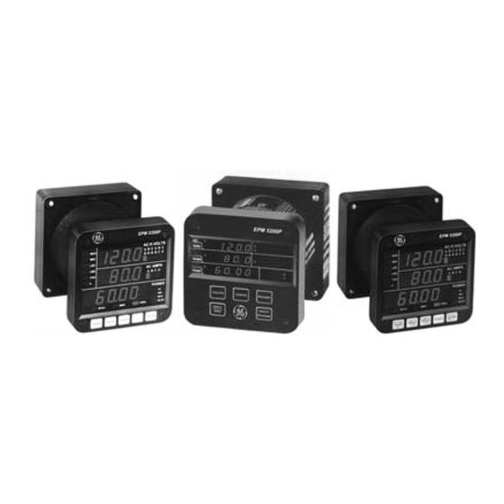
EPM 5200, 5300, 5350
DIGITAL MULTIFUNCTION POWER MONITORS
Instruction Manual
Copyright © 2004 GE Multilin
EUROPE
Avenida Pinoa 10 – 48710, Zamudio (Vizcaya) Spain
Tel: +34 94 485 88 00 Fax: +34 94 485 88 45
GEK-106557A
Advertisement
Table of Contents

Subscribe to Our Youtube Channel
Related Manuals for GE EPM 5300


Summary of Contents for GE EPM 5300
-
Page 1: Instruction Manual
E-mail: info.pm@indsys.ge.com Internet: http://www.GEindustrial.com/multilin EPM 5200, 5300, 5350 DIGITAL MULTIFUNCTION POWER MONITORS Instruction Manual GEK-106557A Copyright © 2004 GE Multilin EUROPE Avenida Pinoa 10 – 48710, Zamudio (Vizcaya) Spain Tel: +34 94 485 88 00 Fax: +34 94 485 88 45... -
Page 3: Table Of Contents
5.4: Viewing Individual Phase Indication for Power Functions ...25 5.5: Accessing Max/Min Values...26 5.6: Resetting Values...26 5.7: Resetting Hour Readings...28 GE Multilin 5.8: Accessing the LM1/LM2 ...1 5.9: Voltage Phase Reversal and 5.10: Access Modes ... 30 5:11: Print Operating Data... 30 5.12: Print Programming Data ... - Page 4 Imbalance ...75 13.2: Trip Relay...75 13.3: Group 7, Function 0—Voltage Phase Reversal Detection ...76 13.4: Group 7, Function 1— Percentage Voltage Phase Imbalance ...77 GE Multilin ROUP HAPTER ...55 HAPTER 15.1: Entering the Programming 15.2: Data Entry Sequence ... 81 15.3: Programming Groups ...
-
Page 5: Chapter 1: Ac Power Measurement
Apparent power (VA): The total power delivered to the load, and the vector sum of real power and reactive power. Power Factor (PF): The ratio between real power and apparent power: GE Multilin Line Single Phase 2 Wires... -
Page 6: Three-Phase System
In a three-phase system, the voltage levels between the phases and the neutral are uniform and defined Figure 1.3: Three-Phase System: (1) Delta, (2) Wye Apparent Power (VA) Real Power (W) and reactive power 1) Delta 2) Wye EPM 5000 series Advanced Power Meters Reactive Power (VAR) GE Multilin... -
Page 7: Consumption, Demand And Poor Power Factor
POOR POWER FACTOR: Results in reactive power consumption. Transferring reactive power over a distribution network causes energy loss. To force consumers to correct their Power Factor, utilities monitor reactive power consumption and penalize the user for Poor Power Factor. GE Multilin P = E P = E... -
Page 8: Waveform And Harmonics
The Futura+ monitors the harmonic distortion to the 31st harmonic. A waveform capture of distorted waveform is also available. % THD GRAPH EPM 5000 series Advanced Power Meters GE Multilin... -
Page 9: Chapter 2: Mechanical Installation
FREQ KVAR PHASE MAX/MIN VOLTS AMPS POWER LIMITS NEXT 4.375 Diagram 2.2: Installation with K-110 option for limited space conditions GE Multilin 4.50 AC VO LTS AC AM PS PO W ER KVAR KW H FREQ PHASE VOLTS AM PS... - Page 10 CONNECTOR TOGETHER. 0.80 CUTOUT 0.198 DIA. 4.0 DIA. 3.375 1.6875 3.375 Diagram 2.3: Standard cutout W Port EPM 5000 series Advanced Power Meters (2) 8-32 SCREWS WILL LINE UP WITH 2 PEMS ON THE BACK PLATE. BACK VIEW GE Multilin...
-
Page 11: Chapter 3: Electrical Installation
WATTS. Then press the Phase/Next button to cycle through the phases. After connecting the polarity of the CTs, the WATT and VAR readings should be correct. GE Industrial Systems CHAPTER 3: ELECTRICAL INSTALLATION Maximum Distance (CT to Meter) 120 F Table 3.1: CT Size and Maximum Distance... -
Page 12: Voltage Circuit
Connect local ground to terminal 3. This protects the unit from spikes and transients. EVERSAL USING VOLTAGE READINGS OPTION SUFFIX 115 A 230 A Table 3.2: Control Power and Current EPM 5000 series Advanced Power Meters CURRENT 0.1 AAC 0.05 AAC 0.10 ADC 0.25-0.5 ADC 0.10 AAC or DC GE Multilin... - Page 13 LINE LOAD I. Three Phase, Three-Wire System Delta with Direct Voltage and CTs Note: Remember to make sure Open Delta bit is programmed in the meters (See Chapter 9). GE Multilin CONTROL POWER EPM 5000 series Advanced Power Meters BACK VIEW...
- Page 14 Note: Remember to make sure Open Delta bit is programmed in the meter (see Chapter 9). BACK VIEW 10 11 PORT POWER BACK VIEW 10 11 PORT POWER EPM 5000 series Advanced Power Meters 12 13 12 13 GE Multilin...
- Page 15 LINE LOAD IV. Three-Phase Four-Wire Wye with Direct Voltage and CTs LINE LOAD V. Three Phase Four-Wire Wye with CT and PTs GE Multilin CONTROL POWER POWER EPM 5000 series Advanced Power Meters BACK VIEW 11 12 PORT BACK VIEW...
- Page 16 Program 1 for Single Phase or 2 for Dual Phase in GROUP 0, FUNCTION 7 to remove Three-Phase indicators from view. LINE LOAD VI. Single Phase with CT and PT Connection The EPM 5300P-S BACK VIEW PORT POWER EPM 5000 series Advanced Power Meters 12 13 10 11 GE Multilin...
- Page 17 LOAD LINE LOAD VIII. Three-Phase Four-Wire WYE with 2.5 Element Note: The 2.5 element option must be custom configured from the factory. You must pre-order this configuration. GE Multilin POWER VII. Dual-Phase with CTs and PTs BACK VIEW CONTROL POWER...
-
Page 18: Relay, Protection And Pulse Output
Relay turns off unless other conditions force it on. Relay connection (see Figure 3.1, below): Form C relays, rated 250V, 5A–2 each. KYZ relay output (Form C), rated 200V, 100mA–1 each. EPM 5300P RELAY OVERVIEW EPM 5000 series Advanced Power Meters GE Multilin... -
Page 19: Decimal Point Placement
Programming Mode GROUP 0, FUNCTION 6. The pulse value is dependent upon the Decimal Point Placement and is determined by the decimal increment of the power function assigned to the pulse. Refer to the situation that applies to the meter setting. GE Multilin N .O . N .C . - Page 20 0.001 Units W Hour P U L S E O U T P U T 2 P U L S E O U T P U T 1 P U L S E O U T P U T 0 GE Multilin...
-
Page 21: Rs-485
The unit operates up to 9600 baud. For a smaller number of instruments over a long distance, use a lower baud rate. Optimal recommended baud rate is 1200 baud, if noisy conditions exist. GE Multilin RS-232 COMMUNICATION CONNECTION CONNECTION FOR DB-9 FEMALE... - Page 22 RS-485 Hookup Diagram (2 wire) Half Duplex RS-485 Communications Port Model#SF485DB RS-485 UNICOM 2500 (Bottom View Shown) RS-232 Figure 4.2: 2-Wire RS-485 Communication Connection Installation half duplex 5300P Instruments (rear view) —Detail view on following page EPM 5000 series Advanced Power Meters GE Multilin...
-
Page 23: C Hapter 4: C Ommunication I Nstallation
RS-485 Hookup Diagram (2 wire) Half Duplex (Closed Loop) 5300P Instruments (rear view) RS-485 Communications Port Model #SF485DB UNICOM 2500 (Bottom View Shown) Figure 4.3: 2-Wire RS-485 Communication Connection Installation half duplex (closed loop) GE Multilin EPM 5000 series Advanced Power Meters... - Page 24 RS-485 Hookup Diagram (2 wire) Half Duplex: Detail View UNICOM 2500 (Bottom View Shown) Figure 4.4: 2-Wire RS-485 Communication Connection Installation half duplex, detail view RS-485 Communications Port Model# SF485DB R+ T+ EPM 5000 series Advanced Power Meters RS-485 Communications Port Model# SF485DB R+ T+ GE Multilin...
- Page 25 Connect the T+ wire of the Unicom 2500 to the R+ on the RS-485 port • Connect the R+ wire of the Unicom 2500 to the T+ on the RS-485 port GE Multilin 5300P Instruments (rear view) —Detail view on following page...
- Page 26 It shows the cross-over from R to T between the Unicom and the rest of the bus. Enlarged view of twisted pair segments EPM 5000 series Advanced Power Meters RS-485 Communications Port Model# SF485DB R+ T+ R- Receive Pair Transmit Pair GE Multilin...
-
Page 27: Network And Long Distance Communication
Use modems (dedicated or dial-up) when the instruments are located at great distances. However, set the modem to auto answer at the recommended value of 1200 baud rate, if noise conditions exist. Also, flow control must be disabled. GE Multilin DEVICE TRANSCEIVERS... -
Page 28: Rs-232C
RITE THE • Places new settings into nonvolatile memory; settings take effect after the modem powers up. RS485-RS232 C ANAGER ONVERTER ODES ETTINGS TO CTIVATE ROFILE INGS ESULT ODES ETTINGS TO CTIVATE ROFILE EPM 5000 series Advanced Power Meters GE Multilin... - Page 29 Is the Meter Address set correctly (see Part II: Programming Section)? • Is the correct protocol set? Modbus, DNP 3.0? • Set the meter for the appropriate protocol for the internal software. GE Multilin EPM 5000 series Advanced Power Meters...
- Page 30 CHAPTER 4: COMMUNICATION INSTALLATION EPM 5000 series Advanced Power Meters GE Multilin...
-
Page 31: Chapter 5: Overview
5300P. The key strokes for each model are identical. OLTS PRESS MAX/MIN/LIMITS TO ACCESS MAX, MIN, LM1 OR LM2 VALUES. Figure 5.1: The EPM 5300P front panel with display and keypad GE Industrial Systems OWER ± KW ± KVAR ± PF ± T... -
Page 32: Accessing The Power Functions
Press PHASE/NEXT for the desired phase. EPM 5000 series Advanced Power Meters AC VOLTS AC AMPS POWER KVAH FREQ KVAR MAX/MIN PHASE POWER VOLTS AMPS LIMITS NEXT AC VOLTS AC AMPS POWER FREQ KVAR KVAH PHASE MAX/MIN VOLTS AMPS POWER LIMITS NEXT harmonic GE Multilin... -
Page 33: Viewing Individual Phase Indication For Power Functions
PHASE POWER LIMITS Step 1: a. Press POWER to select power readings. Press PHASE/NEXT to select a specific power function (PF, KW, KVAR, KVA). GE Multilin POWER KVAR PHASE NEXT ! The display blanks and indicates the %THD value momentarily. -
Page 34: Accessing Max/Min Values
AC VOLTS AC AMPS POWER KVAH FREQ KVAR MAX/MIN PHASE POWER VOLTS AMPS LIMITS NEXT Step 3: a. Press MAX/MIN/LIMITS once to view the maximum reading for Volts C-N. ! The display blanks and momentarily indicates the max value. GE Multilin... - Page 35 !The display blanks, three dashes appear in middle display and digits begin scrolling in upper display. ! The password is 005. GE Multilin UNPROTECTED RESET AC VOLTS AC AMPS POWER KVAH FREQ KVAR MAX/MIN PHASE POWER...
-
Page 36: Resetting Hour Readings
EPM 5000 series Advanced Power Meters AC VOLTS AC VOLTS AC AMPS AC AMPS POWER POWER FREQ KVAR KVAH FREQ PHASE PHASE MAX/MIN POWER VOLTS AMPS POWER NEXT LIMITS NEXT ! Checkmarks appear, indicating a successful reset. GE Multilin KVAR... -
Page 37: Voltage Phase Reversal And Imbalance
Note: In the event Voltage Phase Reversal and Voltage Phase Imbalance occur simultaneously, the display alternates between the incorrect phase sequence and the exceeded limit percentage. After six seconds the display returns to the normal operating mode. GE Multilin a. To access the set limit, press MAX/MIN/LIMITS •... -
Page 38: Access Modes
Press AMPS until a 1 appears.. b. Press PHASE/ NEXT to select. EPM 5000 series Advanced Power Meters AC VOLTS AC AMPS POWER FREQ KVAR KVAH MAX/MIN PHASE POWER VOLTS AMPS LIMITS NEXT ! 111 appears, confirming a successful print command. GE Multilin... -
Page 39: Print Programming Data
MAX/MIN VOLTS AMPS POWER LIMITS Step 1: a. Press and hold PHASE/NEXT. b. Press AMPS until a 0 appears in the middle display. c. Release both buttons GE Multilin AC VOLTS AC AMPS POWER KVAH FREQ KVAR MAX/MIN PHASE POWER... - Page 40 Follow Steps 1 and 2, then press MAX/MIN/LIMITS for the firmware versions. Firmware versions: • Upper display—analog processor version • Middle display—digital processor EPM 5000 series Advanced Power Meters AC VOLTS AC AMPS POWER FREQ KVAR KVAH PHASE MAX/MIN POWER VOLTS AMPS LIMITS NEXT GE Multilin...
-
Page 41: Programming Overview
V O L T S A M P S L IM IT S N E X T S W IT C H E S : GE Industrial Systems CHAPTER 6: PROGRAMMAING OVERVIEW GROUPS, Functions, and Switch PACKS • GROUPS are the main category. -
Page 42: Data Entry
FUNCTION and GROUP level. Scrolls PACKS, digit counters and changes switch PACK position UP or DOWN. Activates new data entry and enters or exits from GROUP or FUNCTION level. EPM 5000 series Advanced Power Meters SED FOR ASSWORD NTRY GE Multilin... -
Page 43: Chapter 7: Epm 5200P
5. The annunciators are highlighted one at a time. NOTE: The Ethernet model, EPM 5350P, is covered in detail in Chapter 16 of this manual. See p. 40 for a comparison of the three models covered in this manual. GE Industrial Systems Volts Power... - Page 44 Pulse Outputs Digital Communication Modbus RTU Modbus ASCII DNP Protocol Modbus Plus Capability Analog Outputs Modbus TCP Ethernet 5300P 5200P 0.2% 0.3% 0.2% 0.3% 0.4% 0.6% 5300P 5200P EPM 5000 series Advanced Power Meters 5350P 0.2% 0.2% 0.4% 5350P GE Multilin...
-
Page 45: Chapter 8: Entering The Programming Mode
! If 3 is not already displayed: c. Press AMPS until 3 appears. d. Press PHASE/NEXT to multiply the 3 to 333. 333 flashes momentarily in middle display. GE Industrial Systems CHAPTER 8: ENTERING PROGRAMMING MODE Entering Programming Mode: AC VOLTS AC AMPS POWER... - Page 46 NOTE: AUTO SCROLLING will automatically show all of the readings on the face of the meter except LIMITS. To enter Auto Scrolling mode, follow the above steps except use the numbers 666 as the password. To exit Auto Scrolling mode, use the same procedure as described above. EPM 5000 series Advanced Power Meters GE Multilin...
-
Page 47: P Rogramming G Roup
Enter Group Level of Programming Mode (see Chp. 8). b. Press MAX/MIN/LIMITS until 0. appears in upper display. c. Press AMPS to activate the Group. GE Industrial Systems Function Integration Interval Meter Address for Communication Baud Rate for Communication... -
Page 48: Group 0, Function 1-The Meter Address
! Lower display indicates the current Meter Address. EPM 5000 series Advanced Power Meters AC VOLTS AC AMPS POWER KVAH FREQ KVAR MAX/MIN PHASE VOLTS AMPS POWER LIMITS NEXT AC VOLTS AC AMPS POWER KVAH FREQ KVAR MAX/MIN PHASE VOLTS AMPS POWER LIMITS NEXT GE Multilin... -
Page 49: Group 0, Function 2-Baud Rate
Step 1: a. Enter Group Level of Programming Mode (see Chp. 8). b. Press MAX/MIN/LIMITS until 0. appears. c. Press AMPS to activate the Group. GE Multilin POWER KVAR PHASE NEXT ! Repeat this procedure until new Address is entered. -
Page 50: Group 0, Function 3-System Configuration
VO LT AM P PO W ER LIM IT NEXT SW ITCHES: EPM 5000 series Advanced Power Meters AC VOLTS AC AMPS POWER KVAH FREQ KVAR MAX/MIN PHASE VOLTS AMPS POWER LIMITS NEXT PREVIO US SETTING SETTING KVAR GE Multilin... - Page 51 (To operate DC Output, disable PACK 3, Switch C) Print Operating and Programming Data (To print, set PACK 3 Switches C and D to UP Table 9-2: System Configuration—Switch Packs for Group 0, Function 3 GE Multilin FEATURE Reserved Reserved...
-
Page 52: Group 0, Function
RS232 port (i.e., when RS485 or DC outputs are being used). PRINTING OPTION 1. Printing through the keypad. 2. Corrupting data at a computer terminal while multiple meters poll. 3. Corrupting printing commands through communications. EPM 5000 series Advanced Power Meters GE Multilin... -
Page 53: Group 0, Function 3-Programming Procedure
! The previous Switch settings shift to middle display and four dashes appear in lower display. c. Press VOLTS to toggle the segments up or down for desired setting. d. Press AMPS to store each setting. GE Multilin POWER KVAR PHASE NEXT Step 2: a. -
Page 54: Relay Mode
R E S E T N O P O W E R T O T H E U N I T EPM 5000 series Advanced Power Meters Segment Position UP!Enable DOWN!Disable UP!AND DOWN!OR see Table 8-4 R E S E T GE Multilin... -
Page 55: Programming Steps
2. Enter in GROUP 4, FUNCTION 2, LIMIT 1, Segments: B, C, and D: UP, UP, DOWN. Value: 5.00 3. Enter in GROUP 4, FUNCTION 2, LIMIT 2, Segments: DOWN, UP, DOWN. Value: 4.00 GROUP 0—FUNCTION NUMBER 04.P 05.P GE Multilin PROGRAMMING STEPS: S E T R E S E T S E T... - Page 56 See Chapter 14 to Exit. EPM 5000 series Advanced Power Meters AC VOLTS AC AMPS POWER KVAH FREQ KVAR MAX/MIN PHASE VOLTS AMPS POWER LIMITS NEXT AC VOLTS AC AMPS POWER KVAH FREQ KVAR PHASE MAX/MIN VOLTS AMPS POWER LIMITS NEXT GE Multilin...
-
Page 57: Group 0, Functions 4-5-Time Delay For Relays 1 And 2 (Option - Nl)
(Procedures for both relays are the same). GROUP AND FUNCTION NUMBER 04.0 04.1 05.0 05.1 GE Multilin DESCRIPTION Relay 1: On to Off Delay Time Relay 1: Off to On Delay Time Relay 2: On to Off Delay Time Relay 2: Off to On Delay Time... - Page 58 See Chapter 14 to Exit. EPM 5000 series Advanced Power Meters AC VOLTS AC AMPS POWER KVAH FREQ KVAR PHASE MAX/MIN VOLTS AMPS POWER LIMITS NEXT AC VOLTS AC AMPS POWER KVAH FREQ KVAR PHASE MAX/MIN VOLTS AMPS POWER LIMITS NEXT GE Multilin...
-
Page 59: Group 0, Function 6-Kyz Parameter Selection
Enter Group Level of Programming Mode (see Chp. 8). b. Press MAX/MIN/LIMITS until 0. appears in upper display. c. Press AMPS to activate the Group. GE Multilin DESCRIPTION Disable KYZ Positive Watt Hour KYZ VA Hour KYZ Negative Watt Hour KYZ... - Page 60 PTION ONLY KYZ PULSE KYZ PULSE VALUE VALUE PER PER WATT HOUR FSW=9.999 FSW=99.99 0.001 unit WH 0.0005 unit WH 0.0001 unit WH 0.00005 unit WH 0.001 unit WH 0.002 unit WH 0.01 unit WH 0.02 unit WH GE Multilin...
- Page 61 Enter Group Level of Programming Mode, (see Chp. 8). b. Press MAX/MIN/LIMITS until 0. appears in upper display. c. Press AMPS to activate the Group. GE Multilin 2: FSW=999.9 ITUATION • Selection is Multiply by 2 • This means that every .05 unit WH=1 pulse.
-
Page 62: Group 0, Function 7-Number Of Phases
EPM 5000 series Advanced Power Meters AC VOLTS AC AMPS POWER KVAH FREQ KVAR MAX/MIN PHASE VOLTS AMPS POWER LIMITS NEXT Step 3: a. Press VOLTS to select numbers 1, 2 or 3. b. Press AMPS to store. See Chapter 14 to Exit. GE Multilin... -
Page 63: Chapter 10: Programming Group 1
10.1: Group 1, Function 0—Full Scale Voltage Settings, Scale & Decimal Point Placement GROUP AND FUNCTION NUMBER NOTE: Tables 10-2 and 10-3 contain Full Scale Settings for typical voltages and currents (PT and CT arrangements). GE Multilin FORMULAS: Primary Secondary Full Scale Selection for Volts... - Page 64 ! Lower display indicates Full Scale for voltage. EPM 5000 series Advanced Power Meters FULL SCALE 9.00 KV 120.0 0480 V 014.4 KV 0300 V 072.0 KV 138.0 KV AC VOLTS AC AMPS POWER KVAH FREQ KVAR MAX/MIN PHASE VOLTS AMPS POWER LIMITS NEXT GE Multilin...
- Page 65 ! Middle display indicates present Full Scale for volts. ! Four dashes appear in lower display. ! Enter the four digit full scale. a. Press VOLTS to increase the digit number. b. Press AMPS to store each digit. GE Multilin POWER KVAR PHASE NEXT...
-
Page 66: Group 1, Function 1-Amperage Full Scale
Press MAX/MIN/LIMITS until 11. appears in upper display. ! Middle display indicates Scale Factor Setting. ! Lower display indicates Full Scale. EPM 5000 series Advanced Power Meters AC VOLTS AC AMPS POWER KVAH FREQ KVAR MAX/MIN PHASE POWER VOLTS AMPS LIMITS NEXT GE Multilin... -
Page 67: Group 1, Function 2-Scale Selection And Decimal Placement For Watts
FUNCTION 2. NOTE: Shift the decimal left to increase resolution. Wattage should not exceed a numeral value of 2500. Shift the decimal one position right to decrease resolution. GE Multilin KVAR NEXT... - Page 68 NOTE: In some applications where the load is normally very low, the watts resolution can be increased by moving the decimal point one position left. ⋅ 3 = 1,440,000 W EPM 5000 series Advanced Power Meters GE Multilin...
- Page 69 ! Lower display is replaced with a single dash. b. Press VOLTS to move the segment ! UP signifies - megawatts. ! DOWN signifies - kilowatts.. c. Press AMPS to store. GE Multilin KVAR NEXT Step 2: a. Press AMPS to activate the Group.
- Page 70 CHAPTER 10: PROGRAMMING GROUP 1 EPM 5000 series Advanced Power Meters GE Multilin...
-
Page 71: Chapter 11: Programming Group 2: Meter Calibration
GROUP 1, for better accuracy than the specification. However, if a full scale is ever changed to a higher value than the calibrated value, the value may be less accurate. GE Industrial Systems FUNCTION High End Calibration—Volts AN, BN, CN High End Calibration—Amps A, B, C... -
Page 72: Group 2, Functions
A and then moves to B and C. a. Press MAX/MIN/LIMITS to change Function number. EPM 5000 series Advanced Power Meters GROUP 2 VALUE 1440 1440 0300 2000 1000 AC VOLTS AC AMPS POWER KVAH FREQ KVAR MAX/MIN PHASE POWER VOLTS AMPS LIMITS NEXT GE Multilin... - Page 73 Press MAX/MIN/LIMITS until 2. appears in upper display. c. Press AMPS to activate the Group. ! A one digit password is required to continue. d. Press VOLTS until 5 appears. e. Press AMPS to select. GE Multilin POWER KVAR PHASE NEXT Step 4: a.
- Page 74 Press VOLTS to select digits. b. Press AMPS to store and proceed to B or C within the group. c. Press MAX/MIN/LIMITS to end calibration procedure. See Chapter 14 to Exit. KVAR NEXT EPM 5000 series Advanced Power Meters GE Multilin...
-
Page 75: Limit And Relay
1) Volts phase-to-neutral 2) Volts phase-to-phase 3) Amps A, B, C 4) Amps neutral GE Industrial Systems LM1 AND LM2 SET LIMITS LM1 is triggered LM2 is triggered PHASES 5300P Advanced Power Meter... -
Page 76: Group 4, Functions 0-3-Lm1/Lm2 Set Limits
A B O V E / B E L O W , T R I P R E L A Y 1 A N D T R I P R E L A Y 2 . FUNCTION RELAY 2 VALUE Digit Up-enabled 0-9999 Digit Down- 0-9999 disabled Digit Up-enabled 0-9999 Digit Down- 0-9999 disabled GE Multilin... -
Page 77: Group 5, Functions 0-7-Lm1/Lm2 Set Limits
Kilowatt, Kilovar, Kilovolt-ampere, Power Factor, Frequency, negative Kilovar, negative Power Factor, and negative Kilowatt. GROUP AND FUNCTION NUMBER Table 12.4: Group 5 Programming Format for Limit Condition GE Multilin ABOVE/BELOW RELAY 1 Digit Up Digit Up... -
Page 78: Special Cases
Table 12.6: Group 5: Example for Function 0 EPM 5000 series Advanced Power Meters SWITCH 3 VALUE RELAY 2 Digit Up-enabled 0-9999 Digit Down- 0-9999 disabled Digit Up-enabled 0-9999 Digit Down- 0-9999 disabled SWITCH 3 VALUE Digit Down 0120 Digit Up 0090 GE Multilin... - Page 79 Digit Up-trigger above level Digit Down-trigger below level GE Multilin A C V O L T S A C A M P S F R O M L E F T T O R I G H T : S E T L I M I T A B O V E / B E L O W , T R I P R E L A Y 1 A N D T R I P R E L A Y 2 .
-
Page 80: Group 6, Functions 0-5-Lm1/Lm2 Set Limits And Relay Triggers For Over/Under %Thd Conditions
! The LM1 or LM2 annunciator indicates the limit being displayed. EPM 5000 series Advanced Power Meters SWITCH 3 LEVEL RELAY 2 Digit Down 012.0 Digit Up 009.0 AC VOLTS FUNCTION AC AMPS RELAY SWITCHES POWER FREQ KVAR KVAH PHASE MAX/MIN POWER VOLTS AMPS LIMITS NEXT GE Multilin... - Page 81 ! The Set Above/Below will be set to below. ! Trip Relay 1 will be disabled. ! Trip Relay 2 will be disabled. ! The Setup Level will be set to 0000. GE Multilin POWER KVAR PHASE NEXT...
- Page 82 Press MAX/MIN/LIMITS TO PROGRAM ANOTHER Function (refer to Step 2). See Chapter 14 to Exit. EPM 5000 series Advanced Power Meters AC VOLTS AC AMPS POWER KVAH FREQ KVAR MAX/MIN PHASE POWER VOLTS AMPS LIMITS NEXT GE Multilin...
-
Page 83: Chapter 13: Phase Reversal
&LEVEL The level at which the warning mechanism trips percentage of voltage imbalance. 'ENABLE/DISABLE In the event of Phase Reversal, whether to enable or disable Phase Reversal Detection. GE Industrial Systems Limits Triggered Limits Not Triggered 10:00 AM 11:00 AM... -
Page 84: Chapter 14: Exiting Programming Mode
Press AMPS to store. EPM 5000 series Advanced Power Meters AC VOLTS AC AMPS POWER KVAH FREQ KVAR PHASE MAX/MIN VOLTS AMPS POWER LIMITS NEXT AC VOLTS AC AMPS POWER KVAR KVAH FREQ MAX/MIN PHASE POWER VOLTS AMPS LIMITS NEXT GE Multilin... -
Page 85: Group 7, Function 1-Percentage Voltage Phase Imbalance
Enter Group Level of Programming Mode (see Chp. 9). b. Press MAX/MIN/LIMITS until 7. appears in upper display. c. Press AMPS to activate the Group. GE Multilin KVAR KVAR Step 2: a. Press MAX/MIN/LIMITS until 71. appears in upper display. - Page 86 ! Four dashes appear in lower display. a. Press VOLTS to scroll through digits. b. Press AMPS to select desired digit. KVAR EPM 5000 series Advanced Power Meters AC VOLTS AC AMPS POWER KVAH FREQ KVAR MAX/MIN PHASE VOLTS POWER AMPS LIMITS NEXT GE Multilin...
-
Page 87: E Xiting The P Rogramming M Ode
Press MAX/MIN/LIMITS until E. appears in upper display (for Exit). b. Press AMPS to exit entirely from Programming Mode. GE Industrial Systems CHAPTER 14: EXITING PROGRAMMING MODE KVAR Step 1a.: a. Press AMPS to exit from Function Level to Group Level. - Page 88 CHAPTER 14: EXITING PROGRAMMING MODE EPM 5000 series Advanced Power Meters GE Multilin...
-
Page 89: Chapter 15: Programming Quick Reference
Full Scale Settings. Voltage Full Scale, Current Full Scale and Power Function Full Scale. Meter Calibration Calibration Ratios Volts and Current Limits Power Function Limits THD Limits Imbalance Reversal Limits DC Output Calibration GE Industrial Systems CHAPTER 15: PROGRAMMING QUICK REFERENCE Description 5300P Advanced Power Meter... - Page 90 041. OFF to ON delay time 05. Relay 2 Programming 05P. A. Imb/Rev Selection B. Reserved C. & D. Relay Mode Selection 050. ON to OFF delay time 051. OFF to ON delay time EPM 5000 series Advanced Power Meters GE Multilin...
-
Page 91: Group 1: Full Scale Setup
15.8: Group 4: Volt/Current Limits 40. Volt AN, Volt BN, and Volt CN Limits. 41. Volt AB, Volt BC, and Volt CA Limits. 42. Amp A, Amp B, and Amp C Limits. 43. Amp N Limits. GE Multilin EPM 5000 series Advanced Power Meters... -
Page 92: Group 5: Power Function Limits
A. 75 Volts Suffix Selection B. 300 Volts Suffix Selection C. Frequency D. 10 Channel Selection 8P1. Power Uni/Bi Directional Selection A. Port 0 B. Port 1 C. Port 2 D. Port 3 EPM 5000 series Advanced Power Meters GE Multilin... - Page 93 81F. Parameter Mapping 81L. Low-End Calibration 81H. High-End Calibration 89. DC output Port 9 89F. Parameter Mapping 89L. Low-End Calibration 89H. High-End Calibration GE Multilin KEY DESIGNATIONS MAX/MIN/LIMITS VOLTS AMPS EPM 5000 series Advanced Power Meters Scroll Groups Scroll Functions ...
- Page 94 CHAPTER 15: PROGRAMMING QUICK REFERENCE EPM 5000 series Advanced Power Meters GE Multilin...
-
Page 95: Chapter 16: Ethernet Option
The Ethernet connection is made with a small module added to the back of the meter. This small but powerful module has simply an RJ-45 Port and four Status LEDs. ETHERNET 10 BASE T RJ-45 LED DETAIL MOD.# GREEN 1 4 GREEN SER.# RED 3 2 YELLOW GE Multilin EPM 5000 series Advanced Power Meters... -
Page 96: Ethernet Option Setup
2x: RAM error 3x: Network controller error 4x: EEPROM checksum error 5x: Duplicated IP address on network* 6x: Software does not match hardware* 4x: Faulty network connection* 5x: No DCHP response received* EPM 5000 series Advanced Power Meters GE Multilin... -
Page 97: Default Ip Address
On a Unix host, create an entry in the host’s ARP table using the intended IP address and the hardware address of the Ethernet Interface, which is found on the product label. arp –s 191.12.3.77 00:20:4a:xx:xx:xx GE Multilin EPM 5000 series Advanced Power Meters... -
Page 98: Network Configuration
9999. From the Windows Start menu, click Run and type the following command, where x.x.x.x is the IP address and 9999 is the Ethernet Interface’s fixed network configuration port number. telnet x.x.x.x 9999 NOTE: Be sure to include a space between the IP address and 9999. EPM 5000 series Advanced Power Meters GE Multilin... -
Page 99: Configuration Parameters
Valid baud rates are 1200, 2400, 4800 and 9600 (default). For the EPM 5350P, default settings are 9600 baud rate, 8 data, 1 stop, no parity, Modbus RTU. GE Multilin - 0.0.0.0/DHCP (Customer Configurable) --- not set ---... - Page 100 GE Multilin 215 Anderson Avenue Markham, Ontario Canada L6E 1B3 Tel: (905) 294-6222 Fax: (905) 201-2098 http://www.GEindustrial.com/multilin...
Need help?
Do you have a question about the EPM 5300 and is the answer not in the manual?
Questions and answers